EP0906825B1 - Procédé d'opération d'une presse rotative - Google Patents
Procédé d'opération d'une presse rotative Download PDFInfo
- Publication number
- EP0906825B1 EP0906825B1 EP98115978A EP98115978A EP0906825B1 EP 0906825 B1 EP0906825 B1 EP 0906825B1 EP 98115978 A EP98115978 A EP 98115978A EP 98115978 A EP98115978 A EP 98115978A EP 0906825 B1 EP0906825 B1 EP 0906825B1
- Authority
- EP
- European Patent Office
- Prior art keywords
- printing
- image
- imaging
- printing form
- Prior art date
- Legal status (The legal status is an assumption and is not a legal conclusion. Google has not performed a legal analysis and makes no representation as to the accuracy of the status listed.)
- Expired - Lifetime
Links
- 238000000034 method Methods 0.000 title claims description 39
- 238000007639 printing Methods 0.000 claims description 317
- 238000004140 cleaning Methods 0.000 claims description 22
- 230000008859 change Effects 0.000 claims description 10
- 238000003384 imaging method Methods 0.000 description 78
- 230000008569 process Effects 0.000 description 8
- 230000008878 coupling Effects 0.000 description 5
- 238000010168 coupling process Methods 0.000 description 5
- 238000005859 coupling reaction Methods 0.000 description 5
- 239000002699 waste material Substances 0.000 description 4
- 238000004519 manufacturing process Methods 0.000 description 3
- 239000000463 material Substances 0.000 description 3
- 238000007645 offset printing Methods 0.000 description 3
- 239000000126 substance Substances 0.000 description 3
- 239000000758 substrate Substances 0.000 description 3
- 238000011144 upstream manufacturing Methods 0.000 description 3
- 230000004913 activation Effects 0.000 description 2
- 230000005540 biological transmission Effects 0.000 description 2
- 239000003086 colorant Substances 0.000 description 2
- 238000013500 data storage Methods 0.000 description 2
- 239000012530 fluid Substances 0.000 description 2
- 239000011888 foil Substances 0.000 description 2
- 230000007935 neutral effect Effects 0.000 description 2
- 238000003825 pressing Methods 0.000 description 2
- 230000005855 radiation Effects 0.000 description 2
- 230000001360 synchronised effect Effects 0.000 description 2
- 238000010521 absorption reaction Methods 0.000 description 1
- 230000003796 beauty Effects 0.000 description 1
- 238000010276 construction Methods 0.000 description 1
- 230000009849 deactivation Effects 0.000 description 1
- 238000006073 displacement reaction Methods 0.000 description 1
- 239000004744 fabric Substances 0.000 description 1
- 239000000835 fiber Substances 0.000 description 1
- 230000010354 integration Effects 0.000 description 1
- 230000003993 interaction Effects 0.000 description 1
- 239000000155 melt Substances 0.000 description 1
- 229920001296 polysiloxane Polymers 0.000 description 1
- 238000000926 separation method Methods 0.000 description 1
- 238000003860 storage Methods 0.000 description 1
- 238000005406 washing Methods 0.000 description 1
- 238000004804 winding Methods 0.000 description 1
Images

Classifications
-
- B—PERFORMING OPERATIONS; TRANSPORTING
- B41—PRINTING; LINING MACHINES; TYPEWRITERS; STAMPS
- B41F—PRINTING MACHINES OR PRESSES
- B41F7/00—Rotary lithographic machines
- B41F7/02—Rotary lithographic machines for offset printing
-
- B—PERFORMING OPERATIONS; TRANSPORTING
- B41—PRINTING; LINING MACHINES; TYPEWRITERS; STAMPS
- B41P—INDEXING SCHEME RELATING TO PRINTING, LINING MACHINES, TYPEWRITERS, AND TO STAMPS
- B41P2217/00—Printing machines of special types or for particular purposes
- B41P2217/10—Printing machines of special types or for particular purposes characterised by their constructional features
- B41P2217/13—Machines with double or multiple printing units for "flying" printing plates exchange
-
- B—PERFORMING OPERATIONS; TRANSPORTING
- B41—PRINTING; LINING MACHINES; TYPEWRITERS; STAMPS
- B41P—INDEXING SCHEME RELATING TO PRINTING, LINING MACHINES, TYPEWRITERS, AND TO STAMPS
- B41P2227/00—Mounting or handling printing plates; Forming printing surfaces in situ
- B41P2227/70—Forming the printing surface directly on the form cylinder
Definitions
- DE-PS 28 44 418 is a web-fed rotary printing press with flying Print image change described in an impression unit, that is, when reaching a certain edition with a first impression of the printing unit currently printing turned off and another printing unit of the impression unit without machine downtime in Is put into operation. While the other printing unit is working, the one that is turned off can be switched off Printing unit to be prepared for the next impression.
- An illustration of printing forms in the printing press is not provided here, so that for small print runs per Print image the cost of prepress, e.g. B. the photochemical plate copy, a represent a comparatively large proportion of the total costs. Automation of the Printing plate changes can only be achieved with considerable technical effort.
- EP 0 368 179 A2 describes a pixel transmission device which first with means of electrography, electrophotography or magnetography Charge image generated on a transfer belt on which a subsequently applied toner-like substance adheres more or less depending on the charge.
- the transfer belt is then heated by means of a heatable unit which functions as an image delivery unit
- the roller is pressed against a printing form cylinder so that it melts again Substance is transferred from the transfer belt to the printing form cylinder.
- the Printing form cylinder is already illustrated, the transfer belt from the printing form cylinder switched off. While production continues on the printing cylinder just illustrated, may the transfer belt to be placed on another printing form cylinder and another in Form of substance parts temporarily stored print image can be transferred to the latter.
- the time of production can be used by means of the pixel transmission device to transfer a new print image onto the transfer belt.
- the methods for operating a Rotary printing press with at least two images that can be imaged in the printing press are, among other things, characterized in that during the printing with the first printing form second printing form is illustrated.
- the second printing form is illustrated in particular for printing with the first printing form after the printing second printing form.
- the methods can also be carried out by means of a device in which the first Printing form and the second printing form a single common imaging device is assigned, which can be used for imaging the first and the second printing form.
- the invention in contrast to the dynamic or erasable forms in as output devices for Personal computer used, e.g. B. printers working according to the electrographic principle and plotter, the invention relates to uniquely imageable - that is, the master system assignable - printing forms with a storable, non-erasable print image.
- This Printing forms can be in the form of a printing plate, a sleeve or a curable Fluid layer or preferably a print film that can be unwound and wound up Printing form cylinders to be applied.
- the printing forms can be used as offset printing forms, e.g. B. as conventional wet offset printing forms or as damp-proof working Dry offset printing forms, and also as printing forms for direct planographic printing (Dilitho) be trained.
- the printing form can be cleaned by means of a cleaning device or by the Substrate.
- the one to be printed on or off can be used an existing printing material used especially for cleaning become.
- Imaging residues can be removed from the substrate directly during the Start of printing z. B. by few sheets becoming waste, or in one Print preceding cleaning run to be included.
- the imaging process is one that follows the actual imaging process Cleaning process not necessary. Instead, other processes can Make the printing form ready for printing and attach the images.
- a total edition of a printed product can be made up of the first partial edition, which with a Print image or impression should be provided, and the second partial edition, which with to be provided with another printed image or impression image.
- the second printing form is imaged in the printing press, z. B. irradiated and cleaned.
- printing of the first partial edition is required far more time than the entire imaging process, so that this can be carried out completely during the printing of the first partial edition.
- Printing units can be the actual print image of the total print run of the order are printed, the first and second printing device additional impressions in this actual print image can be printed.
- the other printing units can be conventional Include printing forms, the z. B. by means of plate copying outside the printing press and cannot be imaged within the printing press.
- alternate images can be used and an alternate use of the first printing form and the second printing form respectively.
- the method can also be done using more are carried out as two printing forms that can be imaged in the printing press, where z. B. a first printing form is in use, while a second printing form and a third printing form can be illustrated.
- a first printing form is in use
- a second printing form and a third printing form can be illustrated.
- the first and the second Imaging device of the device for performing the method can by a separately assigned one or by a single selectable one common electronic control device can be controlled.
- a device can be used to carry out a special embodiment of the inventive method, which includes that in an already printed Print image can be printed in-line impressions, be trained.
- a Rotary printing machine can be designed such that in the substrate conveying direction seen the one or two-sided four or multi-color printing necessary printing units are subordinated to two impression devices.
- Each of the Impression devices can e.g. B. on and on an impression cylinder adjustable printing form cylinder or one on the impression cylinder on and adjustable printing form and blanket cylinder combination.
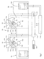
- the rotary printing machine shown in Fig. 1 in a row with A device for carrying out the method according to the invention comprises a first one Printing unit 82, a second printing unit 84, a sheet feeder 86, one Sheet transfer and / or sheet turning device 88, a sheet delivery 90 and a central control device 118 for controlling the said Components of the printing press including those not shown in FIG. 1 Drives of the components and of the printing units 82, 84, not shown assigned ink or ink and dampening units.
- Each of the printing units 82, 84 includes an impression cylinder 96, 102, a blanket cylinder 94, 100 and a printing form cylinder 92, 98 with a printing form 104, 110.
- the printing form 104, 110 are a cleaning device 108, 114 and one each Imaging device 106, 112 assigned.
- the imaging devices 106, 112 can be a laser, a modulator downstream of this and a die include modulated radiation to a focusing optics transmitting fiber optics.
- the Focusing optics can spiral over the surface of the printing form 104, 110 on the rotating printing form cylinders 92, 98 are guided, where the laser beam to the Positions of the grid drills the desired cells.
- the Imaging devices 106, 112 are by a Imaging control device 116 controlled, which is in a first operating mode the first imaging device 106 and in a second operating mode controls second imaging device 112 and that with the central Control device 118 is connected.
- the central control device 118 is connected to a control panel 138, via which in a known manner Operating parameters and commands for controlling the printing press can be entered.
- a control panel 138 Through which in a known manner Operating parameters and commands for controlling the printing press can be entered.
- Imaging control device 116 or an imaging control by the central control device 118 are also possible.
- the printing form cylinders 92, 98 are in an imaging position movable, in which they do not contact the blanket cylinders 94, 100.
- a Positioning 120, 124 of the imaging devices 106, 112 can additionally be provided so that in this way a suitable distance for imaging between the effective elements of the imaging devices 106, 112, e.g. B. Laser diodes or focusing optics, and the printing form surface of the Printing forms 104, 110 can be set and kept constant, so that a exactly defined diameter of the grid points or cells is guaranteed.
- the Cleaning devices 108, 114 are also positionable and can be in shape of a winding and unwinding cleaning cloth in combination with one the pressing element pressing the printing plate surface may be formed, wherein a cleaning fluid indirectly via the cleaning device or directly can be applied to the printing form surface.
- the implementation of the method according to the invention is exemplified below explained in the event that two print jobs are processed.
- the first Print job is already using the second printing unit 84 illustrated second printing form 110 printed.
- Sheets 128 are from Sheet feeder 86 to the first printing unit 82, from this via the Sheet transfer device 88 to the second printing unit 84 and via this to Supported sheet delivery 90.
- the first printing form 104 is imaged in the first Printing unit 82 for the second print job, which is the first print job to be processed below.
- the printing form cylinder 92 is switched off from the blanket cylinder 94, the Blanket cylinder 94 placed on the impression cylinder 96 or by this can be turned off.
- Processing the complete edition of the first Print job can be a sufficient for imaging the first printing form 104 Require a period of time so that complete imaging, including one Burning all pixels into the first printing form 104 and one subsequent cleaning of the first printing form 104 from the ablative Imaging of thermally decomposed printing plate material using the Cleaning device 108 can be carried out in this period.
- To Processing the first print job becomes processing the second Print job started by the printing form cylinder 92 in a working position is brought, in which an interaction with the blanket cylinder 94th is given and by simultaneously the printing form cylinder 98 from such Working position is brought into an imaging position.
- the imaging controller 116 can be operated manually or, as shown, by the central control device 118 optionally in a first operating mode - for Activation of the first imaging device 106 for imaging the first Printing form 104 - and in a second operating mode - for controlling the second Imaging device 112 for imaging the second printing form 110 - switchable his.
- the print image data and other data for imaging the printing forms 104, 110 can be from the imaging control device 116 in the data flow upstream electronic publishing systems on-line or, as shown, by portable data storage media 130, e.g. B. floppy disks.
- the Connection of the imaging control device 116 to the central one Control device 118 and also an integration in the latter enable a further one Use of the image data for the control of further machine components, e.g.
- the printing press 80 for printing unit-specific inking unit setting, as well as a current operating status the printing press 80, in particular the printing units 82, 84 Signal flow to the imaging control device 116. Furthermore, one is also optional Connection of the imaging control device 116 to the Imaging devices 106, 112 and their activation and deactivation possible by manual operation.
- the printing press 80 in other functions also as a multi-color printing machine and as a Schönund Back printing machine operated, z. B. one after the other imaging of the printing forms 104, 110 can take place before the start of printing.
- the printing press 80 can comprise further printing units, which are the printing units 82, 84 can be upstream, intermediate and downstream.
- the invention Procedure using appropriate control software in one Microprocessor circuit comprising central control device 118 realized.
- An example of a program flow chart for such control software is shown in Fig. 2 and is referred to below as an example to Fig. 1 described.
- step 142 After starting the program in stage 140, which, for. B. with turning on Printing machine can take place, in step 142, the printing positions in second printing unit 84 set, z. B. the one already fully illustrated first Printing form cylinder 98 carrying printing form 110 from an imaging position in a working position is brought relative to the blanket cylinder 100.
- the next program stage 144 is the printing in the second printing unit 84 Printing machine 80 started.
- the imaging of the first takes place in a subsequent program stage 146
- Printing form 104 which is complete in a further program stage 148 is completed, so that the first printing form 104 is now ready for printing.
- an adjustment of the printing positions in the first printing unit 82 e.g. B.
- the second printing form 110 is renewed, z. B. by manually replacing a printing form sleeve or a printing plate is automatically changed or a print film web that can be wound up and unwound is clocked further, so that the printing form cylinder 98 with a new imageable Printing form 110 is provided.
- a further program stage 156 there is a Return query, that is, whether the second print job has other print jobs follow or whether the number n of successive orders to be processed is greater than that Number z orders completed.
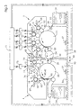
- the satellite printing unit 2 and the Imprinting unit 4 can be coupled to one another with the connecting element 78, wherein further couplings are not shown in the figure.
- the driving Coupling can e.g. B. via an electronic coupling of separate drives both Units 2, 4 by means of the central control device 71 or via one into a of units 2; 4 integrated central drive and one of its drive power for other unit 2; 4 transmitting gear, z. B. realized a gear train his.
- At least one of the units 2; 4 is displaceable in a direction 46, while the other unit 2; 4 can be anchored stationary in the foundation 33.
- the Displaceability of the units 2, 4 can be guided in rails 35 Rollers 36 or other guides facilitating displacements can be made possible, the displaceable units 2, 4 in the foundation 33 with locking elements 37 can be locked.
- the units 2, 4 and operation with additional modules e.g. B. bow-laying and -interpreting and print processing modules, - d. H. an operational one optional combination and also separate operation of units 2, 4 - possible.
- the satellite printing unit 2 can essentially with a similar or mirror image trained additional satellite printing unit be combined so that a two-sided four or multi-color printing or a single-sided eight or multi-color printing is possible.
- the method according to the invention can be within only one of the satellite printing units or impression units or be carried out across modules.
- the sheet transfer device 22, 24, 26 operates as one Turning device, wherein the transfer drum 24 as a storage drum with the second transfer drum 26 in which acts here as a turning drum cooperates in a known manner, acts so that the printing sheets 30 applied the impression unit 4 are transferred, the printing sheets 30 with their previous front 40 rest on the impression cylinder 20 and a Printing the back 44 is feasible.
- the arrowheads in Fig. 3 symbolize the colors printed on the printed sheet on the respective page.
- a first variant includes that an illustration of one or more impression devices 16, 18 of the unit 4 during printing with the printing devices 5, 7, 9, 11 of the unit 2 or that during printing with one or more of the Impression devices 16, 18 of unit 4 illustrate one or more Printing devices 5, 7, 9, 11 of the unit 2 takes place.
- This first variant is too applicable to two coupled satellite printing units.
- one or more of the printing forms 5, 7, 9, 11 during printing with one or more of the printing forms 5, 7, 9, 11 imaged can be used in separate operation of the Satellite printing unit 2 as well as with other modules, eg. B. the Impression unit 4, coupled operation can be realized.
- the preferred third variant includes the implementation of the invention Method by means of the devices 62 integrated in the impression unit 4, 70, 72, 73.
- the z. B. trained as a write head with laser diodes Imaging device 72 is in a first position a for imaging the first Printing form 49 and in a second position b for imaging the second Printing form 51 and optionally in a neutral position c. This can preferably done by pivoting the imaging device 72. In addition to the pivoting movement 74, a further one - if appropriate with this forcibly synchronized movement 76 of the imaging device 72 respectively.
- a single imaging device 66 with an associated one Imaging control device 73 for sequential imaging of the Printing devices 6, 8, 10, 12 or printing forms 5, 7, 9, 11 are used.
- Fig. 3 it is shown that the impression device 16 except for imaging Operation has taken place, for which the printing form cylinder 58 and the inking unit 60 Printing form cylinder 58 and the blanket cylinder 56 and the blanket cylinder 56 and impression cylinder 20 are separated and parked. While four-color printed images of a first printed in the satellite printing unit 2 Partial order on the front side 42 of the printing sheet with the second printing form 51 18 impression images are printed in the second impression device, one takes place Illustration of the first printing form 49 of the first impression device 16 for the Imprinting another imprint image into four-color print images of a second one Part order.
- Printing form 49 can illustrate the second printing form 51 for a third Partial order take place, the printing form 51 brought first by a new one imageable printing form is replaced, then irradiation with the Imaging device 62 and this one may be required Cleaning the printing form 51 can be done with the cleaning device 62.
Landscapes
- Engineering & Computer Science (AREA)
- Mechanical Engineering (AREA)
- Inking, Control Or Cleaning Of Printing Machines (AREA)
- Rotary Presses (AREA)
- Manufacture Or Reproduction Of Printing Formes (AREA)
Claims (8)
- Procédé destiné à faire fonctionner une machine à imprimer rotative ou rotative d'impression comprenant au moins deux plaques d'impression ou formes d'impression dont l'image peut être formée dans la machine à imprimer, et avec lesquelles il est possible d'effectuer plusieurs impressions après une formation d'image unique,
caractérisé en ce qu'avec les plaques d'impression (49, 51 ; 104, 110) sont imprimés un premier contrat d'impression et un second contrat d'impression,
l'image de la seconde plaque d'impression (51, 110) pour l'impression du second contrat d'impression étant formée durant l'impression du premier contrat d'impression avec la première plaque d'impression (49, 104),
cette formation de l'image sur la seconde plaque d'impression (51, 110) étant effectuée dans la machine à imprimer,
le changement des plaques d'impression (49, 51 ; 104, 110) étant effectué en marche entre l'utilisation de la première plaque d'impression (49, 104) destinée à imprimer le premier contrat d'impression, et l'utilisation de la seconde plaque d'impression (51, 110) destinée à imprimer le second contrat d'impression, et
la formation de l'image des plaques d'impression (49, 51 ; 104, 110) étant effectuée par une irradiation localisée. - Procédé destiné à faire fonctionner une machine à imprimer rotative ou rotative d'impression comprenant au moins deux plaques d'impression ou formes d'impression dont l'image peut être formée dans la machine à imprimer, et avec lesquelles il est possible d'effectuer plusieurs impressions après une formation d'image unique,
caractérisé en ce qu'avec les plaques d'impression (49, 51 ; 104, 110) est imprimée une édition globale constituée d'une première édition partielle et d'une seconde édition partielle,
l'image de la seconde plaque d'impression (51, 110) pour l'impression de la seconde édition partielle étant formée durant l'impression de la première édition partielle avec la première plaque d'impression (49, 104),
cette formation de l'image sur la seconde plaque d'impression (51, 110) étant effectuée dans la machine à imprimer,
le changement des plaques d'impression (49, 51 ; 104, 110) étant effectué en marche entre l'utilisation de la première plaque d'impression (49, 104) destinée à imprimer la première édition partielle, et l'utilisation de la seconde plaque d'impression (51, 110) destinés à imprimer la seconde édition partielle, et
la formation de l'image des plaques d'impression (49, 51 ; 104, 110) étant effectuée par une irradiation localisée. - Procédé selon la revendication 1 ou 2, caractérisé en ce que les plaques d'impression (49, 51 ; 104, 110), après irradiation, sont nettoyées de résidus de formation de l'image, par une opération de nettoyage.
- Procédé selon l'une des revendications 1 à 3, caractérisé en ce que la formation de l'image sur la première plaque d'impression (104) est effectuée au moyen d'un premier dispositif de formation d'image (106) associé à la première plaque d'impression (104), et la formation de l'image sur la seconde plaque d'impression (110) est effectuée au moyen d'un second dispositif de formation d'image (112) associé à la seconde plaque d'impression (110).
- Procédé selon l'une des revendications 1 à 3, caractérisé en ce que la formation de l'image sur les plaques d'impression (149, 51) est effectuée au moyen d'un seul dispositif de formation d'image (72) associé en commun aux plaques d'impression (49, 51).
- Procédé selon la revendication 5, caractérisé en ce que le dispositif de formation d'image commun (72) est déplacé dans une première position a pour former l'image sur la première plaque d'impression (49), et dans une seconde position b pour former l'image sur la seconde plaque d'impression (51).
- Procédé selon la revendication 6, caractérisé en ce que l'on fait pivoter la dispositif de formation d'image commun (72) dans la première position a et la seconde position b.
- Procédé selon la revendication 4, caractérisé en ce que les dispositifs de formation d'image (106, 112) sont commandés au moyen d'un dispositif de commande de formation d'image commun (116).
Applications Claiming Priority (2)
| Application Number | Priority Date | Filing Date | Title |
|---|---|---|---|
| DE19743770A DE19743770A1 (de) | 1997-10-02 | 1997-10-02 | Verfahren zum Betrieb einer Rotationsdruckmaschine und Vorrichtung zur Durchführung des Verfahrens |
| DE19743770 | 1997-10-02 |
Publications (3)
| Publication Number | Publication Date |
|---|---|
| EP0906825A2 EP0906825A2 (fr) | 1999-04-07 |
| EP0906825A3 EP0906825A3 (fr) | 1999-09-15 |
| EP0906825B1 true EP0906825B1 (fr) | 2002-11-20 |
Family
ID=7844517
Family Applications (1)
| Application Number | Title | Priority Date | Filing Date |
|---|---|---|---|
| EP98115978A Expired - Lifetime EP0906825B1 (fr) | 1997-10-02 | 1998-08-25 | Procédé d'opération d'une presse rotative |
Country Status (5)
| Country | Link |
|---|---|
| US (1) | US6101944A (fr) |
| EP (1) | EP0906825B1 (fr) |
| JP (1) | JPH11157046A (fr) |
| DE (2) | DE19743770A1 (fr) |
| IL (1) | IL126108A0 (fr) |
Cited By (1)
| Publication number | Priority date | Publication date | Assignee | Title |
|---|---|---|---|---|
| DE102010001314A1 (de) | 2010-01-28 | 2011-08-18 | KOENIG & BAUER Aktiengesellschaft, 97080 | Verfahren zum Betreiben einer Bogenoffsetdruckmaschine |
Families Citing this family (32)
| Publication number | Priority date | Publication date | Assignee | Title |
|---|---|---|---|---|
| DE59802466D1 (de) * | 1997-06-03 | 2002-01-24 | Kba Planeta Ag | Verfahren und einrichtung zum antrieb einer druckmaschine mit einer integrierten bebilderungseinrichtung |
| DE19812226B4 (de) * | 1998-03-20 | 2008-08-14 | Koenig & Bauer Aktiengesellschaft | Verfahren und Einrichtung zum Bebildern |
| DE19859437A1 (de) * | 1998-12-22 | 2000-06-29 | Heidelberger Druckmasch Ag | Farbwerk |
| DE19961605A1 (de) * | 1999-01-18 | 2000-07-20 | Heidelberger Druckmasch Ag | Druckmaschine mit mehreren Druckwerken zum Übereinanderdrucken mehrerer Druckfarben in einem Durchlauf |
| DE29908649U1 (de) | 1999-05-15 | 1999-08-05 | Sandhoo, Sarbjeet Singh, 67133 Maxdorf | Selbstbedienungsgerät zur individuellen Mustergestaltung von Produkten |
| DE10046466A1 (de) | 1999-10-15 | 2001-04-19 | Heidelberger Druckmasch Ag | Modulares Druckmaschinensystem zum Bedrucken von Bogen |
| DE10047394A1 (de) | 1999-10-15 | 2001-04-19 | Heidelberger Druckmasch Ag | Modulares Druckmaschinensystem zum Bedrucken von Bogen |
| DE10047040A1 (de) | 1999-10-15 | 2001-04-19 | Heidelberger Druckmasch Ag | Modulares Druckmaschinensystem zum Bedrucken von Bogen |
| DE19949751A1 (de) | 1999-10-15 | 2001-04-19 | Heidelberger Druckmasch Ag | Modulares Druckmaschinensystem zum Bedrucken von Bogen |
| JP2001322250A (ja) * | 2000-05-17 | 2001-11-20 | Komori Corp | 印刷機および印刷機の制御方法 |
| JP2001322254A (ja) * | 2000-05-17 | 2001-11-20 | Komori Corp | 印刷機および印刷機の制御方法 |
| US6474231B1 (en) | 2000-07-26 | 2002-11-05 | Heidelberger Druckmaschinen Ag | Multi-color printing press with common blanket cylinder |
| EP1364780A3 (fr) | 2000-09-20 | 2008-11-26 | Koenig & Bauer Aktiengesellschaft | Unité d'impression |
| DE10048313A1 (de) * | 2000-09-28 | 2002-04-11 | Koenig & Bauer Ag | Druckmaschine mit Druckplattenbebilderung |
| DE10050097A1 (de) * | 2000-10-09 | 2002-06-20 | Roland Man Druckmasch | Gummizylinderhülse für Offsetdruckmaschinen |
| DE10155038B4 (de) * | 2000-12-04 | 2014-03-06 | Heidelberger Druckmaschinen Ag | Wechselbare Bebilderungseinrichtung zum Bebildern von Druckformen |
| DE10105926B4 (de) * | 2001-02-09 | 2005-06-16 | Koenig & Bauer Ag | Rollenrotationsdruckmaschine |
| US6796239B2 (en) * | 2001-03-22 | 2004-09-28 | Heidelberger Druckmaschinen Ag | Method and device for driving a printing press |
| DE10121827B4 (de) * | 2001-05-04 | 2005-12-22 | Man Roland Druckmaschinen Ag | Druckwerk mit reversibler Bebilderung und digitaler Umrüstung |
| US6851368B2 (en) * | 2001-08-29 | 2005-02-08 | Heidelberger Druckmaschinen Ag | Rotary printing press having a switchable speed-change gear mechanism with plant gears |
| US7692802B2 (en) * | 2001-11-15 | 2010-04-06 | Heidelberger Druckmaschinen Ag | Image setting device, module and printing press for relative motion compensation of image setting device and printing form |
| US6722279B2 (en) * | 2001-12-05 | 2004-04-20 | Heidelberger Druckmaschinen Ag | Device and corresponding method for rapid image data transfer in printing presses |
| DE10308436C5 (de) * | 2003-02-27 | 2010-08-26 | Heidelberger Druckmaschinen Ag | Druckplattenbelichter zur Aufzeichnung von Druckvorlagen |
| DE10319685A1 (de) * | 2003-05-02 | 2004-11-18 | Werner Kammann Maschinenfabrik Gmbh | Vorrichtung zum Belichten von Druckplatten eines Druckwerkes |
| DE102004021657B4 (de) * | 2004-05-03 | 2010-04-08 | Manroland Ag | Verfahren zur Durchführung eines druckplattenspezifischen Produktionswechsels an einer Druckmaschine |
| DE102005018367B4 (de) * | 2004-12-20 | 2008-08-07 | Koenig & Bauer Aktiengesellschaft | Vorrichtung zum Ausbilden eines Druckbildes an mindestens einer Druckbildstelle auf einem Formzylinder sowie deren Verwendung |
| WO2006067117A1 (fr) | 2004-12-20 | 2006-06-29 | Koenig & Bauer Aktiengesellschaft | Dispositif pour former une image a imprimer sur au moins un emplacement pour une image |
| DE102006011614A1 (de) * | 2006-03-14 | 2007-09-20 | Man Roland Druckmaschinen Ag | Rollenrotatationsdruckmaschine |
| DE202006004340U1 (de) * | 2006-03-18 | 2006-05-11 | Man Roland Druckmaschinen Ag | Bogendruckmaschine |
| US20070235923A1 (en) * | 2006-04-05 | 2007-10-11 | Keller James J | Sheet feeder, feed roller system and method |
| DE102006032201B4 (de) * | 2006-07-12 | 2013-07-18 | Koenig & Bauer Aktiengesellschaft | Handhabungseinrichtung zum Handhaben von Druckplatten bei einer Druckmaschine |
| US7920279B2 (en) * | 2006-10-13 | 2011-04-05 | Infoprint Solutions Company, Llc | Apparatus and methods for improved printing in a tandem LED printhead engine |
Family Cites Families (22)
| Publication number | Priority date | Publication date | Assignee | Title |
|---|---|---|---|---|
| DE7235379U (de) * | 1972-12-21 | H Clauberg Maschinenfab | Eindruckwerk | |
| DE1039537B (de) * | 1956-02-17 | 1958-09-25 | Goebel Gmbh Maschf | Verfahren und Einrichtung zum Aufdrucken von wechselnden Text- oder Bildeindrucken |
| DE2033836C3 (de) * | 1970-07-08 | 1980-07-10 | Walter Dr. 6100 Darmstadt Matuschke | Rollen-Rotationsdruckmaschine |
| DE2844418C3 (de) * | 1978-10-12 | 1982-02-11 | Albert-Frankenthal Ag, 6710 Frankenthal | Rollen-Rotationsdruckmaschine mit einer Einrichtung zum Herstellen von Druckerzeugnissen mit wechselnden Eindrucken |
| DE3825145A1 (de) * | 1988-07-23 | 1990-01-25 | Koenig & Bauer Ag | Rollenrotations-offsetdruckmaschine mit einem druckwerk fuer fliegenden plattenwechsel |
| US5163368B1 (en) * | 1988-08-19 | 1999-08-24 | Presstek Inc | Printing apparatus with image error correction and ink regulation control |
| US5072671A (en) * | 1988-11-09 | 1991-12-17 | Man Roland Druckmaschinen Ag | System and method to apply a printing image on a printing machine cylinder in accordance with electronically furnished image information |
| DE3837898A1 (de) * | 1988-11-09 | 1990-06-13 | Roland Man Druckmasch | Verfahren und vorrichtung zur integrierten druckformherstellung an einer offset- druckmaschine |
| DE4103744C1 (fr) * | 1991-02-07 | 1992-09-17 | Man Roland Druckmaschinen Ag, 6050 Offenbach, De | |
| DE4112925A1 (de) * | 1991-04-19 | 1992-10-22 | Frankenthal Ag Albert | Druckeinheit fuer eine rotationsdruckmaschine |
| DE9116212U1 (de) * | 1991-04-19 | 1992-04-02 | Albert-Frankenthal Ag, 6710 Frankenthal | Druckeinheit für eine Rotationsdruckmaschine |
| US5305019A (en) * | 1992-03-02 | 1994-04-19 | Rockwell International Corporation | Imaging system for a printing press |
| US5351617A (en) * | 1992-07-20 | 1994-10-04 | Presstek, Inc. | Method for laser-discharge imaging a printing plate |
| DE4328058A1 (de) * | 1993-08-20 | 1995-02-23 | Roland Man Druckmasch | Druckmaschine mit mindestens einem auswechselbaren Zylinder, insbesondere einem auswechselbaren Formzylinder, oder mit einer auswechselbaren Druckform |
| US5816161A (en) * | 1994-07-22 | 1998-10-06 | Man Roland Druckmaschinen Ag | Erasable printing plate having a smooth pore free metallic surface |
| DE19503619A1 (de) * | 1995-02-03 | 1996-08-08 | Heidelberger Druckmasch Ag | Koppelbare Satelliltendruckwerke |
| DE19512420B4 (de) * | 1995-04-03 | 2005-01-27 | Koenig & Bauer Ag | Mehrfarbendruckmaschine mit Druckplattenbebilderung |
| DE19523378A1 (de) * | 1995-06-30 | 1997-01-02 | Koenig & Bauer Albert Ag | Bogenoffsetrotationsdruckmaschine |
| DE19533811A1 (de) * | 1995-09-13 | 1997-03-20 | Heidelberger Druckmasch Ag | Verfahren zum Bebildern eines Druckformträgers für eine Druckmaschine |
| DE19602289A1 (de) * | 1996-01-23 | 1997-07-24 | Roland Man Druckmasch | Druckvorrichtung |
| DE19603663A1 (de) * | 1996-02-02 | 1997-08-07 | Roland Man Druckmasch | Druckwerk für den fliegenden Druckplattenwechsel |
| JP3466867B2 (ja) * | 1997-03-28 | 2003-11-17 | 大日本スクリーン製造株式会社 | 印刷装置 |
-
1997
- 1997-10-02 DE DE19743770A patent/DE19743770A1/de not_active Withdrawn
-
1998
- 1998-08-25 DE DE59806339T patent/DE59806339D1/de not_active Expired - Lifetime
- 1998-08-25 EP EP98115978A patent/EP0906825B1/fr not_active Expired - Lifetime
- 1998-09-07 IL IL12610898A patent/IL126108A0/xx unknown
- 1998-10-02 JP JP10281524A patent/JPH11157046A/ja active Pending
- 1998-10-02 US US09/165,605 patent/US6101944A/en not_active Expired - Fee Related
Cited By (1)
| Publication number | Priority date | Publication date | Assignee | Title |
|---|---|---|---|---|
| DE102010001314A1 (de) | 2010-01-28 | 2011-08-18 | KOENIG & BAUER Aktiengesellschaft, 97080 | Verfahren zum Betreiben einer Bogenoffsetdruckmaschine |
Also Published As
| Publication number | Publication date |
|---|---|
| US6101944A (en) | 2000-08-15 |
| IL126108A0 (en) | 1999-05-09 |
| EP0906825A2 (fr) | 1999-04-07 |
| DE59806339D1 (de) | 2003-01-02 |
| DE19743770A1 (de) | 1999-04-08 |
| JPH11157046A (ja) | 1999-06-15 |
| EP0906825A3 (fr) | 1999-09-15 |
Similar Documents
| Publication | Publication Date | Title |
|---|---|---|
| EP0906825B1 (fr) | Procédé d'opération d'une presse rotative | |
| EP0834398B1 (fr) | Eintraínement pour une presse offset à feuilles | |
| DE19739283C2 (de) | Verfahren zum Erreichen des Fortdruckzustandes in einer Rollenrotationsdruckmaschine | |
| EP0899095B1 (fr) | Machine rotative à feuilles | |
| DE69402638T2 (de) | Druckplattenzylinder mit einer Einrichtung zum automatischen Zuführen von Druckplattenmaterial zur Verwendung in einem System zur Herstellung von Druckplatten | |
| EP1170122B1 (fr) | Appareil pour la formation d'image sur des surfaces dans des machines d'impression | |
| EP1176008B1 (fr) | Machine d'impression à plusieurs couleurs avec un cylindre de blanchet commun | |
| EP0925189B1 (fr) | Presse d'impression de feuilles polychrome | |
| WO2009040178A1 (fr) | Procédé de montée en régime d'une presse rotative | |
| DE10115121A1 (de) | Verfahren und Vorrichtung zur Erzeugung einer Farbverteilung im Farbwerk von Druckmaschinen | |
| DE19921628A1 (de) | Verfahren zum Dosieren von Feuchtmittel beim Drucken mit einer Druckform für Offsetdruck | |
| EP1361047A2 (fr) | Unité d'impression | |
| DE60129633T2 (de) | Druckmaschine und Kontrollverfahren dieser Druckmaschine | |
| DE60225386T2 (de) | Vorrichtung und Verfahren zum automatischen Wechseln von Plattenzylindern in Rotationsdruckmaschinen | |
| DE60129634T2 (de) | Apparat für das halb-Automatisieren von Schaltungsoperationen einer Rollenoffsetdruckmaschine | |
| DE19602307A1 (de) | Druckmaschine | |
| DE10311514B4 (de) | Verfahren zum Betreiben eines Offset-Druckwerks und Offset-Druckwerk | |
| EP1354700B1 (fr) | Procédé pour la manipulation de plaques ou cylindres d'impression ré-utilisables dans les machines d'impression | |
| EP1179425B1 (fr) | Procédé pour le traitement d'une plaque ou cylindre d'impression réutilisable, dans une machine d'impression | |
| EP2022643A2 (fr) | Développement de plaques de pression dans des imprimantes offset | |
| DE3011031C2 (de) | Bogen-Rotations-Andruckoffsetdruckmaschine | |
| DE102023107271A1 (de) | Verfahren zum Betreiben einer Druckmaschine und Druckmaschine | |
| EP1638773A1 (fr) | Procedes pour faire fonctionner un systeme d'encrage | |
| WO2008095557A1 (fr) | Procédé de démontage et/ou de montée en régime d'une presse rotative | |
| EP2190670A1 (fr) | Procédé de montée en régime d'une presse rotative |
Legal Events
| Date | Code | Title | Description |
|---|---|---|---|
| PUAI | Public reference made under article 153(3) epc to a published international application that has entered the european phase |
Free format text: ORIGINAL CODE: 0009012 |
|
| 17P | Request for examination filed |
Effective date: 19980825 |
|
| AK | Designated contracting states |
Kind code of ref document: A2 Designated state(s): BE CH DE FR GB IT LI NL |
|
| AX | Request for extension of the european patent |
Free format text: AL;LT;LV;MK;RO;SI |
|
| PUAL | Search report despatched |
Free format text: ORIGINAL CODE: 0009013 |
|
| AK | Designated contracting states |
Kind code of ref document: A3 Designated state(s): AT BE CH CY DE DK ES FI FR GB GR IE IT LI LU MC NL PT SE |
|
| AX | Request for extension of the european patent |
Free format text: AL;LT;LV;MK;RO;SI |
|
| AKX | Designation fees paid |
Free format text: BE CH DE FR GB IT LI NL |
|
| 17Q | First examination report despatched |
Effective date: 20000925 |
|
| RTI1 | Title (correction) |
Free format text: METHOD FOR OPERATING A ROTARY PRESS |
|
| GRAG | Despatch of communication of intention to grant |
Free format text: ORIGINAL CODE: EPIDOS AGRA |
|
| GRAG | Despatch of communication of intention to grant |
Free format text: ORIGINAL CODE: EPIDOS AGRA |
|
| GRAH | Despatch of communication of intention to grant a patent |
Free format text: ORIGINAL CODE: EPIDOS IGRA |
|
| GRAH | Despatch of communication of intention to grant a patent |
Free format text: ORIGINAL CODE: EPIDOS IGRA |
|
| GRAA | (expected) grant |
Free format text: ORIGINAL CODE: 0009210 |
|
| AK | Designated contracting states |
Kind code of ref document: B1 Designated state(s): BE CH DE FR GB IT LI NL |
|
| REG | Reference to a national code |
Ref country code: GB Ref legal event code: FG4D Free format text: NOT ENGLISH |
|
| REG | Reference to a national code |
Ref country code: CH Ref legal event code: EP |
|
| REF | Corresponds to: |
Ref document number: 59806339 Country of ref document: DE Date of ref document: 20030102 |
|
| GBT | Gb: translation of ep patent filed (gb section 77(6)(a)/1977) |
Effective date: 20030127 |
|
| ET | Fr: translation filed | ||
| PG25 | Lapsed in a contracting state [announced via postgrant information from national office to epo] |
Ref country code: GB Free format text: LAPSE BECAUSE OF NON-PAYMENT OF DUE FEES Effective date: 20030825 |
|
| PG25 | Lapsed in a contracting state [announced via postgrant information from national office to epo] |
Ref country code: LI Free format text: LAPSE BECAUSE OF NON-PAYMENT OF DUE FEES Effective date: 20030831 Ref country code: CH Free format text: LAPSE BECAUSE OF NON-PAYMENT OF DUE FEES Effective date: 20030831 Ref country code: BE Free format text: LAPSE BECAUSE OF NON-PAYMENT OF DUE FEES Effective date: 20030831 |
|
| PLBE | No opposition filed within time limit |
Free format text: ORIGINAL CODE: 0009261 |
|
| STAA | Information on the status of an ep patent application or granted ep patent |
Free format text: STATUS: NO OPPOSITION FILED WITHIN TIME LIMIT |
|
| 26N | No opposition filed |
Effective date: 20030821 |
|
| BERE | Be: lapsed |
Owner name: *HEIDELBERGER DRUCKMASCHINEN A.G. Effective date: 20030831 |
|
| PG25 | Lapsed in a contracting state [announced via postgrant information from national office to epo] |
Ref country code: NL Free format text: LAPSE BECAUSE OF NON-PAYMENT OF DUE FEES Effective date: 20040301 |
|
| GBPC | Gb: european patent ceased through non-payment of renewal fee | ||
| REG | Reference to a national code |
Ref country code: CH Ref legal event code: PL |
|
| PG25 | Lapsed in a contracting state [announced via postgrant information from national office to epo] |
Ref country code: FR Free format text: LAPSE BECAUSE OF NON-PAYMENT OF DUE FEES Effective date: 20040430 |
|
| NLV4 | Nl: lapsed or anulled due to non-payment of the annual fee |
Effective date: 20040301 |
|
| REG | Reference to a national code |
Ref country code: FR Ref legal event code: ST |
|
| PG25 | Lapsed in a contracting state [announced via postgrant information from national office to epo] |
Ref country code: IT Free format text: LAPSE BECAUSE OF NON-PAYMENT OF DUE FEES Effective date: 20050825 |
|
| PGFP | Annual fee paid to national office [announced via postgrant information from national office to epo] |
Ref country code: DE Payment date: 20100920 Year of fee payment: 13 |
|
| REG | Reference to a national code |
Ref country code: DE Ref legal event code: R119 Ref document number: 59806339 Country of ref document: DE Effective date: 20120301 |
|
| PG25 | Lapsed in a contracting state [announced via postgrant information from national office to epo] |
Ref country code: DE Free format text: LAPSE BECAUSE OF NON-PAYMENT OF DUE FEES Effective date: 20120301 |