EP0906859A1 - Système de freinage pour véhicules - Google Patents
Système de freinage pour véhicules Download PDFInfo
- Publication number
- EP0906859A1 EP0906859A1 EP98116489A EP98116489A EP0906859A1 EP 0906859 A1 EP0906859 A1 EP 0906859A1 EP 98116489 A EP98116489 A EP 98116489A EP 98116489 A EP98116489 A EP 98116489A EP 0906859 A1 EP0906859 A1 EP 0906859A1
- Authority
- EP
- European Patent Office
- Prior art keywords
- brake
- pedal
- deceleration
- wheel brakes
- pressure
- Prior art date
- Legal status (The legal status is an assumption and is not a legal conclusion. Google has not performed a legal analysis and makes no representation as to the accuracy of the status listed.)
- Granted
Links
- 230000003321 amplification Effects 0.000 abstract description 4
- 238000003199 nucleic acid amplification method Methods 0.000 abstract description 4
- 230000004913 activation Effects 0.000 abstract 5
- 230000001934 delay Effects 0.000 description 2
- 230000007704 transition Effects 0.000 description 2
- 230000001133 acceleration Effects 0.000 description 1
- 238000000418 atomic force spectrum Methods 0.000 description 1
- 230000001419 dependent effect Effects 0.000 description 1
- 238000011161 development Methods 0.000 description 1
- 230000018109 developmental process Effects 0.000 description 1
- 230000002349 favourable effect Effects 0.000 description 1
- 238000000034 method Methods 0.000 description 1
- 230000001105 regulatory effect Effects 0.000 description 1
- 230000001960 triggered effect Effects 0.000 description 1
Images

Classifications
-
- B—PERFORMING OPERATIONS; TRANSPORTING
- B60—VEHICLES IN GENERAL
- B60T—VEHICLE BRAKE CONTROL SYSTEMS OR PARTS THEREOF; BRAKE CONTROL SYSTEMS OR PARTS THEREOF, IN GENERAL; ARRANGEMENT OF BRAKING ELEMENTS ON VEHICLES IN GENERAL; PORTABLE DEVICES FOR PREVENTING UNWANTED MOVEMENT OF VEHICLES; VEHICLE MODIFICATIONS TO FACILITATE COOLING OF BRAKES
- B60T8/00—Arrangements for adjusting wheel-braking force to meet varying vehicular or ground-surface conditions, e.g. limiting or varying distribution of braking force
- B60T8/32—Arrangements for adjusting wheel-braking force to meet varying vehicular or ground-surface conditions, e.g. limiting or varying distribution of braking force responsive to a speed condition, e.g. acceleration or deceleration
- B60T8/34—Arrangements for adjusting wheel-braking force to meet varying vehicular or ground-surface conditions, e.g. limiting or varying distribution of braking force responsive to a speed condition, e.g. acceleration or deceleration having a fluid pressure regulator responsive to a speed condition
- B60T8/44—Arrangements for adjusting wheel-braking force to meet varying vehicular or ground-surface conditions, e.g. limiting or varying distribution of braking force responsive to a speed condition, e.g. acceleration or deceleration having a fluid pressure regulator responsive to a speed condition co-operating with a power-assist booster means associated with a master cylinder for controlling the release and reapplication of brake pressure through an interaction with the power assist device, i.e. open systems
- B60T8/441—Arrangements for adjusting wheel-braking force to meet varying vehicular or ground-surface conditions, e.g. limiting or varying distribution of braking force responsive to a speed condition, e.g. acceleration or deceleration having a fluid pressure regulator responsive to a speed condition co-operating with a power-assist booster means associated with a master cylinder for controlling the release and reapplication of brake pressure through an interaction with the power assist device, i.e. open systems using hydraulic boosters
- B60T8/442—Arrangements for adjusting wheel-braking force to meet varying vehicular or ground-surface conditions, e.g. limiting or varying distribution of braking force responsive to a speed condition, e.g. acceleration or deceleration having a fluid pressure regulator responsive to a speed condition co-operating with a power-assist booster means associated with a master cylinder for controlling the release and reapplication of brake pressure through an interaction with the power assist device, i.e. open systems using hydraulic boosters the booster being a fluid return pump, e.g. in combination with a brake pedal force booster
-
- B—PERFORMING OPERATIONS; TRANSPORTING
- B60—VEHICLES IN GENERAL
- B60T—VEHICLE BRAKE CONTROL SYSTEMS OR PARTS THEREOF; BRAKE CONTROL SYSTEMS OR PARTS THEREOF, IN GENERAL; ARRANGEMENT OF BRAKING ELEMENTS ON VEHICLES IN GENERAL; PORTABLE DEVICES FOR PREVENTING UNWANTED MOVEMENT OF VEHICLES; VEHICLE MODIFICATIONS TO FACILITATE COOLING OF BRAKES
- B60T13/00—Transmitting braking action from initiating means to ultimate brake actuator with power assistance or drive; Brake systems incorporating such transmitting means, e.g. air-pressure brake systems
- B60T13/10—Transmitting braking action from initiating means to ultimate brake actuator with power assistance or drive; Brake systems incorporating such transmitting means, e.g. air-pressure brake systems with fluid assistance, drive, or release
- B60T13/66—Electrical control in fluid-pressure brake systems
- B60T13/662—Electrical control in fluid-pressure brake systems characterised by specified functions of the control system components
-
- B—PERFORMING OPERATIONS; TRANSPORTING
- B60—VEHICLES IN GENERAL
- B60T—VEHICLE BRAKE CONTROL SYSTEMS OR PARTS THEREOF; BRAKE CONTROL SYSTEMS OR PARTS THEREOF, IN GENERAL; ARRANGEMENT OF BRAKING ELEMENTS ON VEHICLES IN GENERAL; PORTABLE DEVICES FOR PREVENTING UNWANTED MOVEMENT OF VEHICLES; VEHICLE MODIFICATIONS TO FACILITATE COOLING OF BRAKES
- B60T13/00—Transmitting braking action from initiating means to ultimate brake actuator with power assistance or drive; Brake systems incorporating such transmitting means, e.g. air-pressure brake systems
- B60T13/10—Transmitting braking action from initiating means to ultimate brake actuator with power assistance or drive; Brake systems incorporating such transmitting means, e.g. air-pressure brake systems with fluid assistance, drive, or release
- B60T13/66—Electrical control in fluid-pressure brake systems
- B60T13/72—Electrical control in fluid-pressure brake systems in vacuum systems or vacuum booster units
-
- B—PERFORMING OPERATIONS; TRANSPORTING
- B60—VEHICLES IN GENERAL
- B60T—VEHICLE BRAKE CONTROL SYSTEMS OR PARTS THEREOF; BRAKE CONTROL SYSTEMS OR PARTS THEREOF, IN GENERAL; ARRANGEMENT OF BRAKING ELEMENTS ON VEHICLES IN GENERAL; PORTABLE DEVICES FOR PREVENTING UNWANTED MOVEMENT OF VEHICLES; VEHICLE MODIFICATIONS TO FACILITATE COOLING OF BRAKES
- B60T7/00—Brake-action initiating means
- B60T7/12—Brake-action initiating means for automatic initiation; for initiation not subject to will of driver or passenger
-
- B—PERFORMING OPERATIONS; TRANSPORTING
- B60—VEHICLES IN GENERAL
- B60T—VEHICLE BRAKE CONTROL SYSTEMS OR PARTS THEREOF; BRAKE CONTROL SYSTEMS OR PARTS THEREOF, IN GENERAL; ARRANGEMENT OF BRAKING ELEMENTS ON VEHICLES IN GENERAL; PORTABLE DEVICES FOR PREVENTING UNWANTED MOVEMENT OF VEHICLES; VEHICLE MODIFICATIONS TO FACILITATE COOLING OF BRAKES
- B60T8/00—Arrangements for adjusting wheel-braking force to meet varying vehicular or ground-surface conditions, e.g. limiting or varying distribution of braking force
- B60T8/32—Arrangements for adjusting wheel-braking force to meet varying vehicular or ground-surface conditions, e.g. limiting or varying distribution of braking force responsive to a speed condition, e.g. acceleration or deceleration
- B60T8/321—Arrangements for adjusting wheel-braking force to meet varying vehicular or ground-surface conditions, e.g. limiting or varying distribution of braking force responsive to a speed condition, e.g. acceleration or deceleration deceleration
- B60T8/3255—Systems in which the braking action is dependent on brake pedal data
- B60T8/3275—Systems with a braking assistant function, i.e. automatic full braking initiation in dependence of brake pedal velocity
-
- B—PERFORMING OPERATIONS; TRANSPORTING
- B60—VEHICLES IN GENERAL
- B60T—VEHICLE BRAKE CONTROL SYSTEMS OR PARTS THEREOF; BRAKE CONTROL SYSTEMS OR PARTS THEREOF, IN GENERAL; ARRANGEMENT OF BRAKING ELEMENTS ON VEHICLES IN GENERAL; PORTABLE DEVICES FOR PREVENTING UNWANTED MOVEMENT OF VEHICLES; VEHICLE MODIFICATIONS TO FACILITATE COOLING OF BRAKES
- B60T8/00—Arrangements for adjusting wheel-braking force to meet varying vehicular or ground-surface conditions, e.g. limiting or varying distribution of braking force
- B60T8/32—Arrangements for adjusting wheel-braking force to meet varying vehicular or ground-surface conditions, e.g. limiting or varying distribution of braking force responsive to a speed condition, e.g. acceleration or deceleration
- B60T8/34—Arrangements for adjusting wheel-braking force to meet varying vehicular or ground-surface conditions, e.g. limiting or varying distribution of braking force responsive to a speed condition, e.g. acceleration or deceleration having a fluid pressure regulator responsive to a speed condition
- B60T8/48—Arrangements for adjusting wheel-braking force to meet varying vehicular or ground-surface conditions, e.g. limiting or varying distribution of braking force responsive to a speed condition, e.g. acceleration or deceleration having a fluid pressure regulator responsive to a speed condition connecting the brake actuator to an alternative or additional source of fluid pressure, e.g. traction control systems
- B60T8/4809—Traction control, stability control, using both the wheel brakes and other automatic braking systems
- B60T8/4827—Traction control, stability control, using both the wheel brakes and other automatic braking systems in hydraulic brake systems
- B60T8/4863—Traction control, stability control, using both the wheel brakes and other automatic braking systems in hydraulic brake systems closed systems
- B60T8/4872—Traction control, stability control, using both the wheel brakes and other automatic braking systems in hydraulic brake systems closed systems pump-back systems
- B60T8/4881—Traction control, stability control, using both the wheel brakes and other automatic braking systems in hydraulic brake systems closed systems pump-back systems having priming means
Definitions
- the invention relates to a brake system for motor vehicles the preamble of claims 1 and 2.
- Such a brake system is for example from DE 195 24 939 A1 known.
- this known brake system is electronically adjustable brake unit for panic braking in dangerous situations Brake pressure over the actual by operating the brake pedal triggered driver specification in terms of full braking on the wheel brakes upset.
- To detect panic braking the Form occurring at the outputs of the master brake cylinder, which from Driver is specified, evaluated. The rate of change exceeds this Pre-pressure a predetermined threshold value, the full braking executed.
- Such a method is also called a brake assistant.
- the electronically controllable Brake unit regardless of that by the driver via the brake pedal applied pedal force only active if panic braking is detected full braking is to be carried out.
- the amplifier ratio of the brake booster which is depending on the by the Drivers applied a certain vehicle deceleration curve via the brake pedal results, is not taken into account. Especially is not any increase in the known brake system Deceleration gradients provided with increased pedal force in the absolute sense.
- DE 195 34 728 A1 describes a special design of a brake booster known by reaching a predetermined Threshold value of the brake pedal force an increase in the deceleration gradient in the sense of an increase in the brake booster ratio is achieved.
- This known brake booster device is on the one hand mechanically complex and secondly with respect to the predetermined Threshold values of the brake pedal force and the specification of an increased deceleration gradient inflexible.
- the electronically controllable brake unit is preferably a hydraulic unit, as described, for example, on page 212 of the automotive engineering magazine ATZ ", 1997, is shown as part of the DSC system from BMW.
- the pedal actuation quantity which is directly proportional to the pedal force applied by the driver via the brake pedal, is preferably formed from the admission pressure, which is usually provided at the output of the master brake cylinder.
- the actual deceleration or the actual deceleration curve can be determined, for example, by the brake pressure prevailing in the wheel brakes, which is proportional to the vehicle deceleration, or by means of the wheel speed sensors which are usually present in ABS systems, or by means of longitudinal acceleration sensors.
- the brake booster alone achieved delay course depending on the over the Brake pedal applied pedal force, for example, by too little Vacuum, due to low friction coefficient, by trailer operation and / or is negatively influenced by high payload.
- the invention Brake system poses even if these negative factors are present a satisfactory vehicle deceleration for the driver.
- Fig. 1 is a brake pedal 1 to be operated by the driver with a brake booster 2 connected.
- the brake booster 2 works with one Master cylinder 5 together.
- an electronically controllable brake unit 3 Between the master cylinder 5 and The wheel brakes HL, HR, VL and VR is an electronically controllable brake unit 3 arranged.
- the actuators of the electronically controllable brake unit 3 are controlled by an electronic control unit 6.
- Farther Control unit 6 detects the one prevailing at the output of master brake cylinder 5 Form (Pvor) by means of the form sensor 4.
- the control unit 6 has further inputs and outputs for input and output signals on.
- the control unit 6 detects signals, for example the brake pressure values in the wheel brakes or the wheel speeds by which the actual vehicle deceleration (-a) can be determined at least indirectly.
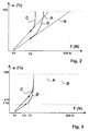
- the deceleration -a is plotted in% (0-100%) over the pedal actuation variable F (N) (z. B. 0-300 N).
- the pedal actuation variable F here preferably corresponds to the pedal force applied by the driver via the brake pedal, which is formed from the admission pressure, which is measured by means of the admission pressure sensor 4 at the output of the master brake cylinder 5.
- the term is used for the pedal actuation quantity F.
- the brake pressure in the wheel brakes HL, HR, VL and VR is generated in such a way that the deceleration gradient increases when the pedal force F rises above the threshold value F2 once the predetermined threshold value F2 of the pedal force F is reached in the sense of an increase in the brake booster ratio corresponding to the deceleration curves C and D compared to the deceleration curves A and B.
- the Desired deceleration curves "with increased deceleration gradients from reaching a predetermined threshold value of the brake pedal force are preferably caused by increasing the wheel brake pressure in a predetermined ratio to the admission pressure, here in the form of a non-linear amplification factor, without necessarily taking into account the delays that arise.
- the amplification factor can be the same in the sense of a control as opposed to a regulation for all delay curves C to D.
- the brake booster effective only when a certain response pedal force F1 is reached becomes. Between the response pedal force F1 and the pedal force threshold F2 can also show deceleration curves between the curves A and B result.
- the brake booster 2 e.g. A or B
- different pedal force threshold values F2 can be defined (not shown in FIG. 2).
- the increased deceleration gradients after the deceleration profiles C and D continue to increase with the further increase in the pedal force F beyond the pedal force threshold value F2. This will be a softer "transition from the initially linear brake booster ratio to the simulated increased brake booster ratio achieved.
- Fig. 3 shows an alternative to the embodiment shown in Fig. 2.
- a target deceleration characteristic curve C is shown, which is preferably empirically determined for the best case and in the control unit 6 is saved.
- the desired deceleration characteristic curve C can also be, as in FIG. 3 shown, from reaching a predetermined pedal force threshold F2 with the further increase in the pedal force F a continuously increasing have increased deceleration gradients. A continuous however, a further increase in the deceleration gradient is not mandatory required.
- Delay threshold -a1 e.g. B. 30% by itself Actual deceleration curve reached the brake booster 2, in the example 3 according to the delay curve B, detected.
- the predetermined delay threshold value -a1 becomes the same Actual pedal force F3 determined at the time.
- the actual delay for the pedal force F3 which corresponds to the predetermined deceleration threshold value -a1 corresponds with the target deceleration corresponding to the target deceleration characteristic C is predetermined for this pedal force F3. Is the actual deceleration is smaller than the target deceleration for the pedal force F3, as shown in Fig.
- the brake pressure in the wheel brakes in the sense of a regulation generates that the target deceleration curve corresponding to the target deceleration characteristic C gives; d. H. the target deceleration curve C is only from reaching a predetermined delay threshold value -a1, here z. B. 30% followed.
- the target deceleration curve C can also first from reaching a predetermined threshold value of the pedal force F, e.g. B. of Threshold F2, are followed (not shown here).
- the target deceleration curve C can also be continuously followed; d.
- the actual deceleration curve is preferably, as shown in FIG. 3 according to a continuously differentiable curve D, z. B. with the help of the definition of a gain factor, to the target deceleration curve C adapted to the through a soft transition To increase the comfort of the braking system.
Landscapes
- Engineering & Computer Science (AREA)
- Transportation (AREA)
- Mechanical Engineering (AREA)
- Physics & Mathematics (AREA)
- Fluid Mechanics (AREA)
- Braking Systems And Boosters (AREA)
- Regulating Braking Force (AREA)
Applications Claiming Priority (2)
| Application Number | Priority Date | Filing Date | Title |
|---|---|---|---|
| DE19743960A DE19743960A1 (de) | 1997-10-04 | 1997-10-04 | Bremsanlage für Kraftfahrzeuge |
| DE19743960 | 1997-10-04 |
Publications (2)
| Publication Number | Publication Date |
|---|---|
| EP0906859A1 true EP0906859A1 (fr) | 1999-04-07 |
| EP0906859B1 EP0906859B1 (fr) | 2003-11-26 |
Family
ID=7844644
Family Applications (1)
| Application Number | Title | Priority Date | Filing Date |
|---|---|---|---|
| EP98116489A Expired - Lifetime EP0906859B1 (fr) | 1997-10-04 | 1998-09-01 | Système de freinage pour véhicules |
Country Status (5)
| Country | Link |
|---|---|
| US (1) | US6212459B1 (fr) |
| EP (1) | EP0906859B1 (fr) |
| JP (1) | JP4227688B2 (fr) |
| DE (2) | DE19743960A1 (fr) |
| ES (1) | ES2212183T3 (fr) |
Cited By (3)
| Publication number | Priority date | Publication date | Assignee | Title |
|---|---|---|---|---|
| EP1108633A1 (fr) * | 1999-12-13 | 2001-06-20 | Toyota Jidosha Kabushiki Kaisha | Dispositif de freinage où la force résultante est plus importante que la valeur de sortie du servomoteur |
| EP1120323A3 (fr) * | 2000-01-26 | 2003-08-06 | Bayerische Motoren Werke Aktiengesellschaft | Système de freinage pour véhicules automobiles |
| WO2010015329A1 (fr) * | 2008-08-06 | 2010-02-11 | Lucas Automotive Gmbh | Procédé et dispositif d’amplification hydraulique de la pression de freinage |
Families Citing this family (24)
| Publication number | Priority date | Publication date | Assignee | Title |
|---|---|---|---|---|
| DE19817326A1 (de) * | 1998-04-18 | 1999-10-21 | Continental Teves Ag & Co Ohg | Verfahren zum Verkürzen des Bremsgeweges |
| US6738601B1 (en) * | 1999-10-21 | 2004-05-18 | Broadcom Corporation | Adaptive radio transceiver with floating MOSFET capacitors |
| JP3700523B2 (ja) * | 2000-02-25 | 2005-09-28 | 株式会社日立製作所 | 倍力装置の制御装置 |
| DE10062978A1 (de) * | 2000-12-16 | 2002-06-20 | Bayerische Motoren Werke Ag | Verfahren und Vorrichtung zur Steuerung der Bremsanlage eines Fahrzeuge |
| JP4590137B2 (ja) * | 2001-08-29 | 2010-12-01 | 本田技研工業株式会社 | 屈曲路走行支援装置 |
| WO2003068575A1 (fr) * | 2002-02-14 | 2003-08-21 | Continental Teves Ag & Co. Ohg | Procede et dispositif pour surveiller et/ou modifier des pressions de freinage |
| DE10335589A1 (de) * | 2003-07-31 | 2005-03-03 | Continental Teves Ag & Co. Ohg | Verfahren zum Betrieb einer Fahrzeugbremsanlage |
| JP4483225B2 (ja) * | 2003-08-21 | 2010-06-16 | 株式会社アドヴィックス | 電気ブレーキ装置 |
| DE102004022993B4 (de) * | 2004-05-10 | 2007-04-05 | Lucas Automotive Gmbh | Bremssystem für ein Fahrzeug und Verfahren zum Ansteuern eines derartigen Bremssystems |
| US20060043790A1 (en) * | 2004-08-27 | 2006-03-02 | Spieker Arnold H | Method for detecting brake circuit failure |
| DE102006028118B4 (de) * | 2006-06-15 | 2016-10-13 | Volkswagen Ag | Bremsanlage in einem Kraftfahrzeug sowie ein dafür geeigneter Sensor |
| US8255103B2 (en) * | 2007-03-27 | 2012-08-28 | GM Global Technology Operations LLC | Electronic brake system pedal release transition control apparatus and method |
| US8364367B2 (en) * | 2007-10-16 | 2013-01-29 | GM Global Technology Operations LLC | Brake assist exit method and system for vehicles |
| US8392088B2 (en) * | 2007-10-16 | 2013-03-05 | GM Global Technology Operations LLC | Brake assist driver command for vehicles |
| US8050836B2 (en) * | 2007-10-17 | 2011-11-01 | GM Global Technology Operations LLC | Method and system for determining initiation of a panic braking maneuver |
| JP4497230B2 (ja) | 2008-05-12 | 2010-07-07 | トヨタ自動車株式会社 | 制動制御装置および制動制御方法 |
| JP5217834B2 (ja) * | 2008-09-22 | 2013-06-19 | トヨタ自動車株式会社 | 牽引時と非牽引時とで制動助勢が異なる牽引駆動車 |
| DE102010042589A1 (de) * | 2010-10-18 | 2012-04-19 | Robert Bosch Gmbh | Verfahren zum automatischen Bremsen eines Fahrzeugs |
| JP5761373B2 (ja) * | 2011-12-14 | 2015-08-12 | トヨタ自動車株式会社 | ブレーキ装置および制動制御装置 |
| DE102012223296A1 (de) * | 2012-12-14 | 2014-06-18 | Continental Teves Ag & Co. Ohg | Verfahren zum Betreiben eines Bremssystems |
| DE102013209006A1 (de) * | 2013-05-15 | 2014-11-20 | Robert Bosch Gmbh | Steuervorrichtung für ein bremskraftverstärktes autonomes Bremssystem eines Fahrzeugs und Verfahren zum Betreiben eines bremskraftverstärkten autonomen Bremssystems eines Fahrzeugs |
| KR102115716B1 (ko) * | 2013-10-07 | 2020-05-27 | 현대모비스 주식회사 | 전자식 유압 브레이크장치 |
| DE102015224601A1 (de) * | 2015-12-08 | 2017-06-08 | Robert Bosch Gmbh | Verfahren und Steuergerät zur Steuerung eines hydraulischen Bremssystems |
| US20250018903A1 (en) * | 2023-07-10 | 2025-01-16 | Independent Driving Systems, Inc. | Effortless readjustable braking system |
Citations (4)
| Publication number | Priority date | Publication date | Assignee | Title |
|---|---|---|---|---|
| DE9110739U1 (de) * | 1990-09-06 | 1991-10-24 | Daimler-Benz Aktiengesellschaft, 7000 Stuttgart | Vorrichtung zur Durchführung eines Verfahrens zur Verkürzung des Bremsweges in kritischen Fahrsituationen |
| WO1993024353A1 (fr) * | 1992-05-26 | 1993-12-09 | Lucas Industries Public Limited Company | Procede de regulation de la pression de freinage au moyen d'un systeme servo |
| DE4440290C1 (de) * | 1994-11-11 | 1995-12-07 | Daimler Benz Ag | Verfahren zur Bestimmung eines Auslöseschwellenwertes für einen automatischen Bremsvorgang |
| DE19615805A1 (de) * | 1996-04-20 | 1997-10-23 | Bosch Gmbh Robert | Verfahren und Vorrichtung zur Steuerung der Bremsanlage eines Fahrzeugs |
Family Cites Families (10)
| Publication number | Priority date | Publication date | Assignee | Title |
|---|---|---|---|---|
| JPS4918675B1 (fr) * | 1969-08-10 | 1974-05-11 | ||
| DE4309850C2 (de) * | 1993-03-26 | 1996-12-12 | Lucas Ind Plc | Bremskraftverstärkersystem zum Regeln eines Bremsdruckes mit einem Bremskraftverstärker |
| DE4329140C1 (de) * | 1993-08-30 | 1994-12-01 | Daimler Benz Ag | Bremsdruck-Steuereinrichtung |
| KR0168492B1 (ko) * | 1994-06-06 | 1998-12-15 | 나까무라 히로까즈 | 차량용 제동 장치 |
| DE19524939C2 (de) * | 1995-07-08 | 1997-08-28 | Bosch Gmbh Robert | Verfahren und Vorrichtung zur Steuerung der Bremsanlage eines Fahrzeugs |
| DE19525985A1 (de) * | 1995-07-17 | 1997-01-23 | Bayerische Motoren Werke Ag | Bremsanlage für Kraftfahrzeuge mit einem Bremskraftverstärker |
| DE19542654A1 (de) * | 1995-11-15 | 1997-05-22 | Lucas Ind Plc | Elektronische steuerbare Bremsanlage für Kraftfahrzeuge |
| DE69602002T2 (de) * | 1996-04-03 | 1999-09-30 | Lucas Industries P.L.C., Solihull | Elektronisch gesteuerter Bremskraftverstärker |
| EP0850815B1 (fr) * | 1996-12-27 | 2002-10-09 | Denso Corporation | Système de freinage pour véhicule |
| DE19743959A1 (de) * | 1997-10-04 | 1999-04-08 | Bayerische Motoren Werke Ag | Bremsanlage für Kraftfahrzeuge |
-
1997
- 1997-10-04 DE DE19743960A patent/DE19743960A1/de not_active Withdrawn
-
1998
- 1998-09-01 EP EP98116489A patent/EP0906859B1/fr not_active Expired - Lifetime
- 1998-09-01 DE DE59810250T patent/DE59810250D1/de not_active Expired - Lifetime
- 1998-09-01 ES ES98116489T patent/ES2212183T3/es not_active Expired - Lifetime
- 1998-10-01 JP JP28002298A patent/JP4227688B2/ja not_active Expired - Fee Related
- 1998-10-05 US US09/166,150 patent/US6212459B1/en not_active Expired - Lifetime
Patent Citations (4)
| Publication number | Priority date | Publication date | Assignee | Title |
|---|---|---|---|---|
| DE9110739U1 (de) * | 1990-09-06 | 1991-10-24 | Daimler-Benz Aktiengesellschaft, 7000 Stuttgart | Vorrichtung zur Durchführung eines Verfahrens zur Verkürzung des Bremsweges in kritischen Fahrsituationen |
| WO1993024353A1 (fr) * | 1992-05-26 | 1993-12-09 | Lucas Industries Public Limited Company | Procede de regulation de la pression de freinage au moyen d'un systeme servo |
| DE4440290C1 (de) * | 1994-11-11 | 1995-12-07 | Daimler Benz Ag | Verfahren zur Bestimmung eines Auslöseschwellenwertes für einen automatischen Bremsvorgang |
| DE19615805A1 (de) * | 1996-04-20 | 1997-10-23 | Bosch Gmbh Robert | Verfahren und Vorrichtung zur Steuerung der Bremsanlage eines Fahrzeugs |
Cited By (6)
| Publication number | Priority date | Publication date | Assignee | Title |
|---|---|---|---|---|
| EP1108633A1 (fr) * | 1999-12-13 | 2001-06-20 | Toyota Jidosha Kabushiki Kaisha | Dispositif de freinage où la force résultante est plus importante que la valeur de sortie du servomoteur |
| US6460944B2 (en) | 1999-12-13 | 2002-10-08 | Toyota Jidosha Kabushiki Kaisha | Braking system wherein brake operating force is made larger than a value corresponding to booster output |
| EP1120323A3 (fr) * | 2000-01-26 | 2003-08-06 | Bayerische Motoren Werke Aktiengesellschaft | Système de freinage pour véhicules automobiles |
| WO2010015329A1 (fr) * | 2008-08-06 | 2010-02-11 | Lucas Automotive Gmbh | Procédé et dispositif d’amplification hydraulique de la pression de freinage |
| CN102143870A (zh) * | 2008-08-06 | 2011-08-03 | 卢卡斯汽车股份有限公司 | 用于液压制动增压的方法和设备 |
| CN102143870B (zh) * | 2008-08-06 | 2015-04-22 | 卢卡斯汽车股份有限公司 | 用于液压制动增压的方法和设备 |
Also Published As
| Publication number | Publication date |
|---|---|
| JP4227688B2 (ja) | 2009-02-18 |
| US6212459B1 (en) | 2001-04-03 |
| DE19743960A1 (de) | 1999-04-08 |
| ES2212183T3 (es) | 2004-07-16 |
| DE59810250D1 (de) | 2004-01-08 |
| JPH11157429A (ja) | 1999-06-15 |
| EP0906859B1 (fr) | 2003-11-26 |
Similar Documents
| Publication | Publication Date | Title |
|---|---|---|
| EP0906859B1 (fr) | Système de freinage pour véhicules | |
| EP0616932B1 (fr) | Système d'assistance au freinage pour régler la pression de freinage au moyen d'un servomoteur | |
| EP0776286B1 (fr) | Procede de regulation de la pression de freinage en fonction de la vitesse d'actionnement de la pedale | |
| EP0824433B1 (fr) | Generateur de valeur de reference | |
| EP1424254A2 (fr) | Méthode pour appliquer un freinage automatique | |
| EP2018302B1 (fr) | Procédé de régulation de la pression de freinage sur les motocyclettes | |
| DE102013216157A1 (de) | Verfahren zur Regelung einer Bremsanlage für Kraftfahrzeuge | |
| DE19750977B4 (de) | Bremsanlage | |
| DE102017211995A1 (de) | Verfahren zum Betreiben einer Bremsanlage eines Kraftfahrzeugs, sowie Steuer- und/oder Regeleinrichtung | |
| EP0906858A1 (fr) | Système de freinage pour véhicules | |
| DE4406128C1 (de) | Verfahren zur Durchführung eines automatischen Bremsvorgangs für eine Kraftfahrzeug-Bremsanlage mit einem Antiblockiersystem | |
| DE102013224967A1 (de) | Verfahren zur Regelung eines elektromechanischen Aktuators sowie Regelvorrichtung | |
| DE19920096B4 (de) | Vorrichtung zur Bremslichtansteuerung | |
| DE69612074T2 (de) | Bremssteuerungsvorrichtung für ein Kraftfahrzeug | |
| DE10124591B4 (de) | Verfahren zum Betreiben eines Bremsassistent-Systems | |
| DE10118635B4 (de) | Verfahren zum Betreiben eines Bremsassistent-Systems | |
| DE102013217579A1 (de) | Verfahren zum Betreiben eines elektromechanischen Bremskraftverstärkers eines Bremssystems, Verfahren zum Betreiben eines rekuperativen Bremssystems und Steuervorrichtung für zumindest einen elektromechanischen Bremskraftverstärker eines Bremssystems | |
| DE69621760T2 (de) | Bremssteuergerät für Fahrzeuge | |
| DE102012222718A1 (de) | Steuervorrichtung für ein Bremssystem eines Fahrzeugs und Verfahren zum Betreiben eines Bremssystems eines Fahrzeugs | |
| DE102012223898A1 (de) | Verfahren zum Betreiben eines hydraulischen Bremssystems eines Kraftfahrzeugs sowie hydraulisches Bremssystem | |
| DE102018213935A1 (de) | Verfahren zum Anpassen eines HBA Schwelldrucks und Vorrichtung zum Durchführen des Verfahrens | |
| DE19822859A1 (de) | Verfahren und Vorrichtung zum Abbremsen eines Fahrzeugs | |
| EP0914998B1 (fr) | Méthode de mise en accord des forces de freinage de deux parties reliées formant un véhicule | |
| DE19545010B4 (de) | Anordnung zur Regelung der Geschwindigkeit eines Kraftfahrzeugs bei ungewollter Beschleunigung | |
| DE19981604B4 (de) | Verfahren zum Betrieb eines Bremsassistent-Systems |
Legal Events
| Date | Code | Title | Description |
|---|---|---|---|
| PUAI | Public reference made under article 153(3) epc to a published international application that has entered the european phase |
Free format text: ORIGINAL CODE: 0009012 |
|
| AK | Designated contracting states |
Kind code of ref document: A1 Designated state(s): DE ES FR GB IT SE |
|
| AX | Request for extension of the european patent |
Free format text: AL;LT;LV;MK;RO;SI |
|
| 17P | Request for examination filed |
Effective date: 19990901 |
|
| AKX | Designation fees paid |
Free format text: DE ES FR GB IT SE |
|
| 17Q | First examination report despatched |
Effective date: 20020403 |
|
| GRAH | Despatch of communication of intention to grant a patent |
Free format text: ORIGINAL CODE: EPIDOS IGRA |
|
| GRAS | Grant fee paid |
Free format text: ORIGINAL CODE: EPIDOSNIGR3 |
|
| GRAA | (expected) grant |
Free format text: ORIGINAL CODE: 0009210 |
|
| AK | Designated contracting states |
Kind code of ref document: B1 Designated state(s): DE ES FR GB IT SE |
|
| REG | Reference to a national code |
Ref country code: GB Ref legal event code: FG4D Free format text: NOT ENGLISH |
|
| GBT | Gb: translation of ep patent filed (gb section 77(6)(a)/1977) |
Effective date: 20031128 |
|
| REF | Corresponds to: |
Ref document number: 59810250 Country of ref document: DE Date of ref document: 20040108 Kind code of ref document: P |
|
| REG | Reference to a national code |
Ref country code: SE Ref legal event code: TRGR |
|
| ET | Fr: translation filed | ||
| REG | Reference to a national code |
Ref country code: ES Ref legal event code: FG2A Ref document number: 2212183 Country of ref document: ES Kind code of ref document: T3 |
|
| PLBE | No opposition filed within time limit |
Free format text: ORIGINAL CODE: 0009261 |
|
| STAA | Information on the status of an ep patent application or granted ep patent |
Free format text: STATUS: NO OPPOSITION FILED WITHIN TIME LIMIT |
|
| 26N | No opposition filed |
Effective date: 20040827 |
|
| REG | Reference to a national code |
Ref country code: FR Ref legal event code: PLFP Year of fee payment: 18 |
|
| PGFP | Annual fee paid to national office [announced via postgrant information from national office to epo] |
Ref country code: ES Payment date: 20150820 Year of fee payment: 18 Ref country code: GB Payment date: 20150924 Year of fee payment: 18 |
|
| PGFP | Annual fee paid to national office [announced via postgrant information from national office to epo] |
Ref country code: SE Payment date: 20150911 Year of fee payment: 18 Ref country code: FR Payment date: 20150928 Year of fee payment: 18 |
|
| PGFP | Annual fee paid to national office [announced via postgrant information from national office to epo] |
Ref country code: IT Payment date: 20150924 Year of fee payment: 18 |
|
| PGFP | Annual fee paid to national office [announced via postgrant information from national office to epo] |
Ref country code: DE Payment date: 20150919 Year of fee payment: 18 |
|
| REG | Reference to a national code |
Ref country code: DE Ref legal event code: R119 Ref document number: 59810250 Country of ref document: DE |
|
| PG25 | Lapsed in a contracting state [announced via postgrant information from national office to epo] |
Ref country code: SE Free format text: LAPSE BECAUSE OF NON-PAYMENT OF DUE FEES Effective date: 20160902 |
|
| REG | Reference to a national code |
Ref country code: SE Ref legal event code: EUG |
|
| GBPC | Gb: european patent ceased through non-payment of renewal fee |
Effective date: 20160901 |
|
| REG | Reference to a national code |
Ref country code: FR Ref legal event code: ST Effective date: 20170531 |
|
| PG25 | Lapsed in a contracting state [announced via postgrant information from national office to epo] |
Ref country code: FR Free format text: LAPSE BECAUSE OF NON-PAYMENT OF DUE FEES Effective date: 20160930 Ref country code: GB Free format text: LAPSE BECAUSE OF NON-PAYMENT OF DUE FEES Effective date: 20160901 Ref country code: DE Free format text: LAPSE BECAUSE OF NON-PAYMENT OF DUE FEES Effective date: 20170401 |
|
| PG25 | Lapsed in a contracting state [announced via postgrant information from national office to epo] |
Ref country code: IT Free format text: LAPSE BECAUSE OF NON-PAYMENT OF DUE FEES Effective date: 20160901 |
|
| PG25 | Lapsed in a contracting state [announced via postgrant information from national office to epo] |
Ref country code: ES Free format text: LAPSE BECAUSE OF NON-PAYMENT OF DUE FEES Effective date: 20160902 |
|
| REG | Reference to a national code |
Ref country code: ES Ref legal event code: FD2A Effective date: 20180625 |