EP0907031A2 - Device for controlling a hydraulic cylinder in a self-propelled harvester - Google Patents
Device for controlling a hydraulic cylinder in a self-propelled harvester Download PDFInfo
- Publication number
- EP0907031A2 EP0907031A2 EP98115143A EP98115143A EP0907031A2 EP 0907031 A2 EP0907031 A2 EP 0907031A2 EP 98115143 A EP98115143 A EP 98115143A EP 98115143 A EP98115143 A EP 98115143A EP 0907031 A2 EP0907031 A2 EP 0907031A2
- Authority
- EP
- European Patent Office
- Prior art keywords
- pump
- hydraulic cylinder
- valve
- variable displacement
- control unit
- Prior art date
- Legal status (The legal status is an assumption and is not a legal conclusion. Google has not performed a legal analysis and makes no representation as to the accuracy of the status listed.)
- Granted
Links
- 239000012530 fluid Substances 0.000 claims abstract description 5
- 238000006073 displacement reaction Methods 0.000 claims description 24
- 230000001419 dependent effect Effects 0.000 claims description 7
- 238000005086 pumping Methods 0.000 claims description 2
- 241001124569 Lycaenidae Species 0.000 description 2
- 238000010586 diagram Methods 0.000 description 2
- 238000011144 upstream manufacturing Methods 0.000 description 2
- 230000000694 effects Effects 0.000 description 1
Images

Classifications
-
- F—MECHANICAL ENGINEERING; LIGHTING; HEATING; WEAPONS; BLASTING
- F15—FLUID-PRESSURE ACTUATORS; HYDRAULICS OR PNEUMATICS IN GENERAL
- F15B—SYSTEMS ACTING BY MEANS OF FLUIDS IN GENERAL; FLUID-PRESSURE ACTUATORS, e.g. SERVOMOTORS; DETAILS OF FLUID-PRESSURE SYSTEMS, NOT OTHERWISE PROVIDED FOR
- F15B11/00—Servomotor systems without provision for follow-up action; Circuits therefor
- F15B11/16—Servomotor systems without provision for follow-up action; Circuits therefor with two or more servomotors
-
- F—MECHANICAL ENGINEERING; LIGHTING; HEATING; WEAPONS; BLASTING
- F15—FLUID-PRESSURE ACTUATORS; HYDRAULICS OR PNEUMATICS IN GENERAL
- F15B—SYSTEMS ACTING BY MEANS OF FLUIDS IN GENERAL; FLUID-PRESSURE ACTUATORS, e.g. SERVOMOTORS; DETAILS OF FLUID-PRESSURE SYSTEMS, NOT OTHERWISE PROVIDED FOR
- F15B21/00—Common features of fluid actuator systems; Fluid-pressure actuator systems or details thereof, not covered by any other group of this subclass
- F15B21/08—Servomotor systems incorporating electrically operated control means
- F15B21/087—Control strategy, e.g. with block diagram
-
- F—MECHANICAL ENGINEERING; LIGHTING; HEATING; WEAPONS; BLASTING
- F15—FLUID-PRESSURE ACTUATORS; HYDRAULICS OR PNEUMATICS IN GENERAL
- F15B—SYSTEMS ACTING BY MEANS OF FLUIDS IN GENERAL; FLUID-PRESSURE ACTUATORS, e.g. SERVOMOTORS; DETAILS OF FLUID-PRESSURE SYSTEMS, NOT OTHERWISE PROVIDED FOR
- F15B2211/00—Circuits for servomotor systems
- F15B2211/20—Fluid pressure source, e.g. accumulator or variable axial piston pump
- F15B2211/205—Systems with pumps
- F15B2211/2053—Type of pump
- F15B2211/20546—Type of pump variable capacity
-
- F—MECHANICAL ENGINEERING; LIGHTING; HEATING; WEAPONS; BLASTING
- F15—FLUID-PRESSURE ACTUATORS; HYDRAULICS OR PNEUMATICS IN GENERAL
- F15B—SYSTEMS ACTING BY MEANS OF FLUIDS IN GENERAL; FLUID-PRESSURE ACTUATORS, e.g. SERVOMOTORS; DETAILS OF FLUID-PRESSURE SYSTEMS, NOT OTHERWISE PROVIDED FOR
- F15B2211/00—Circuits for servomotor systems
- F15B2211/40—Flow control
- F15B2211/405—Flow control characterised by the type of flow control means or valve
- F15B2211/40507—Flow control characterised by the type of flow control means or valve with constant throttles or orifices
-
- F—MECHANICAL ENGINEERING; LIGHTING; HEATING; WEAPONS; BLASTING
- F15—FLUID-PRESSURE ACTUATORS; HYDRAULICS OR PNEUMATICS IN GENERAL
- F15B—SYSTEMS ACTING BY MEANS OF FLUIDS IN GENERAL; FLUID-PRESSURE ACTUATORS, e.g. SERVOMOTORS; DETAILS OF FLUID-PRESSURE SYSTEMS, NOT OTHERWISE PROVIDED FOR
- F15B2211/00—Circuits for servomotor systems
- F15B2211/40—Flow control
- F15B2211/415—Flow control characterised by the connections of the flow control means in the circuit
- F15B2211/41509—Flow control characterised by the connections of the flow control means in the circuit being connected to a pressure source and a directional control valve
-
- F—MECHANICAL ENGINEERING; LIGHTING; HEATING; WEAPONS; BLASTING
- F15—FLUID-PRESSURE ACTUATORS; HYDRAULICS OR PNEUMATICS IN GENERAL
- F15B—SYSTEMS ACTING BY MEANS OF FLUIDS IN GENERAL; FLUID-PRESSURE ACTUATORS, e.g. SERVOMOTORS; DETAILS OF FLUID-PRESSURE SYSTEMS, NOT OTHERWISE PROVIDED FOR
- F15B2211/00—Circuits for servomotor systems
- F15B2211/40—Flow control
- F15B2211/45—Control of bleed-off flow, e.g. control of bypass flow to the return line
-
- F—MECHANICAL ENGINEERING; LIGHTING; HEATING; WEAPONS; BLASTING
- F15—FLUID-PRESSURE ACTUATORS; HYDRAULICS OR PNEUMATICS IN GENERAL
- F15B—SYSTEMS ACTING BY MEANS OF FLUIDS IN GENERAL; FLUID-PRESSURE ACTUATORS, e.g. SERVOMOTORS; DETAILS OF FLUID-PRESSURE SYSTEMS, NOT OTHERWISE PROVIDED FOR
- F15B2211/00—Circuits for servomotor systems
- F15B2211/40—Flow control
- F15B2211/455—Control of flow in the feed line, i.e. meter-in control
-
- F—MECHANICAL ENGINEERING; LIGHTING; HEATING; WEAPONS; BLASTING
- F15—FLUID-PRESSURE ACTUATORS; HYDRAULICS OR PNEUMATICS IN GENERAL
- F15B—SYSTEMS ACTING BY MEANS OF FLUIDS IN GENERAL; FLUID-PRESSURE ACTUATORS, e.g. SERVOMOTORS; DETAILS OF FLUID-PRESSURE SYSTEMS, NOT OTHERWISE PROVIDED FOR
- F15B2211/00—Circuits for servomotor systems
- F15B2211/60—Circuit components or control therefor
- F15B2211/63—Electronic controllers
- F15B2211/6303—Electronic controllers using input signals
-
- F—MECHANICAL ENGINEERING; LIGHTING; HEATING; WEAPONS; BLASTING
- F15—FLUID-PRESSURE ACTUATORS; HYDRAULICS OR PNEUMATICS IN GENERAL
- F15B—SYSTEMS ACTING BY MEANS OF FLUIDS IN GENERAL; FLUID-PRESSURE ACTUATORS, e.g. SERVOMOTORS; DETAILS OF FLUID-PRESSURE SYSTEMS, NOT OTHERWISE PROVIDED FOR
- F15B2211/00—Circuits for servomotor systems
- F15B2211/60—Circuit components or control therefor
- F15B2211/665—Methods of control using electronic components
- F15B2211/6652—Control of the pressure source, e.g. control of the swash plate angle
-
- F—MECHANICAL ENGINEERING; LIGHTING; HEATING; WEAPONS; BLASTING
- F15—FLUID-PRESSURE ACTUATORS; HYDRAULICS OR PNEUMATICS IN GENERAL
- F15B—SYSTEMS ACTING BY MEANS OF FLUIDS IN GENERAL; FLUID-PRESSURE ACTUATORS, e.g. SERVOMOTORS; DETAILS OF FLUID-PRESSURE SYSTEMS, NOT OTHERWISE PROVIDED FOR
- F15B2211/00—Circuits for servomotor systems
- F15B2211/70—Output members, e.g. hydraulic motors or cylinders or control therefor
- F15B2211/71—Multiple output members, e.g. multiple hydraulic motors or cylinders
- F15B2211/7142—Multiple output members, e.g. multiple hydraulic motors or cylinders the output members being arranged in multiple groups
-
- F—MECHANICAL ENGINEERING; LIGHTING; HEATING; WEAPONS; BLASTING
- F15—FLUID-PRESSURE ACTUATORS; HYDRAULICS OR PNEUMATICS IN GENERAL
- F15B—SYSTEMS ACTING BY MEANS OF FLUIDS IN GENERAL; FLUID-PRESSURE ACTUATORS, e.g. SERVOMOTORS; DETAILS OF FLUID-PRESSURE SYSTEMS, NOT OTHERWISE PROVIDED FOR
- F15B2211/00—Circuits for servomotor systems
- F15B2211/70—Output members, e.g. hydraulic motors or cylinders or control therefor
- F15B2211/78—Control of multiple output members
Definitions
- the invention relates to a device for controlling a Hydraulic cylinders in a self-propelled harvester with a variable displacement pump for pumping a hydraulic fluid and with at least one associated with the hydraulic cylinder Valve.
- a hydraulic control circuit For actuating hydraulic cylinders, for example a header of a harvester or a conveyor of the same a hydraulic control circuit is known, which has variable pumps and proportional directional valves and depending on the particular need one with the Hydraulic cylinder connected consumer a corresponding Funding volume.
- the object of the invention is therefore to provide a device for Control of a hydraulic cylinder in a self-propelled Harvester specify which is a simple, inexpensive and effective control of hydraulic cylinders guaranteed.
- the invention is characterized in that that the valve is designed as a switching valve and that the switching valve and the variable displacement pump are so electric can be controlled that that supplied by the variable displacement pump Delivery volume to the requirements of the hydraulic cylinder is adjusted.
- the particular advantage of the invention is that the required quickly and to a sufficient extent on request Delivery volume for actuating the hydraulic cylinder can be provided. This is made possible through the combination of a fast-switching switching valve and a variable displacement pump, each of which can be operated electrically are.
- variable displacement pump on the one hand and the switching valve on the other hand with a electrical control unit connected, the means for Generation of control signals depending on a predetermined Has actuation signal.
- the electrical control unit enables the need-based control of the Variable pump, so that a consumer-dependent control of the correspondingly assigned hydraulic cylinder is effected.
- the electrical Control unit a pump control signal, which is a stepless Setting the delivery volume supplied by the variable pump enables. This can make the different Speed and length requirements of the stroke are taken into account.
- the electrical Control unit means for storing control curves for several hydraulic cylinders so that hydraulic cylinders are automatically operated in the specified order can.
- the switching valves upstream of each a current valve by means of which the flow to the respective hydraulic cylinders can be adjusted.
- a flow valve is preferred designed as a 3-way flow control valve that one is assigned to the first hydraulic cylinder, with a constant Volume flow branched off to further hydraulic cylinders becomes.
- the device according to the invention can be used to actuate Used by self-propelled harvesters become. For example, a header in moved vertically or around a horizontal axis be pivoted. Furthermore, the device for actuation a swiveling grain tank outlet pipe, conveyor or feeder for the crop or for the Swiveling a cultivator used as a consumer become.
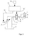
- a variable displacement pump 2 is intended to convey a hydraulic fluid in a Delivery line 3 from a tank 4 to a switching valve 5.
- the switching valve 5 is by means of another delivery line 6 connected to a connection of the hydraulic cylinder 1.
- One on the opposite side of the hydraulic cylinder 1 connected drain line 7 carries the hydraulic fluid pressureless back via the switching valve 5 the tank 4.
- the hydraulic cylinder 1 has a piston rod 8 with a on the same piston 9 connected at the end, which is movable are stored in the hydraulic cylinder 1.
- a free one The end of the piston rod 8 extends outside the hydraulic cylinder 1 and is with a not shown Connected consumers.
- the variable displacement pump 2 is designed as an axial piston pump and is electrically operated.
- the variable displacement pump is for this purpose 2 through an electrical line 10 with a electrical control unit 11 electrically connected.
- the Switch valve 5 is designed as a 4/3-way valve and is electromagnetic actuatable.
- the switching valve 5 an electrical connecting line 12 to the electrical control unit 11.
- the control unit 11 is electrically connected on the input side to a key element 13, preferably in a cab of the harvester is arranged.
- a consumer connected to the hydraulic cylinder 1 in a predetermined position By pressing the button element 13, for example a consumer connected to the hydraulic cylinder 1 in a predetermined position can be pivoted.
- the key element 13 gives an actuation signal to the control unit 11, the means for generating a pump control signal on the one hand and for generating a valve control signal on the other hand.
- the pump control signal is via the electrical line 10 to the variable displacement pump 2 transmitted, the size of the pump control signal to one consumer-dependent volume flow corresponds.
- the the switching valve via the electrical connecting line 12 5 Actuating valve control signal switches valve 5 such that the piston 9 moves in a predetermined direction becomes.
- control unit 11 can also be used for control purposes serve several variable pumps 2 or switching valves 5, wherein consumer-dependent data of the respective variable pumps 2 and valves 5 are assigned.
- electrical control unit 11 an integrated circuit on.
- an electrical control unit 15 is provided for the control a variable displacement pump 16 and several switching valves 17, 17 ', 17' 'is used.
- the control unit 15 via a control line 18 with the variable displacement pump 16 and Control lines 19, 19 ', 19' 'with the switching valves 17, 17 ', 17' 'connected.
- the variable displacement pump 16 is on the pressure side connected to a 3-way flow control valve 20, the first Output via the switching valve 17 with a first hydraulic cylinder 21 is connected.
- a second exit of the 3-way flow control valve 20 is each via a 2-way flow control valve 22, 22 'and corresponding switching valves 17 ', 17' 'with a second hydraulic cylinder 21' or a third hydraulic cylinder 21 ''.
- the 3-way flow control valve 20 is designed such that a constant Volume flow in the direction of the two hydraulic cylinders 21 ', 21' 'is branched, the 2-way flow control valves 22, 22 'have an even distribution Hydraulic cylinder 21 ', 21' 'effect.
- the control unit 15 is in each case with a Key element 23, a lever element 24 and a multi-function handle 25 connected as input elements.
- These input elements 23, 24, 25 are each a hydraulic cylinder 21, 21 ', 21' 'assigned.
- Pump control signal such a level that a needs-based Volume flow is generated by means of a valve control signal the control unit 15 addressed Switching valve 17 to the hydraulic cylinder 21 is promoted.
- all input elements 23, 24, 25 is a correspondingly higher pump control signal to the Variable pump 16 delivered.
- the 3-way flow control valve 20 guaranteed in connection with the 2-way flow control valves 22, 22 ' an even distribution of the volume flow to the hydraulic cylinders 21, 21 ', 21' '.
- a sensor 26 with the electrical control unit 15 be electrically connected, so that depending a specific hydraulic cylinder from a sensor signal 21, 21 ', 21' 'is addressed.
- the contour of the ground is detected by means of the sensor 26 be, a corresponding in the control unit 15 long pump control signal of a certain height and a corresponding one Valve assigned control signal generated is, so that the assigned according to the cutting unit Hydraulic cylinders ensure a certain cutting height can.
- the control unit 15 has a microcontroller 28 on, in which the arithmetic operations for generation of the control signals are carried out. Farther can in a memory of the microcontroller 28 consumer-dependent Control data must be stored when there is a change or extension of the consumers to be operated can be.
- the senor 26 can be used together with the multifunction handle 25 to a first hydraulic cylinder 21 Act.
- the sensor signal causes a presetting the cutting unit if there is an uneven floor.
- the sensor 26 is used in cooperation with the control unit 15 as an actuator, while later or at the same time an exact setting of the consumer is done manually. That way, faster to be reacted to external interference, the operator is relieved in its concentration.
- the multi-function handle 25 with the control unit 15 be connected such that by pressing one Button 30 of the multi-function handle 25 a the hydraulic cylinder 21 controlling pump control signal is given, meanwhile by additionally pivoting the handle 29 the speed of movement of the piston 9 of the Hydraulic cylinder 21 is affected. For example by moving the handle 29 from a zero position forward an increased speed of the piston in a first direction and by moving the handle 29 after rear increased piston speed into one opposite direction. To this end becomes dependent on the control signal of the multifunction handle 25 a corresponding pump control signal to the Pump that is continuously adjustable and a correspondingly adjusted volume flow generated.
- circuitry linking the Variable pump 2 on the one hand with the Sachlt valve 5 on the other is that noises due to movements of the Hydraulic lines 3, 6, 7 or more in the case of strong pressure fluctuations largely avoided in the hydraulic circuit become.
- the invention is not based on the specified number of hydraulic cylinders limited. Of course it can other consumers connected to the hydraulic circuit be, with appropriate flow control valves upstream are.
- variable displacement pump 2 can be replaced by a ramp-shaped one Pump control signal can be controlled, with a predetermined The piston stroke of the variable displacement pump 2 is fixed becomes.
- the piston of the variable displacement pump 2 is here after a certain characteristic in one direction and then again moved in the opposite direction. After that you can the corresponding switching valve can be switched off.
Landscapes
- Engineering & Computer Science (AREA)
- Physics & Mathematics (AREA)
- Fluid Mechanics (AREA)
- Mechanical Engineering (AREA)
- General Engineering & Computer Science (AREA)
- Chemical & Material Sciences (AREA)
- Analytical Chemistry (AREA)
- Fluid-Pressure Circuits (AREA)
- Control Of Positive-Displacement Pumps (AREA)
- Lifting Devices For Agricultural Implements (AREA)
Abstract
Description
Die Erfindung betrifft eine Vorrichtung zur Steuerung eines Hydraulikzylinders in einer selbstfahrenden Erntemaschine mit einer Verstellpumpe zum Fördern einer Hydraulikflüssigkeit und mit mindestens einem dem Hydraulikzylinder zugeordneten Ventil.The invention relates to a device for controlling a Hydraulic cylinders in a self-propelled harvester with a variable displacement pump for pumping a hydraulic fluid and with at least one associated with the hydraulic cylinder Valve.
Zur Betätigung von Hydraulikzylindern, denen beispielsweise ein Vorsatz einer Erntemaschine oder ein Förderer derselben zugeordnet ist, ist ein hydraulischer Regelkreis bekannt, der Verstellpumpen und proportionale Wegeventile aufweist und in Abhängigkeit von dem jeweiligen Bedarf eines mit dem Hydraulikzylinder verbundenen Verbrauchers ein entsprechendes Fördervolumen einstellt.For actuating hydraulic cylinders, for example a header of a harvester or a conveyor of the same a hydraulic control circuit is known, which has variable pumps and proportional directional valves and depending on the particular need one with the Hydraulic cylinder connected consumer a corresponding Funding volume.
Ferner ist aus der WO 97 02 432 A1 ein hydraulischer Regelkreis bekannt, der in Abhängigkeit von mehreren Zustandsgrößen die Stellung eines Steuerventils einerseits und den von der Pumpe gelieferten Volumenstrom andererseits derart bestimmt, daß der Kolben des Hydraulikzylinders eine gewünschte Lage einnimmt. Die aus dem Stand der Technik bekannten Vorrichtungen weisen jedoch den Nachteil auf, daß sie für den Einsatz in selbstfahrenden Erntemaschinen relativ aufwendig und kostenintensiv sind.Furthermore, from WO 97 02 432 A1 is a hydraulic control circuit known, depending on several state variables the position of a control valve on the one hand and the Volume flow supplied by the pump on the other hand determines that the piston of the hydraulic cylinder has a desired one Takes position. The known from the prior art However, devices have the disadvantage that relative for use in self-propelled harvesters are complex and costly.
Aufgabe der Erfindung ist es daher, eine Vorrichtung zur Steuerung eines Hydraulikzylinders in einer selbstfahrenden Erntemaschine anzugeben, die auf einfache Weise eine kostengünstige und effektive Steuerung von Hydraulikzylindern gewährleistet.The object of the invention is therefore to provide a device for Control of a hydraulic cylinder in a self-propelled Harvester specify which is a simple, inexpensive and effective control of hydraulic cylinders guaranteed.
Zur Lösung dieser Aufgabe ist die Erfindung dadurch gekennzeichnet, daß das Ventil als Schaltventil ausgebildet ist und daß das Schaltventil und die Verstellpumpe derart elektrisch ansteuerbar sind, daß das von der Verstellpumpe gelieferte Fördervolumen an den Bedarf des Hydraulikzylinders angepaßt ist.To achieve this object, the invention is characterized in that that the valve is designed as a switching valve and that the switching valve and the variable displacement pump are so electric can be controlled that that supplied by the variable displacement pump Delivery volume to the requirements of the hydraulic cylinder is adjusted.
Der besondere Vorteil der Erfindung ist darin zu sehen, daß auf Anforderung schnell und in ausreichendem Maße das erforderliche Fördervolumen zur Betätigung des Hydraulikzylinders bereitgestellt werden kann. Dies wird ermöglicht durch die Kombination eines schnellschaltenden Schaltventils und einer Verstellpumpe, die jeweils elektrisch betätigbar sind.The particular advantage of the invention is that the required quickly and to a sufficient extent on request Delivery volume for actuating the hydraulic cylinder can be provided. This is made possible through the combination of a fast-switching switching valve and a variable displacement pump, each of which can be operated electrically are.
Nach einer Ausgestaltung der Erfindung sind die Verstellpumpe einerseits und das Schaltventil andererseits mit einer elektrischen Steuereinheit verbunden, die Mittel zur Erzeugung von Stellsignalen in Abhängigkeit von einem vorgegebenen Betätigungssignal aufweist. Die elektrische Steuereinheit ermöglicht eine bedarfsgerechte Ansteuerung der Verstellpumpe, so daß zentral eine verbraucherabhängige Ansteuerung des entsprechend zugeordneten Hydraulikzylinders bewirkt wird.According to one embodiment of the invention, the variable displacement pump on the one hand and the switching valve on the other hand with a electrical control unit connected, the means for Generation of control signals depending on a predetermined Has actuation signal. The electrical control unit enables the need-based control of the Variable pump, so that a consumer-dependent control of the correspondingly assigned hydraulic cylinder is effected.
Nach einer Weiterbildung der Erfindung erzeugt die elektrische Steuereinheit ein Pumpen-Stellsignal, das eine stufenlose Einstellung des von der Verstellpumpe gelieferten Fördervolumens ermöglicht. Hierdurch kann den unterschiedlichen Anforderungen hinsichtlich Geschwindigkeit und Länge des Hubes Rechnung getragen werden.According to a development of the invention, the electrical Control unit a pump control signal, which is a stepless Setting the delivery volume supplied by the variable pump enables. This can make the different Speed and length requirements of the stroke are taken into account.
Nach einer Weiterbildung der Erfindung weist die elektrische Steuereinheit Mittel zur Speicherung von Steuerkurven für mehrere Hydraulikzylinder auf, so daß Hydraulikzylinder automatisch in vorgegebener Reihenfolge betätigt werden können.According to a development of the invention, the electrical Control unit means for storing control curves for several hydraulic cylinders so that hydraulic cylinders are automatically operated in the specified order can.
Nach einer Weiterbildung der Erfindung sind den Schaltventilen jeweils ein Stromventil vorgeschaltet, mittels dessen der zu den jeweiligen Hydraulikzylindern geleitete Förderstrom eingestellt werden kann. Vorzugsweise ist ein Stromventil als 3-Wege-Stromregelventil ausgebildet, das einem ersten Hydraulikzylinder zugeordnet ist, wobei ein konstanter Volumenstrom zu weiteren Hydraulikzylindern abgezweigt wird.According to a development of the invention, the switching valves upstream of each a current valve, by means of which the flow to the respective hydraulic cylinders can be adjusted. A flow valve is preferred designed as a 3-way flow control valve that one is assigned to the first hydraulic cylinder, with a constant Volume flow branched off to further hydraulic cylinders becomes.
Zwei Ausführungsbeispiele der Erfindung werden nachfolgend anhand der Zeichnungen näher erläutert. Two embodiments of the invention are as follows explained in more detail with reference to the drawings.
Es zeigen:
- Figur 1:
- ein Blockschaltbild der Vorrichtung nach einem ersten Ausführungsbeispiel und
- Figur 2:
- ein Blockschaltbild der Vorrichtung nach einem zweiten Ausführungsbeispiel.
- Figure 1:
- a block diagram of the device according to a first embodiment and
- Figure 2:
- a block diagram of the device according to a second embodiment.
Die erfindungsgemäße Vorrichtung kann zur Betätigung von Verbrauchern von selbstfahrenden Erntemaschinen verwendet werden. Beispielsweise kann ein Erntemaschinenvorsatz in vertikaler Richtung bewegt oder um eine horizontale Achse verschwenkt werden. Weiterhin kann die Vorrichtung zur Betätigung eines schwenkbaren Korntankauslaufrohres, Förderers bzw. Schrägförderers für das Erntegut oder für das Verschwenken eines Anbauhäckslers als Verbraucher verwendet werden.The device according to the invention can be used to actuate Used by self-propelled harvesters become. For example, a header in moved vertically or around a horizontal axis be pivoted. Furthermore, the device for actuation a swiveling grain tank outlet pipe, conveyor or feeder for the crop or for the Swiveling a cultivator used as a consumer become.
Nach einem ersten Ausführungsbeispiel gemäß Figur 1 weist
die Vorrichtung einen einzigen Hydraulikzylinder 1 auf zur
Betätigung eines Verbrauchers. Eine Verstellpumpe 2 ist
vorgesehen zur Förderung einer Hydraulikflüssigkeit in einer
Förderleitung 3 von einem Tank 4 zu einem Schaltventil
5. Das Schaltventil 5 ist mittels einer weiteren Förderleitung
6 mit einem Anschluß des Hydraulikzylinders 1 verbunden.
Eine auf der gegenüberliegenden Seite des Hydraulikzylinders
1 angeschlossene Ablaufleitung 7 führt die Hydraulikflüssigkeit
drucklos über das Schaltventil 5 zurück zu
dem Tank 4. According to a first embodiment according to FIG. 1
the device to a single hydraulic cylinder 1
Operation of a consumer. A
Der Hydraulikzylinder 1 weist eine Kolbenstange 8 mit einem
an demselben endseitig anschließenden Kolben 9 auf, die beweglich
in dem Hydraulikzylinder 1 gelagert sind. Ein freies
Ende der Kolbenstange 8 erstreckt sich außerhalb des Hydraulikzylinders
1 und ist mit einem nicht dargestellten
Verbraucher wirkverbunden.The hydraulic cylinder 1 has a
Die Verstellpumpe 2 ist als Axialkolbenpumpe ausgebildet
und ist elektrisch betätigbar. Zu diesem Zweck ist die Verstellpumpe
2 durch eine elektrische Leitung 10 mit einer
elektrischen Steuereinheit 11 elektrisch verbunden. Das
Schaltventil 5 ist als 4/3-Wegeventil ausgebildet und elektromagnetisch
betätigbar. Zu diesem Zweck weist das Schaltventil
5 eine elektrische Verbindungsleitung 12 zu der
elektrischen Steuereinheit 11 auf. Die Steuereinheit 11 ist
eingangsseitig mit einem Tastenelement 13 elektrisch verbunden,
das vorzugsweise in einem Führerhaus der Erntemaschine
angeordnet ist.The
Durch Betätigung des Tastenelements 13 kann beispielsweise
ein mit dem Hydraulikzylinder 1 verbundener Verbraucher in
eine vorgegebene Position verschwenkt werden. Das Tastenelement
13 gibt ein Betätigungssignal an die Steuereinheit
11 ab, das Mittel zur Erzeugung eines Pumpen-Stellsignals
einerseits und zur Erzeugung eines Ventil-Stellsignals
andererseits aufweist. Das Pumpen-Stellsignal
wird über die elektrische Leitung 10 an die Verstellpumpe 2
übertragen, wobei die Größe des Pumpen-Stellsignals zu einem
verbraucherabhängigen Volumenstrom korrespondiert. Das
über die elektrische Verbindungsleitung 12 das Schaltventil
5 beaufschlagende Ventil-Stellsignal schaltet das Ventil 5
derart, daß der Kolben 9 in eine vorgegebene Richtung bewegt
wird.By pressing the
Alternativ kann die Steuereinheit 11 auch zur Steuerung
mehrerer Verstellpumpen 2 bzw. Schaltventile 5 dienen, wobei
verbraucherabhängige Daten den jeweiligen Verstellpumpen
2 und Ventilen 5 zugeordnet sind. Zu diesem Zweck weist
die elektrische Steuereinheit 11 einen integrierten Schaltkreis
auf.Alternatively, the
Nach einem zweiten Ausführungsbeispiel gemäß Figur 2 ist
eine elektrische Steuereinheit 15 vorgesehen, die zur Ansteuerung
einer Verstellpumpe 16 und mehrerer Schaltventile
17, 17', 17'' dient. Zu diesem Zweck ist die Steuereinheit
15 über eine Steuerleitung 18 mit der Verstellpumpe 16 und
Steuerleitungen 19, 19', 19'' mit den Schaltventilen 17,
17', 17'' verbunden. Die Verstellpumpe 16 ist druckseitig
mit einem 3-Wege-Stromregelventil 20 verbunden, dessen erster
Ausgang über das Schaltventil 17 mit einem ersten Hydraulikzylinder
21 verbunden ist. Ein zweiter Ausgang des
3-Wege-Stromregelventils 20 ist jeweils über ein 2-Wege-Stromregelventil
22, 22' sowie entsprechenden Schaltventilen
17', 17'' mit einem zweiten Hydraulikzylinder 21' bzw.
einem dritten Hydraulikzylinder 21'' verbunden. Das 3-Wege-Stromregelventil
20 ist derart ausgebildet, daß ein konstanter
Volumenstrom in Richtung der beiden Hydraulikzylinder
21', 21'' abgezweigt wird, wobei die 2-Wege-Stromregelventile
22, 22' eine gleichmäßige Verteilung auf
Hydraulikzylinder 21', 21'' bewirken.According to a second embodiment according to FIG
an electrical control unit 15 is provided for the control
a
Eingangsseitig ist die Steuereinheit 15 jeweils mit einem
Tastenelement 23, einem Hebelelement 24 und einem Multifunktionsgriff
25 als Eingabeelemente verbunden. Diese Eingabeelemente
23, 24, 25 sind jeweils einem Hydraulikzylinder
21, 21', 21'' zugeordnet. Bei Ansteuerung eines einzigen
Hydraulikzylinders 21 mittels Betätigung des Tastenelements
23 erfolgt ein an die Verstellpumpe 16 gerichtetes
Pumpen-Stellsignals solcher Höhe, daß ein bedarfsgerechter
Volumenstrom erzeugt wird, der über ein mittels eines Ventil-Stellsignals
der Steuereinheit 15 angesprochenes
Schaltventil 17 zu dem Hydraulikzyliner 21 gefördert wird.
Bei gleichzeitiger Betätigung aller Eingabeelemente 23, 24,
25 wird ein entsprechend höheres Pumpen-Stellsignal an die
Verstellpumpe 16 abgegeben. Das 3-Wege-Stromregelventil 20
in Verbindung mit den 2-Wege-Stromregelventilen 22, 22' gewährleistet
eine gleichmäßige Verteilung des Volumenstroms
an die Hydraulikzylinder 21, 21', 21''.On the input side, the control unit 15 is in each case with a
Zusätzlich kann ein Sensor 26 mit der elektrischen Steuereinheit
15 elektrisch verbunden sein, so daß in Abhängigkeit
von einem Sensorsignal ein bestimmter Hydraulikzylinder
21, 21', 21'' angesprochen wird. Beispielsweise kann
mittels des Sensors 26 die Kontur des Bodens detektiert
werden, wobei in der Steuereinheit 15 ein korrespondierend
langes Pumpen-Stellsignal bestimmter Höhe und ein dem entsprechenden
Ventil zugeordnetes Ventil-Stellsignal erzeugt
wird, so daß der entsprechend dem Schneidwerk zugeordnete
Hydraulikzylinder eine bestimmte Schnitthöhe gewährleisten
kann. Zu diesem Zweck weist die Steuereinheit 15 einen Mikrocontroller
28 auf, in dem die Rechenoperationen zur Erzeugung
der Stellsignale durchgeführt werden. Weiterhin
können in einem Speicher des Mikrocontrollers 28 verbraucherabhängige
Steuerungsdaten abgelegt sein, die bei Änderung
oder Erweiterung der zu betätigenden Verbraucher herangezogen
werden können.In addition, a
Beispielsweise kann der Sensor 26 zusammen mit dem Multifunktionsgriff
25 auf einen ersten Hydraulikzylinder 21
wirken. Dabei bewirkt das Sensorsignal eine Voreinstellung
des Schneidwerks bei Vorliegen einer Bodenunebenheit. Mittels
des Multifunktionsgriffs 25 kann die Bedienperson die
Richtung der Schneidwerkbewegung korrigierend durch Verschwenken
eines Haltegriffs 29 des Multifunktionsgriffs 25
in eine oder in eine entgegengesetzte Richtung nachstellen.
Bei dieser Ausführung dient der Sensor 26 im Zusammenwirken
mit der Steuereinheit 15 als Vorstellglied, während später
oder gleichzeitig eine genaue Einstellung des Verbrauchers
manuell vorgenommen wird. Auf diese Weise kann schneller
auf äußere Störeinflüsse reagiert werden, wobei die Bedienperson
in seiner Konzentration entlastet wird.For example, the
Alternativ kann der Multifunktionsgriff 25 mit der Steuereinheit
15 derart verbunden sein, daß durch Drücken einer
Taste 30 des Multifunktionsgriffs 25 ein den Hydraulikzylinder
21 steuerndes Pumpen-Stellsignal abgegeben wird,
währenddessen durch Verschwenken des Haltegriffes 29 zusätzlich
die Geschwindigkeit der Bewegung des Kolbens 9 des
Hydraulikzylinders 21 beeinflußt wird. Beispielsweise kann
durch Bewegung des Haltegriffes 29 aus einer Nullstellung
nach vorne eine erhöhte Geschwindigkeit des Kolbens in eine
erste Richtung und durch Bewegung des Haltegriffs 29 nach
hinten eine erhöhte Geschwindigkeit des Kolbens in eine
entgegengesetzte Richtung bewirkt werden. Zu diesem Zweck
wird in Abhängigkeit von dem Steuersignal des Multifunktionsgriffs
25 ein entsprechendes Pumpen-Stellsignal an die
Pumpe abgegeben, die stufenlos einstellbar ist und einen
entsprechend angepaßten Volumentstrom erzeugt.Alternatively, the
Ein weiterer Vorteil der nach der erfindungsgemäßen Vorrichtung
vorgesehenen schaltungstechnischen Verknüpfung der
Verstellpumpe 2 einerseits mit dem Sachltventil 5 andererseits
liegt darin, daß Geräusche infolge von Bewegungen der
Hydraulikleitungen 3, 6, 7 oder weiteren bei starken Druckschwankungen
in dem Hydraulikkreis weitgehend vermieden
werden.Another advantage of the device according to the invention
provided circuitry linking the
Die Erfindung ist nicht auf die angegebene Anzahl von Hydraulikzylindern beschränkt. Es können selbstverständlich noch weitere Verbraucher an den Hydraulikkreis angeschlossen werden, wobei entsprechende Stromregelventile vorgeschaltet sind.The invention is not based on the specified number of hydraulic cylinders limited. Of course it can other consumers connected to the hydraulic circuit be, with appropriate flow control valves upstream are.
Alternativ kann die Verstellpumpe 2 durch ein rampenförmiges
Pumpen-Stellsignal angesteuert werden, wobei ein vorgegebener
Kolbenhub der Verstellpumpe 2 fest eingestellt
wird. Der Kolben der Verstellpumpe 2 wird hierbei nach einer
bestimmten Kennlinie in die eine Richtung und dann wieder
in die entgegengesetzte Richtung bewegt. Danach kann
das entsprechende Schaltventil abgeschaltet werden.Alternatively, the
Aufgrund der hohen Frequenz der Verstellpumpe 2, die zu der
Schaltzeit des Schaltventils korrespondiert, kann die Verstellpumpe
2 innerhalb der Schaltzeit des Schaltventils in
den Nullhub zurückgeschwenkt werden.Due to the high frequency of the
Claims (9)
Applications Claiming Priority (2)
| Application Number | Priority Date | Filing Date | Title |
|---|---|---|---|
| DE19743801 | 1997-10-02 | ||
| DE1997143801 DE19743801A1 (en) | 1997-10-02 | 1997-10-02 | Device for controlling a hydraulic cylinder in a self-propelled harvesting machine |
Publications (3)
| Publication Number | Publication Date |
|---|---|
| EP0907031A2 true EP0907031A2 (en) | 1999-04-07 |
| EP0907031A3 EP0907031A3 (en) | 2001-01-10 |
| EP0907031B1 EP0907031B1 (en) | 2011-01-05 |
Family
ID=7844534
Family Applications (1)
| Application Number | Title | Priority Date | Filing Date |
|---|---|---|---|
| EP19980115143 Expired - Lifetime EP0907031B1 (en) | 1997-10-02 | 1998-08-12 | Device for controlling a hydraulic cylinder in a self-propelled harvester |
Country Status (2)
| Country | Link |
|---|---|
| EP (1) | EP0907031B1 (en) |
| DE (2) | DE19743801A1 (en) |
Cited By (1)
| Publication number | Priority date | Publication date | Assignee | Title |
|---|---|---|---|---|
| EP2255945A1 (en) * | 2009-05-05 | 2010-12-01 | KraussMaffei Technologies GmbH | Electrically operated hydraulic drive device as auxiliary generator for an injection moulding machine |
Citations (1)
| Publication number | Priority date | Publication date | Assignee | Title |
|---|---|---|---|---|
| WO1997002432A1 (en) | 1995-07-05 | 1997-01-23 | Caterpillar Inc. | Control system for a hydraulic cylinder and method |
Family Cites Families (10)
| Publication number | Priority date | Publication date | Assignee | Title |
|---|---|---|---|---|
| DE2902264A1 (en) * | 1979-01-22 | 1980-07-24 | Bosch Gmbh Robert | CONTROL DEVICE FOR A HYDRAULIC SYSTEM |
| DE2904293A1 (en) * | 1979-02-05 | 1980-08-07 | Claas Ohg | HYDRAULIC CONTROL VALVE |
| DE3546336A1 (en) * | 1985-12-30 | 1987-07-02 | Rexroth Mannesmann Gmbh | CONTROL ARRANGEMENT FOR AT LEAST TWO HYDRAULIC CONSUMERS SUPPLIED BY AT LEAST ONE PUMP |
| KR950007624B1 (en) * | 1990-09-28 | 1995-07-13 | 히다찌 겐끼 가부시기가이샤 | Control device of hydraulic pump |
| DK0515608T3 (en) * | 1990-12-15 | 1995-06-12 | Barmag Barmer Maschf | Hydraulic System |
| US5261234A (en) * | 1992-01-07 | 1993-11-16 | Caterpillar Inc. | Hydraulic control apparatus |
| US5249421A (en) * | 1992-01-13 | 1993-10-05 | Caterpillar Inc. | Hydraulic control apparatus with mode selection |
| JPH05256303A (en) * | 1992-01-15 | 1993-10-05 | Caterpillar Inc | Hydraulic control apparatus |
| DE4235380C2 (en) * | 1992-06-19 | 1995-05-11 | Weimar Werk Maschinenbau Gmbh | Arrangement for controlling harvesting machines |
| US5383390A (en) * | 1993-06-28 | 1995-01-24 | Caterpillar Inc. | Multi-variable control of multi-degree of freedom linkages |
-
1997
- 1997-10-02 DE DE1997143801 patent/DE19743801A1/en not_active Withdrawn
-
1998
- 1998-08-12 EP EP19980115143 patent/EP0907031B1/en not_active Expired - Lifetime
- 1998-08-12 DE DE59814480T patent/DE59814480D1/en not_active Expired - Lifetime
Patent Citations (1)
| Publication number | Priority date | Publication date | Assignee | Title |
|---|---|---|---|---|
| WO1997002432A1 (en) | 1995-07-05 | 1997-01-23 | Caterpillar Inc. | Control system for a hydraulic cylinder and method |
Cited By (1)
| Publication number | Priority date | Publication date | Assignee | Title |
|---|---|---|---|---|
| EP2255945A1 (en) * | 2009-05-05 | 2010-12-01 | KraussMaffei Technologies GmbH | Electrically operated hydraulic drive device as auxiliary generator for an injection moulding machine |
Also Published As
| Publication number | Publication date |
|---|---|
| DE19743801A1 (en) | 1999-04-08 |
| EP0907031B1 (en) | 2011-01-05 |
| EP0907031A3 (en) | 2001-01-10 |
| DE59814480D1 (en) | 2011-02-17 |
Similar Documents
| Publication | Publication Date | Title |
|---|---|---|
| DE69808889T2 (en) | JET ARRANGEMENT | |
| DE2508620A1 (en) | CONTROL SYSTEM FOR A TRACTOR | |
| EP0628236B1 (en) | Height-adjustable device | |
| DE19539143A1 (en) | Automatically adjustable straw compression rollers for baling machine | |
| DE10000110B4 (en) | Hydrostatic vehicle drive with control device and control device for hydrostatic drives | |
| DE19718579B4 (en) | Control for regulating the pressing force of a large baler | |
| DE3910120A1 (en) | CONTROL ARRANGEMENT FOR A TWO-CYLINDER FUEL PUMP | |
| DE2025040A1 (en) | Length-adjustable top link for a three-point hitch | |
| EP0070015B1 (en) | Automatic position control for adjusting the relative angle between a discharge spout of a harvester and a pivotally attached crop gathering wagon | |
| DE3225076A1 (en) | DEVICE FOR ADDING DISINFECTANT TO WATER | |
| EP0907031B1 (en) | Device for controlling a hydraulic cylinder in a self-propelled harvester | |
| DE102005025966A1 (en) | Steering system for agricultural vehicles | |
| DE2751449B1 (en) | Device for position and / or working depth control on agricultural machines, especially for attachments coupled with agricultural tractors | |
| DE3214206A1 (en) | ARMED TRACTOR WITH A REAR AND FRONT EQUIPMENT ATTACHMENT | |
| EP3485728B1 (en) | Agricultural distributor | |
| EP0223224B1 (en) | Agricultural field sprayer | |
| DE69222843T2 (en) | Input link | |
| DE1757614A1 (en) | Soil cultivation device with hydraulically swiveling tool | |
| DE69928593T2 (en) | Electronic control system | |
| EP3798037A1 (en) | Power take-off system and agricultural vehicle | |
| DE19542371A1 (en) | Valve block with passages for fluid | |
| DE10033740B4 (en) | Power control device for double-sided pivoting direction | |
| DE2025114A1 (en) | Fluid device, in particular for operating valves, switches, motors and the like | |
| DE1780079C2 (en) | Steering device for agricultural machinery, in particular self-propelled combine harvesters | |
| EP4420500A1 (en) | Hydraulic arrangement for supplying an implement with hydraulic power |
Legal Events
| Date | Code | Title | Description |
|---|---|---|---|
| PUAI | Public reference made under article 153(3) epc to a published international application that has entered the european phase |
Free format text: ORIGINAL CODE: 0009012 |
|
| AK | Designated contracting states |
Kind code of ref document: A2 Designated state(s): BE DE DK FR GB IT |
|
| AX | Request for extension of the european patent |
Free format text: AL;LT;LV;MK;RO;SI |
|
| PUAL | Search report despatched |
Free format text: ORIGINAL CODE: 0009013 |
|
| AK | Designated contracting states |
Kind code of ref document: A3 Designated state(s): AT BE CH CY DE DK ES FI FR GB GR IE IT LI LU MC NL PT SE |
|
| AX | Request for extension of the european patent |
Free format text: AL;LT;LV;MK;RO;SI |
|
| RIC1 | Information provided on ipc code assigned before grant |
Free format text: 7F 15B 21/08 A, 7F 15B 11/16 B |
|
| 17P | Request for examination filed |
Effective date: 20010710 |
|
| AKX | Designation fees paid |
Free format text: BE DE DK FR GB IT |
|
| 17Q | First examination report despatched |
Effective date: 20040924 |
|
| GRAP | Despatch of communication of intention to grant a patent |
Free format text: ORIGINAL CODE: EPIDOSNIGR1 |
|
| GRAS | Grant fee paid |
Free format text: ORIGINAL CODE: EPIDOSNIGR3 |
|
| GRAA | (expected) grant |
Free format text: ORIGINAL CODE: 0009210 |
|
| AK | Designated contracting states |
Kind code of ref document: B1 Designated state(s): BE DE DK FR GB IT |
|
| REG | Reference to a national code |
Ref country code: GB Ref legal event code: FG4D Free format text: NOT ENGLISH |
|
| REF | Corresponds to: |
Ref document number: 59814480 Country of ref document: DE Date of ref document: 20110217 Kind code of ref document: P |
|
| REG | Reference to a national code |
Ref country code: DE Ref legal event code: R096 Ref document number: 59814480 Country of ref document: DE Effective date: 20110217 |
|
| PG25 | Lapsed in a contracting state [announced via postgrant information from national office to epo] |
Ref country code: DK Free format text: LAPSE BECAUSE OF FAILURE TO SUBMIT A TRANSLATION OF THE DESCRIPTION OR TO PAY THE FEE WITHIN THE PRESCRIBED TIME-LIMIT Effective date: 20110105 |
|
| PLBE | No opposition filed within time limit |
Free format text: ORIGINAL CODE: 0009261 |
|
| STAA | Information on the status of an ep patent application or granted ep patent |
Free format text: STATUS: NO OPPOSITION FILED WITHIN TIME LIMIT |
|
| 26N | No opposition filed |
Effective date: 20111006 |
|
| REG | Reference to a national code |
Ref country code: DE Ref legal event code: R097 Ref document number: 59814480 Country of ref document: DE Effective date: 20111006 |
|
| GBPC | Gb: european patent ceased through non-payment of renewal fee |
Effective date: 20110812 |
|
| REG | Reference to a national code |
Ref country code: FR Ref legal event code: ST Effective date: 20120430 |
|
| PG25 | Lapsed in a contracting state [announced via postgrant information from national office to epo] |
Ref country code: IT Free format text: LAPSE BECAUSE OF NON-PAYMENT OF DUE FEES Effective date: 20110812 |
|
| REG | Reference to a national code |
Ref country code: DE Ref legal event code: R084 Ref document number: 59814480 Country of ref document: DE Effective date: 20120623 |
|
| PG25 | Lapsed in a contracting state [announced via postgrant information from national office to epo] |
Ref country code: GB Free format text: LAPSE BECAUSE OF NON-PAYMENT OF DUE FEES Effective date: 20110812 Ref country code: FR Free format text: LAPSE BECAUSE OF NON-PAYMENT OF DUE FEES Effective date: 20110831 |
|
| PGFP | Annual fee paid to national office [announced via postgrant information from national office to epo] |
Ref country code: DE Payment date: 20130703 Year of fee payment: 16 |
|
| PGFP | Annual fee paid to national office [announced via postgrant information from national office to epo] |
Ref country code: BE Payment date: 20130823 Year of fee payment: 16 |
|
| REG | Reference to a national code |
Ref country code: DE Ref legal event code: R119 Ref document number: 59814480 Country of ref document: DE |
|
| PG25 | Lapsed in a contracting state [announced via postgrant information from national office to epo] |
Ref country code: BE Free format text: LAPSE BECAUSE OF NON-PAYMENT OF DUE FEES Effective date: 20140831 |
|
| REG | Reference to a national code |
Ref country code: DE Ref legal event code: R119 Ref document number: 59814480 Country of ref document: DE Effective date: 20150303 |
|
| PG25 | Lapsed in a contracting state [announced via postgrant information from national office to epo] |
Ref country code: DE Free format text: LAPSE BECAUSE OF NON-PAYMENT OF DUE FEES Effective date: 20150303 |