EP0907089A2 - Crystal optical interference filter with periodic passband and method of actively adapting the spectral passband - Google Patents
Crystal optical interference filter with periodic passband and method of actively adapting the spectral passband Download PDFInfo
- Publication number
- EP0907089A2 EP0907089A2 EP98114521A EP98114521A EP0907089A2 EP 0907089 A2 EP0907089 A2 EP 0907089A2 EP 98114521 A EP98114521 A EP 98114521A EP 98114521 A EP98114521 A EP 98114521A EP 0907089 A2 EP0907089 A2 EP 0907089A2
- Authority
- EP
- European Patent Office
- Prior art keywords
- interference filter
- birefringent
- optical
- filter according
- polarizer
- Prior art date
- Legal status (The legal status is an assumption and is not a legal conclusion. Google has not performed a legal analysis and makes no representation as to the accuracy of the status listed.)
- Granted
Links
Images
Classifications
-
- G—PHYSICS
- G02—OPTICS
- G02F—OPTICAL DEVICES OR ARRANGEMENTS FOR THE CONTROL OF LIGHT BY MODIFICATION OF THE OPTICAL PROPERTIES OF THE MEDIA OF THE ELEMENTS INVOLVED THEREIN; NON-LINEAR OPTICS; FREQUENCY-CHANGING OF LIGHT; OPTICAL LOGIC ELEMENTS; OPTICAL ANALOGUE/DIGITAL CONVERTERS
- G02F1/00—Devices or arrangements for the control of the intensity, colour, phase, polarisation or direction of light arriving from an independent light source, e.g. switching, gating or modulating; Non-linear optics
- G02F1/0009—Materials therefor
- G02F1/0018—Electro-optical materials
-
- G—PHYSICS
- G02—OPTICS
- G02B—OPTICAL ELEMENTS, SYSTEMS OR APPARATUS
- G02B27/00—Optical systems or apparatus not provided for by any of the groups G02B1/00 - G02B26/00, G02B30/00
- G02B27/28—Optical systems or apparatus not provided for by any of the groups G02B1/00 - G02B26/00, G02B30/00 for polarising
- G02B27/288—Filters employing polarising elements, e.g. Lyot or Solc filters
-
- G—PHYSICS
- G02—OPTICS
- G02B—OPTICAL ELEMENTS, SYSTEMS OR APPARATUS
- G02B5/00—Optical elements other than lenses
- G02B5/30—Polarising elements
- G02B5/3083—Birefringent or phase retarding elements
-
- G—PHYSICS
- G02—OPTICS
- G02F—OPTICAL DEVICES OR ARRANGEMENTS FOR THE CONTROL OF LIGHT BY MODIFICATION OF THE OPTICAL PROPERTIES OF THE MEDIA OF THE ELEMENTS INVOLVED THEREIN; NON-LINEAR OPTICS; FREQUENCY-CHANGING OF LIGHT; OPTICAL LOGIC ELEMENTS; OPTICAL ANALOGUE/DIGITAL CONVERTERS
- G02F1/00—Devices or arrangements for the control of the intensity, colour, phase, polarisation or direction of light arriving from an independent light source, e.g. switching, gating or modulating; Non-linear optics
- G02F1/01—Devices or arrangements for the control of the intensity, colour, phase, polarisation or direction of light arriving from an independent light source, e.g. switching, gating or modulating; Non-linear optics for the control of the intensity, phase, polarisation or colour
- G02F1/03—Devices or arrangements for the control of the intensity, colour, phase, polarisation or direction of light arriving from an independent light source, e.g. switching, gating or modulating; Non-linear optics for the control of the intensity, phase, polarisation or colour based on ceramics or electro-optical crystals, e.g. exhibiting Pockels effect or Kerr effect
-
- G—PHYSICS
- G02—OPTICS
- G02F—OPTICAL DEVICES OR ARRANGEMENTS FOR THE CONTROL OF LIGHT BY MODIFICATION OF THE OPTICAL PROPERTIES OF THE MEDIA OF THE ELEMENTS INVOLVED THEREIN; NON-LINEAR OPTICS; FREQUENCY-CHANGING OF LIGHT; OPTICAL LOGIC ELEMENTS; OPTICAL ANALOGUE/DIGITAL CONVERTERS
- G02F2203/00—Function characteristic
- G02F2203/05—Function characteristic wavelength dependent
- G02F2203/055—Function characteristic wavelength dependent wavelength filtering
Definitions
- the invention relates to a crystal optical interference filter periodic pass band, especially for wavelength division multiplexing of optical networks in telecommunications, as well as a Method for actively adjusting the spectral pass band of a such interference filter.
- WDM wavelength division multiplex
- the transmission channels are adapted, allow the regeneration of the spectral purity in WDM operation.
- the passive filter suppresses light, that occurs between the spectral channels, e.g. B. by the spontaneous Emission in the optical amplifier, through Brillouin or Raman scattering or by other extraneous light, and thus increases the signal-to-noise ratio in detection.
- the comb-like pass band on the wavelength scale parallel postponed When actively tuning such filters, the comb-like pass band on the wavelength scale parallel postponed.
- Such tunable filters allow switching on or off other systems of parallel spectral channels or that precise Readjust the wavelength comb.
- Interference filters with a periodic comb-like pass band have been known for a long time.
- multi-beam interference the pass band characterized by periodic narrow transmission lines, between where there are wide impermeable areas.
- the transmission characteristic is a sine square distribution with the same wide transmission and absorption ranges.
- the two-beam interference filters there is a special class among the two-beam interference filters, the mechanically very stable, but not easily matched can be.
- the distance between the channels is off with crystal-optical interference filters birefringent material by the difference in the refractive indices of the fast or slow axis of the crystal, and by its thickness d fixed.
- birefringent Material of calcite is an approximately 14 mm thick crystal is necessary for the the channel spacing required by WDM operation of optical networks to realize at least one nanometer. The extraction of such Large calcite crystals are very expensive, so these filters only can be used for rare special purposes.
- the invention is therefore based on the object of a crystal optical To provide interference filter, which is inexpensive and the adaptation of the spectral pass band of the filter to the WDM optical network requirements allowed. Furthermore, a Methods for actively tuning the interference filter are available be put.
- the object is achieved with a crystal-optical one Interference filter with a periodic pass band, in particular for wavelength division multiplexing of optical networks in the Telecommunications, at least consisting of a birefringent Element and a polarizer arranged at its output, wherein the birefringent element is a mercury (I) halide single crystal.
- Mercury halides are transparent in the infrared, ie also in the wavelength range around 1500 nanometers, which is used for the WDM operation of optical networks, and have a high birefringence in this range.
- a clean separation of the WDM channels spaced about 1 nm can therefore already be achieved with mercury halide crystals of 2 to 5 mm in thickness.
- mercury (I) halides Hg 2 Cl 2 , Hg 2 Br 2 , Hg 2 J 2 .
- the three mercury halides Hg 2 J 2 , Hg 2 Cl 2 and Hg 2 Br 2 can be grown in good quality as large crystals from the vapor phase.
- the crystals can be split, sawn and polished. Sawing and polishing surfaces can be cleaned from inconsistent surface layers and / or recrystallized by tempering below the sublimation temperature. In this way, influences that impair birefringence can be eliminated.
- a mercury iodide single crystal Hg 2 J 2 is preferably used as the birefringent element, since this has the greatest birefringence in the infrared.
- the incident light is dependent on the birefringent element from its wavelength and initial polarization into a certain one Brought polarization state (polarization coding of the spectral Components).
- An essential part of the crystal optical interference filter is besides a polarizer arranged behind the birefringent element, in particular linear polarizer, which serves to avoid the unwanted spectral components by using the birefringent element a certain polarization state were coded out or reflect. Only those spectral components whose Polarization with the transmission direction of the output polarizer matches, are transmitted by the filter. In this way the spectral filtering of the optical signal achieved.
- the polarizer is so in introduced the beam path that the polarization direction that he transmitted in the slow and fast axis of the birefringent element spanned plane.
- the birefringent element the different spectral Components of the incoming wave with different polarizations can encode, it is necessary that the light is birefringent Element is supplied in a defined polarization state. This can, on the one hand, through active polarization management in the optical network can be realized by e.g. only certain polarizations over the Glass fibers are transferred.
- active polarization management in the optical network can be realized by e.g. only certain polarizations over the Glass fibers are transferred.
- This polarizer is preferably a linear polarizer whose transmission direction by about 45 ° compared to the slow or fast axis of the birefringent crystal is offset. This arrangement maximizes the Effects of birefringence.
- the forward direction of the polarizer at the exit of the birefringent element also around 45 ° opposite the slow or fast axis of the birefringent Crystal is offset.
- the pass directions of input and output polarizers are therefore preferably parallel or perpendicular to each other and lie in parallel planes. Switching from normal to reciprocal pass band of the interference filter succeeds in this case very simply by turning the input or output polarizer by 90 °.
- the continuous tuning of the spectral pass band of the Interference filter is advantageous due to an electro-optical retardation element reached, which may be at the entrance of the birefringent element between the crystal and the input polarizer in the beam path is introduced. Due to the electro-optical retardation element total effective birefringence of the interference filter actively changed be, which also the polarization coding of the individual spectral Components is varied. The polarization coding is thus by an electrical signal indicating the birefringence of the retardation element changed, controlled.
- the electro-optical retardation element is preferably a fast one Liquid crystal cell, a Kerr or a Pockelzell or a cell another electro-optical material.
- the continuous tuning of the spectral Passband of the interference filter between the birefringent Element and the output polarizer a ⁇ / 4 retardation plate be arranged.
- the alignment of the axes of the ⁇ / 4 retardation plate is offset by 45 ° relative to the axes of the birefringent element.
- the active tuning is done by adjusting the forward direction of the Output polarizer.
- the interference filter with two lenses between two optical fiber ends is inserted.
- the light emerging from the fiber is by means of the first lens preferably converted into plane waves and the Interference filter supplied.
- the filter outlet it becomes by means of the second one Lens coupled back into the phase.
- the lenses are lenses or Gradient index lenses.
- the individual components or Components of the interference filter i.e. Polarizers, birefringent Crystal and possibly other delay elements are in defined distance from each other and the spaces filled with oil between the components. For the production of oil gaps defined thickness are preferably spacers between the individual components used.
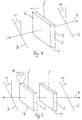
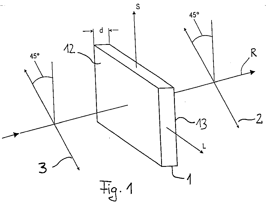
- Figure 1 shows an interference filter according to the invention, which consists of a Arrangement of a birefringent element 1 and two linear polarizers 2 and 3.
- the birefringent element 1 consists of a mercury halide single crystal and has a thickness d of a few Millimeters.
- the birefringent crystal is cut so that the of slower and faster axis L or F spanned plane parallel to The front or back surface of the crystal runs with the beam direction R perpendicular to it.
- the forward direction of 45 ° is rotated with respect to the axes of the birefringent element 1 first a defined polarization state of the light any Wavelengths produced, the 45 ° position of the polarizer causes that the parallel to the fast axis of the birefringent element polarized component has the same amplitude as that parallel to polarized slow axis.
- the initial phase difference between these polarization components before entering the birefringent element is independent of the wavelength for everyone spectral components zero.
- the birefringent element takes Now, depending on the wavelength, polarization coding of the spectral Components before by making a wavelength dependent phase difference ⁇ ( ⁇ ) between the individual polarization components induced.
- the spectral filtering of the polarization-coded light takes place on Exit of the birefringent element with the help of another Polarizer 2, which is also a linear polarizer here and its Forward direction parallel to the forward direction of the input polarizer 3 is.
- the spectral filtering is theoretically considered Pancharatnam's phase.
- Figure 2 shows an interference filter, which compared to the arrangement Figure 1 is extended by an electro-optical delay element 4.
- the other arrangement of components birefringent plate 1 ', Output polarizer 2 'and input polarizer 3' corresponds to that Design of the interference filter from FIG. 1.
- the electro-optical retardation element 4 is used for continuous Tuning the comb-like pass band of the interference filter.
- the retardation element 4 consists of a material whose Birefringence can be changed electrically. this happens in particular in that a voltage is applied to the delay element 4 is applied, which is indicated here by a voltage source 14.
- the retardation element 4 is oriented so that its rapid or slow axis S or L parallel to the axes of the birefringent Elements 1 'runs. Particularly suitable for continuous Fast liquid crystal cells, Kerr cells and Pockels cells and cells with other electro-optical materials.
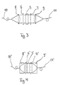
- Figures 3 and 4 show the arrangement of an inventive Interference filter in the application between two glass fibers 10 and 11 or 10 'and 11'.
- the crystal optical interference filter consists of both Figures from a birefringent plate 5 and 5 ', and one each polarizer 6, 6 ', 7, 7' arranged in front or behind.
- the polarizers are, for example, relative, as shown in Figures 1 and 2 oriented to each other and to the axes of the birefringent plate.
- a given spectral light emerges from the ends of the glass fibers 10, 10 ' Composition expanding conically. It is by means of a first lens 8 or 8 'converted into preferably plane waves, wherein then parallel light emerges from the lens. That’s why Fiber end in the area of the focal point of the lens 8 or 8 '.
- the light coupled out on the fiber 10 passes through the interference filter as parallel beam and strikes another at the filter output Lens 9 or 9 ', with which the light returns into the outgoing fiber 11 or 11 'is coupled.
- the end of the fiber 11 or 11 ' is in Area of focus of the lens 9 or 9 '.
- the lenses 8 and 9 from FIG. 3 are infrared-compatible lenses, the lenses 8 'and 9' of Figure 4 are gradient index lenses.
Landscapes
- Physics & Mathematics (AREA)
- General Physics & Mathematics (AREA)
- Optics & Photonics (AREA)
- Nonlinear Science (AREA)
- Polarising Elements (AREA)
- Crystals, And After-Treatments Of Crystals (AREA)
- Lasers (AREA)
- Spectrometry And Color Measurement (AREA)
- Inorganic Compounds Of Heavy Metals (AREA)
- Optical Filters (AREA)
- Investigating Or Analysing Materials By Optical Means (AREA)
Abstract
Die Erfindung betrifft ein kristalloptisches Interferenzfilter mit
periodischem Durchlaßbereich, insbesondere für den Wellenlängenmultiplexbetrieb
von optischen Netzen in der Telekommunikation, sowie ein
Verfahren zur aktiven Anpassung des spektralen Durchlaßbereichs eines
derartigen Interferenzfilters. Das Interferenzfilter besteht wenigstens aus
einem doppelbrechenden Element (1, 1', 5, 5') sowie einem an dessen
Ausgang angeordneten Polarisator (2, 2', 7, 7') wobei das doppelbrechende
Element einen Quecksilber(I)halogenid-Einkristall (Hg2Cl2, Hg2Br2, Hg2J2)
ist. Trifft auf das doppelbrechende Element Licht beliebiger spektraler
Zusammensetzung, jedoch in einem definierten Polarisationszustand, so
werden durch das doppelbrechende Element die einzelnen spektralen
Komponenten mit einer definierten Polarisation kodiert und können dann
wellenlängenabhängig mit Hilfe des Ausgangspolarisators (2, 2', 7, 7')
herausgefiltert werden. Das Interferenzfilter weist eine periodische
Durchlaßcharakteristik auf. Mit Hilfe weiterer in den Strahlengang
eingebrachter elektrooptischer Verzögerungselemente (4) gelingt ein
kontinuierliches Durchstimmen der Durchlaßcharakteristik.
Kanalabstände im Bereich von einem Nanometer können bei der
Verwendung von Quecksilber(I)halogenid-Einkristallen bereits mit
doppelbrechenden Platten einer Stärke von wenigen Millimetern realisiert
werden.
Description
Die Erfindung betrifft ein kristalloptisches Interferenzfilter mit periodischem Durchlaßbereich, insbesondere für den Wellenlängenmultiplexbetrieb von optischen Netzen in der Telekommunikation, sowie ein Verfahren zur aktiven Anpassung des spektralen Durchlaßbereichs eines derartigen Interferenzfilters.The invention relates to a crystal optical interference filter periodic pass band, especially for wavelength division multiplexing of optical networks in telecommunications, as well as a Method for actively adjusting the spectral pass band of a such interference filter.
Zur Erhöhung der Übertragungskapazität von optischen Nachrichtenübertragungssystemen ist die Einführung des sogenannten WDM (wavelength division multiplex) -Betriebs geplant. Dabei erfolgt die Übertragung nicht nur auf einem spektralen Kanal, sondern parallel auf mehreren Kanälen, von denen jeder einzelne Licht einer eigenen individuellen Wellenlänge überträgt. Die einzelnen Kanäle liegen im allgemeinen in etwa gleichem spektralen Abstand nebeneinander. Dieser Abstand beträgt z. B. ein Nanometer, kann aber im Prinzip noch viel kleiner sein. Da die Verstärkung dieses spektralen Kamms im dritten optischen Fenster bei 1550 nm besonders ökonomisch mit optischen Verstärkern erfolgen kann, ist dieser Wellenlängenbereich für den WDM-Betrieb besonders interessant.To increase the transmission capacity of optical communication systems is the introduction of the so-called WDM (wavelength division multiplex) operation planned. The Transmission not only on a spectral channel, but in parallel multiple channels, each with its own light individual wavelength transmits. The individual channels are in the generally at approximately the same spectral distance next to each other. This Distance is z. B. a nanometer, but can in principle be much smaller be. Because the amplification of this spectral comb in the third optical Windows at 1550 nm particularly economical with optical amplifiers this wavelength range is for WDM operation especially interesting.
Optische spektrale Filter mit einem kammartigen Durchlaßbereich, der an die Übertragungskanäle angepaßt ist, erlauben die Regeneration der spektralen Reinheit im WDM-Betrieb. Das passive Filter unterdrückt Licht, das zwischen den spektralen Kanälen auftritt, z. B. durch die spontane Emission im optischen Verstärker, durch Brillouin- oder Ramanstreuung oder durch anderes Fremdlicht, und erhöht somit das Signal-Rauschverhältnis bei der Detektion.Optical spectral filter with a comb-like pass band, the the transmission channels are adapted, allow the regeneration of the spectral purity in WDM operation. The passive filter suppresses light, that occurs between the spectral channels, e.g. B. by the spontaneous Emission in the optical amplifier, through Brillouin or Raman scattering or by other extraneous light, and thus increases the signal-to-noise ratio in detection.
Bei der aktive Abstimmung solcher Filter wird im allgemeinen der kammartige Durchlaßbereich auf der Wellenlängenskala parallel verschoben. Solche abstimmbaren Filter erlauben das Zu- oder Abschalten weiterer Systeme von parallelen spektralen Kanälen oder das präzise Nachjustieren des Wellenlängenkamms.When actively tuning such filters, the comb-like pass band on the wavelength scale parallel postponed. Such tunable filters allow switching on or off other systems of parallel spectral channels or that precise Readjust the wavelength comb.
Interferenzfilter mit periodischem kammartigem Durchlaßbereich sind seit langem bekannt. Man unterscheidet solche mit Vielstrahlinterferenz wie das Interferenzgitter oder das Fabry-Perot Filter und solche mit Zweistrahlinterferenz wie das Michelson- und das Mach-Zehnder Interferometer. Bei der Vielstrahlinterferenz wird der Durchlaßbereich durch periodische schmale Transmissionslinien gekennzeichnet, zwischen denen breite undurchlässige Bereiche liegen. Bei der Zweistrahlinterferenz ist die Transmissionscharakteristik eine Sinusquadratverteilung mit gleich breiten Transmissions- und Absorptionsbereichen.Interference filters with a periodic comb-like pass band have been known for a long time. A distinction is made between those with multibeam interference such as the interference grating or the Fabry-Perot filter and those with Two-beam interference like the Michelson and Mach Zehnder Interferometer. In the case of multi-beam interference, the pass band characterized by periodic narrow transmission lines, between where there are wide impermeable areas. With two-beam interference the transmission characteristic is a sine square distribution with the same wide transmission and absorption ranges.
Unter den Zweistrahlinterferenzfiltern gibt es eine besondere Klasse, die mechanisch sehr stabil ist, dafür aber nicht ohne weiteres abgestimmt werden kann. Das sind die kristalloptischen Interferenzfilter mit periodischem Durchlaßbereich, wie das Lyotfilterelement, das Solcfilter und ähnliche Anordnungen. Bei diesen Filtern sind die interferierenden Lichtstrahlen die schnelle und langsame Eigenwelle in einem doppelbrechenden Kristall. Diese Filter sind mechanisch so stabil wie der Kristall. Da die Länge der Interferometerarme aber eindeutig durch die Dicke d der Kristallplatte festgelegt wird, besteht keine kontinuierliche Abstimmungsmöglichkeit, außer durch Temperaturänderungen. Das Umschalten von den Transmissionsbereichen auf die Absorptionsbereiche und umgekehrt, d. h. die Verschiebung des Filters um eine halbe Periode (reziproker Durchlaßbereich), ist durch Veränderung der Eingangspolarisation immer möglich.There is a special class among the two-beam interference filters, the mechanically very stable, but not easily matched can be. These are the crystal optical interference filters with periodic passband, such as the Lyot filter element, the Solc filter and similar arrangements. These filters are the interfering ones Beams of light the fast and slow natural wave in a birefringent Crystal. These filters are mechanically as stable as the crystal. Since the length of the interferometer arms is clearly determined by the thickness d of the Crystal plate is determined, there is no continuous coordination, except through temperature changes. Switching from the transmission areas to the absorption areas and vice versa, d. H. the shift of the filter by half a period (reciprocal Pass band), is always by changing the input polarization possible.
Der Abstand der Kanäle ist bei kristalloptischen Interferenzfiltern aus doppelbrechendem Material durch die Differenz der Brechungsindizes der schnellen bzw. langsamen Achse des Kristalls, sowie durch dessen Dicke d festgelegt. Man kann zeigen, daß bei dem bekanntesten doppelbrechenden Material Kalkspat ein etwa 14 mm dicker Kristall notwendig ist, um den für den WDM-Betrieb von optischen Netzen geforderten Kanalabstand von mindestens einem Nanometer zu realisieren. Die Gewinnung derartig großer Kalkspatkristalle ist jedoch sehr kostspielig, so daß diese Filter nur für seltene Sonderzwecke eingesetzt werden können.The distance between the channels is off with crystal-optical interference filters birefringent material by the difference in the refractive indices of the fast or slow axis of the crystal, and by its thickness d fixed. It can be shown that the most famous birefringent Material of calcite is an approximately 14 mm thick crystal is necessary for the the channel spacing required by WDM operation of optical networks to realize at least one nanometer. The extraction of such Large calcite crystals are very expensive, so these filters only can be used for rare special purposes.
Der Erfindung liegt deshalb die Aufgabe zugrunde, ein kristalloptisches Interferenzfilter zur Verfügung zu stellen, welches kostengünstig ist und die Anpassung des spektralen Durchlaßbereichs des Filters an die Anforderungen des optischen WDM-Netzes erlaubt. Weiterhin soll ein Verfahren zur aktiven Abstimmung des Interferenzfilters zur Verfügung gestellt werden. The invention is therefore based on the object of a crystal optical To provide interference filter, which is inexpensive and the adaptation of the spectral pass band of the filter to the WDM optical network requirements allowed. Furthermore, a Methods for actively tuning the interference filter are available be put.
Die Lösung der Aufgabe besteht erfindungsgemäß bei einem kristalloptischen Interferenzfilter mit periodischem Durchlaßbereich, insbesondere für den Wellenlängenmultiplexbetrieb von optischen Netzen in der Telekommunikation, wenigstens bestehend aus einem doppelbrechenden Element sowie einem an dessen Ausgang angeordneten Polarisator, wobei das doppelbrechende Element ein Quecksilber(I)halogenid-Einkristall ist.According to the invention, the object is achieved with a crystal-optical one Interference filter with a periodic pass band, in particular for wavelength division multiplexing of optical networks in the Telecommunications, at least consisting of a birefringent Element and a polarizer arranged at its output, wherein the birefringent element is a mercury (I) halide single crystal.
Quecksilberhalogenide sind im Infraroten, d.h. auch im Wellenlängenbereich um 1500 Nanometer, der für den WDM-Betrieb von optischen Netzen genutzt wird, transparent und weisen in diesem Bereich eine hohe Doppelbrechung auf. Der Unterschied der Brechungsindizes der schnellen und langsamen Achse ist mit Werten von bis zu Δn = 1 etwa fünfmal größer als bei Kalkspat. Eine saubere Trennung der etwa 1 nm beabstandeten WDM-Kanäle läßt sich daher bereits mit Quecksilberhalogenidkristallen von 2 bis 5 mm Dicke erreichen. Die Verwendung von Quecksilber(I)halogeniden (Hg2Cl2, Hg2Br2, Hg2J2) als kristalloptische Interferenzfilter mit periodischem Durchlaßbereich, insbesondere für den Wellenlängenmultiplexbetrieb von optischen Netzen in der Telekommunikation, ist daher vorteilhaft.Mercury halides are transparent in the infrared, ie also in the wavelength range around 1500 nanometers, which is used for the WDM operation of optical networks, and have a high birefringence in this range. The difference in the refractive indices of the fast and slow axes is around five times greater than that of calcite with values of up to Δn = 1. A clean separation of the WDM channels spaced about 1 nm can therefore already be achieved with mercury halide crystals of 2 to 5 mm in thickness. The use of mercury (I) halides (Hg 2 Cl 2 , Hg 2 Br 2 , Hg 2 J 2 ) as a crystal-optical interference filter with a periodic pass band, in particular for the wavelength division multiplex operation of optical networks in telecommunications, is therefore advantageous.
Die drei Quecksilberhalogenide Hg2J2, Hg2Cl2 und Hg2Br2 lassen sich aus der Dampfphase in guter Qualität als große Kristalle züchten. Die Kristalle lassen sich spalten, sägen und polieren. Säge- und Polituroberflächen können durch Tempern unterhalb der Sublimationstemperatur von uneinheitlichen Oberflächenschichten gereinigt und/oder rekristallisiert werden. Somit können Einflüsse, die die Doppelbrechung beeinträchtigen eliminiert werden.The three mercury halides Hg 2 J 2 , Hg 2 Cl 2 and Hg 2 Br 2 can be grown in good quality as large crystals from the vapor phase. The crystals can be split, sawn and polished. Sawing and polishing surfaces can be cleaned from inconsistent surface layers and / or recrystallized by tempering below the sublimation temperature. In this way, influences that impair birefringence can be eliminated.
Vorzugsweise wird als doppelbrechendes Element ein Quecksilberiodid-Einkristall Hg2J2 verwendet, da dieser im Infraroten die größte Doppelbrechung aufweist.A mercury iodide single crystal Hg 2 J 2 is preferably used as the birefringent element, since this has the greatest birefringence in the infrared.
Durch das doppelbrechende Element wird das eingestrahlte Licht abhängig von dessen Wellenlänge und Anfangspolarisation in einen bestimmten Polarisationszustand gebracht (Polarisationskodierung der spektralen Komponenten).The incident light is dependent on the birefringent element from its wavelength and initial polarization into a certain one Brought polarization state (polarization coding of the spectral Components).
Damit die parallel zur langsamen bzw. schnellen Achse des doppelbrechenden Kristalls polarisierten Komponenten des eingestrahlten Lichts räumlich nicht auseinanderlaufen, wird der Quecksilberhalogenid-Kristall so geschnitten und in den Strahlengang eingebracht, daß die aus langsamer und schneller Achse aufgespannte Ebene parallel zur Front- bzw. Rückfläche des Kristalls und senkrecht zur Strahlrichtung orientiert ist. Somit findet lediglich eine Polarisationsveränderung des einlaufenden Lichts statt, während das räumliche Profil unverändert bleibt.So that the parallel to the slow or fast axis of the birefringent crystal polarized components of the irradiated The light does not diverge spatially, the mercury halide crystal cut and placed in the beam path so that the slower and faster axis spanned plane parallel to the front or Back surface of the crystal and oriented perpendicular to the beam direction is. Thus there is only a change in polarization of the incoming Light takes place while the spatial profile remains unchanged.
Wesentlicher Bestandteil des kristalloptischen Interferenzfilters ist neben dem doppelbrechenden Element ein dahinter angeordneter Polarisator, insbesondere Linearpolarisator, welcher dazu dient, die unerwünschten spektralen Komponenten, die durch das doppelbrechende Element mit einem bestimmten Polarisationszustand kodiert wurden, herauszufiltern oder zu reflektieren. Nur diejenigen spektralen Komponenten, deren Polarisation mit der Durchlaßrichtung des Ausgangspolarisators übereinstimmt, werden vom Filter transmittiert. Auf diese Weise wird die spektrale Filterung des optischen Signals erreicht. Der Polarisator ist so in den Strahlengang eingebracht, daß die Polarisations-richtung, die er transmittiert, in der durch langsame und schnelle Achse des doppelbrechenden Elements aufgespannten Ebene liegt.An essential part of the crystal optical interference filter is besides a polarizer arranged behind the birefringent element, in particular linear polarizer, which serves to avoid the unwanted spectral components by using the birefringent element a certain polarization state were coded out or reflect. Only those spectral components whose Polarization with the transmission direction of the output polarizer matches, are transmitted by the filter. In this way the spectral filtering of the optical signal achieved. The polarizer is so in introduced the beam path that the polarization direction that he transmitted in the slow and fast axis of the birefringent element spanned plane.
Damit das doppelbrechende Element die verschiedenen spektralen Komponenten der einlaufenden Welle mit verschiedenen Polarisationen kodieren kann, ist es notwendig, daß das Licht dem doppelbrechenden Element in einem definierten Polarisationszustand zugeführt wird. Dies kann zum einen durch aktives Polarisationsmanagement im optischen Netz realisiert werden, indem z.B. nur bestimmte Polarisationen über die Glasfasern übertragen werden. Vorteilhaft ist darüber hinaus eine Ausgestaltung des kristalloptischen Interferenzfilters, bei welcher vor dem doppelbrechendem Element ein weiterer Polarisator angeordnet ist, da somit das Interferenzfilter unabhängig von den Übertragungseigenschaften des optischen Netzes ist.So that the birefringent element the different spectral Components of the incoming wave with different polarizations can encode, it is necessary that the light is birefringent Element is supplied in a defined polarization state. This can, on the one hand, through active polarization management in the optical network can be realized by e.g. only certain polarizations over the Glass fibers are transferred. One is also advantageous Design of the crystal optical interference filter, in which before birefringent element another polarizer is arranged because thus the interference filter regardless of the transmission properties of the optical network.
Dieser Polarisator ist vorzugsweise ein Linearpolarisator, dessen Durchlaßrichtung um etwa 45° gegenüber der langsamen bzw. schnellen Achse des doppelbrechenden Kristalls versetzt ist. Diese Anordnung maximiert die Wirkungen der Doppelbrechung.This polarizer is preferably a linear polarizer whose transmission direction by about 45 ° compared to the slow or fast axis of the birefringent crystal is offset. This arrangement maximizes the Effects of birefringence.
Entsprechend ist es vorteilhaft, wenn die Durchlaßrichtung des Polarisators am Ausgang des doppelbrechenden Elements ebenfalls um etwa 45° gegenüber der langsamen bzw. schnellen Achse des doppelbrechenden Kristalls versetzt ist. Die Durchlaßrichtungen von Ein- und Ausgangspolarisatoren sind damit vorzugsweise parallel oder senkrecht zueinander undliegen in parallelen Ebenen. Das Umschalten vom normalen auf den reziproken Durchlaßbereich des Interferenzfilters gelingt in diesem Fall sehr einfach durch Drehen des Ein- oder Ausgangspolarisators um 90°.Accordingly, it is advantageous if the forward direction of the polarizer at the exit of the birefringent element also around 45 ° opposite the slow or fast axis of the birefringent Crystal is offset. The pass directions of input and output polarizers are therefore preferably parallel or perpendicular to each other and lie in parallel planes. Switching from normal to reciprocal pass band of the interference filter succeeds in this case very simply by turning the input or output polarizer by 90 °.
Die kontinuierliche Durchstimmung des spektralen Durchlaßbereichs des Interferenzfilters wird vorteilhaft durch ein elektrooptisches Retardierungselement erreicht, welches am Eingang des doppelbrechenden Elements ggf. zwischen dem Kristall und dem Eingangspolarisator in den Strahlengang eingebracht ist. Durch das elektrooptische Retardierungselement kann die gesamte effektive Doppelbrechung des Interferenzfilters aktiv verändert werden, wodurch auch die Polarisationskodierung der einzelnen spektralen Komponenten variiert wird. Die Polarisationskodierung wird somit durch ein elektrisches Signal, welches die Doppelbrechung des Retardierungselements verändert, gesteuert.The continuous tuning of the spectral pass band of the Interference filter is advantageous due to an electro-optical retardation element reached, which may be at the entrance of the birefringent element between the crystal and the input polarizer in the beam path is introduced. Due to the electro-optical retardation element total effective birefringence of the interference filter actively changed be, which also the polarization coding of the individual spectral Components is varied. The polarization coding is thus by an electrical signal indicating the birefringence of the retardation element changed, controlled.
Das elektrooptische Retardierungselement ist vorzugsweise eine schnelle Flüssigkristallzelle, eine Kerr- oder eine Pockelzelle oder eine Zelle aus einem anderen elektrooptischen Material.The electro-optical retardation element is preferably a fast one Liquid crystal cell, a Kerr or a Pockelzell or a cell another electro-optical material.
Weiterhin kann zur kontinuierlichen Durchstimmung des spektralen Durchlaßbereichs des Interferenzfilters zwischen dem doppelbrechenden Element und dem Ausgangspolarisator eine λ/4-Retardierungsplatte angeordnet sein. Die Ausrichtung der Achsen der λ/4-Retardierungsplatte ist um 45° relativ zu den Achsen des doppelbrechenden Elements versetzt. Die aktive Abstimmung erfolgt durch Anpassung der Durchlaßrichtung des Ausgangspolarisators.Furthermore, the continuous tuning of the spectral Passband of the interference filter between the birefringent Element and the output polarizer a λ / 4 retardation plate be arranged. The alignment of the axes of the λ / 4 retardation plate is offset by 45 ° relative to the axes of the birefringent element. The active tuning is done by adjusting the forward direction of the Output polarizer.
Zum Einbau des Interferenzfilters in ein optisches Netz ist vorgesehen, daß das Interferenzfilter mit zwei Linsen zwischen zwei optischen Faserenden eingefügt ist. Dabei wird das aus der Faser ausgetretene Licht mittels der ersten Linse vorzugsweise in ebene Wellen umgewandelt und dem Interferenzfilter zugeführt. Am Filterausgang wird es mittels der zweiten Linse wieder in die Phase eingekoppelt. Die Linsen sind Objektive oder Gradientenindexlinsen. To install the interference filter in an optical network, it is provided that the interference filter with two lenses between two optical fiber ends is inserted. Here, the light emerging from the fiber is by means of the first lens preferably converted into plane waves and the Interference filter supplied. At the filter outlet it becomes by means of the second one Lens coupled back into the phase. The lenses are lenses or Gradient index lenses.
Zur Verminderung von Reflexionen an Grenzflächen, insbesondere am Übergang Luft/Glas ist eine Brechungsindexanpassung mittels Ölen mit geeignete Brechungsindizes vorgesehen. Die einzelnen Bauteile bzw. Komponenten des Interferenzfilters, d.h. Polarisatoren, doppelbrechender Kristall und ggf. weitere Verzögerungselemente, werden dabei in definiertem Abstand voneinander angeordnet und die Zwischenräume zwischen den Bauteilen mit Öl gefüllt. Zur Herstellung von Ölspalten definierter Dicke werden vorzugsweise Abstandshalter zwischen den einzelnen Bauteilen verwendet.To reduce reflections at interfaces, especially on Air / glass transition is a refractive index adjustment using oils with suitable refractive indices are provided. The individual components or Components of the interference filter, i.e. Polarizers, birefringent Crystal and possibly other delay elements are in defined distance from each other and the spaces filled with oil between the components. For the production of oil gaps defined thickness are preferably spacers between the individual components used.
Kurzbeschreibung der Zeichnung wobei zeigen:
- Figur 1
- ein Interferenzfilter bestehend aus einer doppelbrechenden Platte und jeweils einem Ein- und Ausgangspolarisator
Figur 2- ein Interferenzfilter bestehend aus einer doppelbrechenden Platte, zwei Polarisatoren sowie einer elektrooptischen Verzögerungsplatte
Figuren 3 und 4- den Einbau eines erfindungsgemäßen Interferenzfilters zwischen zwei Faserenden
- Figure 1
- an interference filter consisting of a birefringent plate and one input and one output polarizer
- Figure 2
- an interference filter consisting of a birefringent plate, two polarizers and an electro-optical delay plate
- Figures 3 and 4
- the installation of an interference filter according to the invention between two fiber ends
Figur 1 zeigt ein erfindungsgemäßes Interferenzfilter, welches aus einer
Anordnung aus einem doppelbrechenden Element 1 sowie zwei Linearpolarisatoren
2 und 3 besteht. Das doppelbrechende Element 1 besteht aus
einem Quecksilberhalogenid-Einkristall und hat eine Dicke d von einigen
Millimetern. Der doppelbrechende Kristall ist so geschnitten, daß die von
langsamer und schneller Achse L bzw. F aufgespannte Ebene parallel zur
Front- bzw. Rückfläche des Kristalls verläuft, wobei die Strahlrichtung R
senkrecht dazu ist.Figure 1 shows an interference filter according to the invention, which consists of a
Arrangement of a birefringent element 1 and two
Der doppelbrechende Kristall weist für entlang der S- bzw. L-Achse
polarisiertes Licht, verschiedene Brechungsindizes nL bzw. nS mit einem
Brechungsindexunterschied
Mit Hilfe des Eingangspolarisators 3, dessen Durchlaßrichtung um 45°
gegenüber den Achsen des doppelbrechenden Elements 1 gedreht ist, wird
zunächst ein definierter Polarisationszustand des Lichts beliebiger
Wellenlängen hergestellt, wobei die 45°-Stellung des Polarisators bewirkt,
daß die parallel zur schnellen Achse des doppelbrechenden Elements
polarisierte Komponente die gleiche Amplitude hat wie die parallel zur
langsamen Achse polarisierte. Der anfängliche Phasenunterschied
zwischen diesen Polarisationskomponenten vor dem Eintritt in das
doppelbrechende Element ist unabhängig von der Wellenlänge für alle
spektralen Komponenten gleich Null. Das doppelbrechende Element nimmt
nun wellenlängenabhängig eine Polarisationskodierung der spektralen
Komponenten vor, indem es einen wellenlängenabhängigen Phasenunterschied
Δϕ(λ) zwischen den einzelnen Polarisationskomponenten
induziert.With the help of the
Die spektrale Filterung des polarisationskodierten Lichts erfolgt am
Ausgang des doppelbrechenden Elements mit Hilfe eines weiteren
Polarisators 2, der hier ebenfalls ein Linearpolarisator ist und dessen
Durchlaßrichtung parallel zur Durchlaßrichtung des Eingangspolarisators
3 ist. Der spektralen Filterung liegen theoretisch die Überlegungen zu
Pancharatnams Phase zugrunde.The spectral filtering of the polarization-coded light takes place on
Exit of the birefringent element with the help of another
In der hier dargestellten Anordnung wird demnach nur Licht mit einem
Phasenunterschied von Δϕ=0 bzw.
Die Anpassung der spektralen Durchlaßcharakteristik an veränderte
Anforderungen im optischen Netz geschieht bei dem hier dargestellten
Interferenzfilter durch Verdrehen der Polarisatoren 2 bzw. 3. Das
Umschalten auf reziproken Durchlaßbereich, d.h. Transmission aller zuvor
komplett unterdrückten Wellenlängen und umgekehrt, wird durch
Verdrehen des Polarisators 2 bzw. 3 um 90° erreicht.The adaptation of the spectral transmission characteristics to changed
Requirements in the optical network happen with the one shown here
Interference filter by turning the
Figur 2 zeigt ein Interferenzfilter, welches gegenüber der Anordnung aus Figur 1 um ein elektrooptisches Verzögerungselement 4 erweitert ist. Die sonstige Anordnung der Komponenten doppelbrechende Platte 1', Ausgangspolarisator 2' und Eingangspolarisator 3' entspricht der Gestaltung des Interferenzfilters aus Figur 1.Figure 2 shows an interference filter, which compared to the arrangement Figure 1 is extended by an electro-optical delay element 4. The other arrangement of components birefringent plate 1 ', Output polarizer 2 'and input polarizer 3' corresponds to that Design of the interference filter from FIG. 1.
Das elektrooptische Retardierungselement 4 dient zum kontinuierlichen
Durchstimmen des kammartigen Durchlaßbereichs des Interferenzfilters.
Das Retardierungselement 4 besteht aus einem Material, dessen
Doppelbrechung sich auf elektrischem Wege verändern läßt. Dies geschieht
insbesondere dadurch, daß an das Verzögerungselement 4 eine Spannung
angelegt wird, welches hier durch eine Spannungsquelle 14 angedeutet ist.
Das Retardierungselement 4 ist so ausgerichtet, daß seine schnelle bzw.
langsame Achse S bzw. L parallel zu den Achsen des doppelbrechenden
Elements 1' verläuft. Besonders geeignet zum kontinuierlichen
Durchstimmen sind schnelle Flüssigkristallzellen, Kerrzellen und
Pockelszellen und Zellen mit anderen elektrooptischen Materialien.The electro-optical retardation element 4 is used for continuous
Tuning the comb-like pass band of the interference filter.
The retardation element 4 consists of a material whose
Birefringence can be changed electrically. this happens
in particular in that a voltage is applied to the delay element 4
is applied, which is indicated here by a
Die Figuren 3 und 4 zeigen die Anordnung eines erfindungsgemäßen
Interferenzfilters im Anwendungsfall zwischen zwei Glasfasern 10 und 11
bzw. 10' und 11'. Das kristalloptische Interferenzfilter besteht in beiden
Figuren aus einer doppelbrechenden Platte 5 bzw. 5', sowie jeweils einem
davor bzw. dahinter angeordneten Polarisator 6, 6', 7, 7'. Die Polarisatoren
sind beispielsweise so, wie in den Figuren 1 und 2 dargestellt relativ
zueinander und zu den Achsen der doppelbrechenden Platte orientiert.Figures 3 and 4 show the arrangement of an inventive
Interference filter in the application between two
Aus den Enden der Glasfasern 10, 10' tritt Licht einer gegebenen spektralen
Zusammensetzung sich kegelförmig aufweitend aus. Es wird mittels einer
ersten Linse 8 bzw. 8' in vorzugsweise ebene Wellen umgewandelt, wobei
dann aus der Linse paralleles Licht austritt. Dazu befindet sich das
Faserende im Bereich des Brennpunktes der Linse 8 bzw. 8'.A given spectral light emerges from the ends of the
Das auf der Faser 10 ausgekoppelte Licht durchläuft das Interferenzfilter als
paralleles Strahlenbündel und trifft am Filterausgang auf eine weitere
Linse 9 bzw. 9', mit welcher das Licht wieder in die abgehende Faser 11 bzw.
11' eingekoppelt wird. Dazu befindet sich das Ende der Faser 11 bzw. 11' im
Bereich des Brennpunktes der Linse 9 bzw. 9'.The light coupled out on the
Die Linsen 8 und 9 aus Figur 3 sind infrarottaugliche Objektive, die Linsen
8' und 9' aus Figur 4 sind Gradientenindexlinsen. The
- 1,1', 5,5'1.1 ', 5.5'
- doppelbrechendes Element (Quecksilber(I)halogenid-Einkristall)birefringent element (mercury (I) halide single crystal)
- 2,2', 7,7'2.2 ', 7.7'
- AusgangspolarisatorOutput polarizer
- 3,3', 6,6'3.3 ', 6.6'
- EingangspolarisatorInput polarizer
- 44th
- elektrooptisches Retardierungselementelectro-optical retardation element
- 8,8', 9,9'8.8 ', 9.9'
- Linselens
- 10,10', 11,11'10.10 ', 11.11'
- Faserfiber
- 12,1312.13
- Front- bzw. Rückfläche des doppelbrechenden ElementsFront or back surface of the birefringent element
- 1414
- SpannungsquelleVoltage source
- F/LF / L
- schnelle/langsame Achsefast / slow axis
- RR
- StrahlrichtungBeam direction
Claims (16)
daß der doppelbrechende Quecksilber(I)halogenid-Einkristall so geschnitten ist, daß die von langsamer und schneller Achse (L bzw. F) aufgespannte Ebene parallel zur Front- bzw. Rückfläche (12 bzw. 13) des Kristalls verläuft, wobei die Strahlrichtung (R) senkrecht dazu ist.Interference filter according to claim 1, characterized in
that the birefringent mercury (I) halide single crystal is cut so that the plane spanned by the slow and fast axes (L or F) runs parallel to the front or back surface (12 or 13) of the crystal, the beam direction ( R) is perpendicular to it.
daß vor dem doppelbrechenden Element (1, 1', 5, 5') ein weiterer Polarisator (3, 3', 6, 6') angeordnet ist.Interference filter according to claim 1 or 2, characterized in
that a further polarizer (3, 3 ', 6, 6') is arranged in front of the birefringent element (1, 1 ', 5, 5').
daß die Durchlaßrichtung des Polarisators (3, 3', 6, 6') am Eingang des doppelbrechenden Elements (1, 1', 5, 5') um etwa 45° gegenüber der langsamen bzw. schnellen Achse des doppelbrechenden Kristalls versetzt ist.Interference filter according to claim 3, characterized in
that the forward direction of the polarizer (3, 3 ', 6, 6') at the entrance of the birefringent element (1, 1 ', 5, 5') is offset by approximately 45 ° with respect to the slow or fast axis of the birefringent crystal.
daß die Durchlaßrichtung des Polarisators (2, 2', 7, 7') am Ausgang des doppelbrechenden Elements (1, 1', 5, 5') um etwa 45° gegenüber der langsamen bzw. schnellen Achse des doppelbrechenden Kristalls versetzt ist.Interference filter according to one of the preceding claims, characterized in that
that the forward direction of the polarizer (2, 2 ', 7, 7') at the output of the birefringent element (1, 1 ', 5, 5') is offset by approximately 45 ° with respect to the slow or fast axis of the birefringent crystal.
daß zur kontinuierlichen Durchstimmung des spektralen Durchlaßbereichs am Eingang bzw. Ausgang des doppelbrechenden Elements ein elektrooptisches Retardierungselement (4) in den Strahlengang eingebracht ist, wobei dieses gegebenenfalls zwischen dem doppelbrechenden Element und dem Eingangs- (3, 3', 6, 6') bzw. Ausgangspolarisator (2, 2', 7, 7') angeordnet ist.Interference filter according to one of the preceding claims, characterized in that
that for the continuous tuning of the spectral pass band at the input or output of the birefringent element, an electro-optical retardation element (4) is introduced into the beam path, this possibly between the birefringent element and the input (3, 3 ', 6, 6') or Output polarizer (2, 2 ', 7, 7') is arranged.
daß das elektrooptische Retardierungselement (4) eine schnelle Flüssigkristallzelle ist.Interference filter according to claim 6, characterized in
that the electro-optical retardation element (4) is a fast liquid crystal cell.
daß das elektrooptische Retardierungselement (4) eine Kerr- oder Pockelszelle ist.Interference filter according to claim 6, characterized in
that the electro-optical retardation element (4) is a Kerr or Pockels cell.
daß zur kontinuierlichen Durchstimmung des spektralen Durchlaßbereichs des Interferenzfilters zwischen dem doppelbrechenden Element (1, 1', 5, 5') und dem Ausgangspolarisator (2, 2', 7, 7') eine λ/4-Retardierungsplatte unter 45° relativ zur schnellen bzw. langsamen Achse des doppelbrechenden Elements (1, 1', 5, 5') eingefügt ist, wobei die Abstimmung durch Anpassung der Durchlaßrichtung des Ausgangspolarisator (2, 2', 7, 7') erfolgt.Interference filter according to one of the preceding claims, characterized in that
that for continuous tuning of the spectral passband of the interference filter between the birefringent element (1, 1 ', 5, 5') and the output polarizer (2, 2 ', 7, 7') a λ / 4 retardation plate at 45 ° relative to the fast or slow axis of the birefringent element (1, 1 ', 5, 5') is inserted, the tuning being carried out by adjusting the forward direction of the output polarizer (2, 2 ', 7, 7').
daß es zur Ankopplung an das optische Netz mit zwei Linsen (8, 8', 9, 9') zwischen zwei optische Faserenden (10, 10', 11, 11') eingefügt ist, wobei das aus der Faser (10, 10') austretende Licht mittels der ersten Linse (8, 8') vorzugsweise in ebene Wellen umgewandelt und am Interferenzfilterausgang mittels der zweiten Linse (9, 9') in die Faser (11, 11') eingekoppelt wird.Interference filter according to one of the preceding claims, characterized in that
that it is inserted for coupling to the optical network with two lenses (8, 8 ', 9, 9') between two optical fiber ends (10, 10 ', 11, 11'), the fiber (10, 10 ' ) emerging light is preferably converted into plane waves by means of the first lens (8, 8 ') and is coupled into the fiber (11, 11') at the interference filter output by means of the second lens (9, 9 ').
daß die Linsen Objektive (8, 9) oder Gradientenindexlinsen (8', 9,) sind.Interference filter according to claim 10, characterized in
that the lenses are lenses (8, 9) or gradient index lenses (8 ', 9,).
daß die einzelnen Bauteile in definiertem Abstand voneinander angeordnet sind, wobei in die Zwischenräume zur Verminderung von Reflexionen an den Grenzflächen Öle geeigneter Brechungsindizes eingebracht sind.Interference filter according to claim 10 or 11, characterized in that
that the individual components are arranged at a defined distance from one another, oils having suitable refractive indices being introduced into the interspaces to reduce reflections at the interfaces.
daß Abstandhalter zwischen den einzelnen Bauteilen definierte Ölspalte erzeugen.Interference filter according to claim 12, characterized in
that spacers between the individual components create defined oil gaps.
daß zum Umschalten des Interferenzfilters auf reziproken Durchlaßbereich die Durchlaßrichtung eines der Polarisatoren (2, 2', 3, 3', 6, 6' 7, 7') am Eingang oder Ausgang des Interferenzfilters um 90° gedreht wird.A method according to claim 14, characterized in
that in order to switch the interference filter to the reciprocal pass band, the pass direction of one of the polarizers (2, 2 ', 3, 3', 6, 6 '7, 7') is rotated by 90 ° at the input or output of the interference filter.
Applications Claiming Priority (2)
| Application Number | Priority Date | Filing Date | Title |
|---|---|---|---|
| DE19743716 | 1997-10-02 | ||
| DE19743716A DE19743716C2 (en) | 1997-10-02 | 1997-10-02 | Crystal-optical interference filter with a periodic pass band and method for actively adjusting the spectral pass band |
Publications (3)
| Publication Number | Publication Date |
|---|---|
| EP0907089A2 true EP0907089A2 (en) | 1999-04-07 |
| EP0907089A3 EP0907089A3 (en) | 2000-08-16 |
| EP0907089B1 EP0907089B1 (en) | 2003-01-22 |
Family
ID=7844487
Family Applications (1)
| Application Number | Title | Priority Date | Filing Date |
|---|---|---|---|
| EP98114521A Expired - Lifetime EP0907089B1 (en) | 1997-10-02 | 1998-08-03 | Crystal optical interference filter with periodic passband and method of actively adapting the spectral passband |
Country Status (4)
| Country | Link |
|---|---|
| EP (1) | EP0907089B1 (en) |
| AT (1) | ATE231624T1 (en) |
| DE (2) | DE19743716C2 (en) |
| NO (1) | NO984592L (en) |
Cited By (4)
| Publication number | Priority date | Publication date | Assignee | Title |
|---|---|---|---|---|
| WO2001016647A1 (en) | 1999-08-30 | 2001-03-08 | Deutsche Telekom Ag | Device and method for carrying out a temperature-independent operation of electro-optical switches based on ferroelectric liquid crystals having a deformed helix |
| WO2009051464A1 (en) * | 2007-10-18 | 2009-04-23 | Instituto Nacional De Astrofísica, Óptica Y Electrónica | Dual-wavelength birefringent filter |
| CN100495118C (en) * | 2006-03-08 | 2009-06-03 | 中国科学院上海光学精密机械研究所 | Electric control super-resolution pupil filter |
| CN118169782A (en) * | 2023-12-29 | 2024-06-11 | 闽都创新实验室 | Application of a mercury halide in birefringence material |
Families Citing this family (1)
| Publication number | Priority date | Publication date | Assignee | Title |
|---|---|---|---|---|
| DE102008048213A1 (en) | 2008-09-20 | 2010-03-25 | Carl Zeiss Microimaging Gmbh | Arrangement for extending beam paths in optical path of optical device, has chamber partially filled with liquid medium and is enclosed by housing, where chamber has entrance window and outlet window for light |
Family Cites Families (5)
| Publication number | Priority date | Publication date | Assignee | Title |
|---|---|---|---|---|
| GB1310432A (en) * | 1970-01-26 | 1973-03-21 | Kodak Ltd | Photographic silver halide printing method |
| DE2933858A1 (en) * | 1978-09-23 | 1980-04-03 | Akademija Nauk Ssr | POLARIZER |
| US4602342A (en) * | 1983-10-04 | 1986-07-22 | Westinghouse Electric Corp. | Acousto-optic tunable filter |
| US5469279A (en) * | 1989-10-30 | 1995-11-21 | The University Of Colorado Foundation, Inc. | Chiral smectic liquid crystal multipass optical filters including a variable retarder (and a variable isotropic spacer) |
| US5528393A (en) * | 1989-10-30 | 1996-06-18 | Regents Of The University Of Colorado | Split-element liquid crystal tunable optical filter |
-
1997
- 1997-10-02 DE DE19743716A patent/DE19743716C2/en not_active Expired - Lifetime
-
1998
- 1998-08-03 DE DE59806986T patent/DE59806986D1/en not_active Expired - Lifetime
- 1998-08-03 EP EP98114521A patent/EP0907089B1/en not_active Expired - Lifetime
- 1998-08-03 AT AT98114521T patent/ATE231624T1/en not_active IP Right Cessation
- 1998-10-01 NO NO984592A patent/NO984592L/en not_active Application Discontinuation
Cited By (5)
| Publication number | Priority date | Publication date | Assignee | Title |
|---|---|---|---|---|
| WO2001016647A1 (en) | 1999-08-30 | 2001-03-08 | Deutsche Telekom Ag | Device and method for carrying out a temperature-independent operation of electro-optical switches based on ferroelectric liquid crystals having a deformed helix |
| US6900874B1 (en) | 1999-08-30 | 2005-05-31 | Deutsche Telekom Ag | Device and method for the temperature-independent operation of electro-optical switches on the basis of ferroelectric liquid crystals having a deformed helix |
| CN100495118C (en) * | 2006-03-08 | 2009-06-03 | 中国科学院上海光学精密机械研究所 | Electric control super-resolution pupil filter |
| WO2009051464A1 (en) * | 2007-10-18 | 2009-04-23 | Instituto Nacional De Astrofísica, Óptica Y Electrónica | Dual-wavelength birefringent filter |
| CN118169782A (en) * | 2023-12-29 | 2024-06-11 | 闽都创新实验室 | Application of a mercury halide in birefringence material |
Also Published As
| Publication number | Publication date |
|---|---|
| DE19743716C2 (en) | 2000-09-07 |
| NO984592L (en) | 1999-04-06 |
| DE19743716A1 (en) | 1999-04-29 |
| NO984592D0 (en) | 1998-10-01 |
| EP0907089A3 (en) | 2000-08-16 |
| EP0907089B1 (en) | 2003-01-22 |
| ATE231624T1 (en) | 2003-02-15 |
| DE59806986D1 (en) | 2003-02-27 |
Similar Documents
| Publication | Publication Date | Title |
|---|---|---|
| DE68918764T2 (en) | Wavelength division multiplexer module. | |
| DE4029626C2 (en) | Optical logic devices | |
| DE3209927C2 (en) | ||
| DE69202993T2 (en) | Electrically controllable, wavelength-selective filter. | |
| DE69025904T2 (en) | Optical fiber filter | |
| DE19823849B4 (en) | Method and device for generating optional single photons or pairs of photons in at least one of two optical channels | |
| DE69019576T2 (en) | Optical multiplexer / demultiplexer with focusing Bragg reflectors. | |
| DE69731500T2 (en) | Acousto-optical waveguide device with compensation of the polarization mode dispersion | |
| DE69321154T2 (en) | Optical filter containing rotationally tunable Fabry-Perot interferometer | |
| DE2804105C2 (en) | ||
| DE3687272T2 (en) | OPTICAL POWER DIVIDER AND POLARIZATION DIVIDER. | |
| DE2258215A1 (en) | SELECTIVE OPTICAL COUPLING DEVICE | |
| DE4304685A1 (en) | ||
| EP0740173A2 (en) | Circuit structure for dispersion compensation in optical communication systems by means of an optical filter | |
| DE2908752A1 (en) | OPTICAL TRANSMISSION FILTER | |
| DE60017412T2 (en) | SEALED WAVELENGTH MULTIPLEXER HIGH ISOLATION WITH POLARIZING RADIANT, NONLINEAR INTERFEROMETER AND DOUBLE BREAKING PLATES | |
| EP2478400A2 (en) | Transverse mode filter for waveguides | |
| DE2804363C2 (en) | Arrangement for the light modulation of light transmitted via an optical waveguide | |
| EP0907089B1 (en) | Crystal optical interference filter with periodic passband and method of actively adapting the spectral passband | |
| DE69109433T2 (en) | Wavelength filter in the form of an optical waveguide. | |
| DE60115525T2 (en) | Polarizing birefringent filter with double pass | |
| DE10122010A1 (en) | Multiplexing/demultiplexing arrangement, has polarizing element; waves enter element linearly polarized; statistically polarized waves are separated into two linearly polarized waves | |
| DE10146006A1 (en) | Method for temperature compensation of an optical WDM component and optical WDM component with temperature compensation | |
| DE10225176C1 (en) | Device for demultiplexing optical signals of a variety of wavelengths | |
| DE3528294A1 (en) | Method for the fibre-optical, spectrally coded transmission of the value of a variable physical measured quantity |
Legal Events
| Date | Code | Title | Description |
|---|---|---|---|
| PUAI | Public reference made under article 153(3) epc to a published international application that has entered the european phase |
Free format text: ORIGINAL CODE: 0009012 |
|
| AK | Designated contracting states |
Kind code of ref document: A2 Designated state(s): AT BE DE DK ES FI FR GB GR IE IT LU NL PT SE |
|
| AX | Request for extension of the european patent |
Free format text: AL;LT;LV;MK;RO;SI |
|
| PUAL | Search report despatched |
Free format text: ORIGINAL CODE: 0009013 |
|
| RIC1 | Information provided on ipc code assigned before grant |
Free format text: 7G 02B 5/28 A, 7G 02B 27/28 B |
|
| AK | Designated contracting states |
Kind code of ref document: A3 Designated state(s): AT BE CH CY DE DK ES FI FR GB GR IE IT LI LU MC NL PT SE |
|
| AX | Request for extension of the european patent |
Free format text: AL;LT;LV;MK;RO;SI |
|
| 17P | Request for examination filed |
Effective date: 20010216 |
|
| 17Q | First examination report despatched |
Effective date: 20010321 |
|
| AKX | Designation fees paid |
Free format text: AT BE DE DK ES FI FR GB GR IE IT LU NL PT SE |
|
| GRAG | Despatch of communication of intention to grant |
Free format text: ORIGINAL CODE: EPIDOS AGRA |
|
| GRAG | Despatch of communication of intention to grant |
Free format text: ORIGINAL CODE: EPIDOS AGRA |
|
| GRAH | Despatch of communication of intention to grant a patent |
Free format text: ORIGINAL CODE: EPIDOS IGRA |
|
| GRAH | Despatch of communication of intention to grant a patent |
Free format text: ORIGINAL CODE: EPIDOS IGRA |
|
| GRAA | (expected) grant |
Free format text: ORIGINAL CODE: 0009210 |
|
| AK | Designated contracting states |
Kind code of ref document: B1 Designated state(s): AT BE DE DK ES FI FR GB GR IE IT LU NL PT SE |
|
| PG25 | Lapsed in a contracting state [announced via postgrant information from national office to epo] |
Ref country code: IE Free format text: LAPSE BECAUSE OF FAILURE TO SUBMIT A TRANSLATION OF THE DESCRIPTION OR TO PAY THE FEE WITHIN THE PRESCRIBED TIME-LIMIT Effective date: 20030122 Ref country code: GR Free format text: LAPSE BECAUSE OF FAILURE TO SUBMIT A TRANSLATION OF THE DESCRIPTION OR TO PAY THE FEE WITHIN THE PRESCRIBED TIME-LIMIT Effective date: 20030122 Ref country code: FI Free format text: LAPSE BECAUSE OF FAILURE TO SUBMIT A TRANSLATION OF THE DESCRIPTION OR TO PAY THE FEE WITHIN THE PRESCRIBED TIME-LIMIT Effective date: 20030122 |
|
| REG | Reference to a national code |
Ref country code: GB Ref legal event code: FG4D Free format text: NOT ENGLISH |
|
| REG | Reference to a national code |
Ref country code: IE Ref legal event code: FG4D Free format text: GERMAN |
|
| REF | Corresponds to: |
Ref document number: 59806986 Country of ref document: DE Date of ref document: 20030227 Kind code of ref document: P |
|
| PG25 | Lapsed in a contracting state [announced via postgrant information from national office to epo] |
Ref country code: SE Free format text: LAPSE BECAUSE OF FAILURE TO SUBMIT A TRANSLATION OF THE DESCRIPTION OR TO PAY THE FEE WITHIN THE PRESCRIBED TIME-LIMIT Effective date: 20030422 Ref country code: PT Free format text: LAPSE BECAUSE OF FAILURE TO SUBMIT A TRANSLATION OF THE DESCRIPTION OR TO PAY THE FEE WITHIN THE PRESCRIBED TIME-LIMIT Effective date: 20030422 Ref country code: DK Free format text: LAPSE BECAUSE OF FAILURE TO SUBMIT A TRANSLATION OF THE DESCRIPTION OR TO PAY THE FEE WITHIN THE PRESCRIBED TIME-LIMIT Effective date: 20030422 |
|
| GBT | Gb: translation of ep patent filed (gb section 77(6)(a)/1977) |
Effective date: 20030519 |
|
| PG25 | Lapsed in a contracting state [announced via postgrant information from national office to epo] |
Ref country code: ES Free format text: LAPSE BECAUSE OF FAILURE TO SUBMIT A TRANSLATION OF THE DESCRIPTION OR TO PAY THE FEE WITHIN THE PRESCRIBED TIME-LIMIT Effective date: 20030730 |
|
| PG25 | Lapsed in a contracting state [announced via postgrant information from national office to epo] |
Ref country code: LU Free format text: LAPSE BECAUSE OF NON-PAYMENT OF DUE FEES Effective date: 20030803 Ref country code: AT Free format text: LAPSE BECAUSE OF NON-PAYMENT OF DUE FEES Effective date: 20030803 |
|
| REG | Reference to a national code |
Ref country code: IE Ref legal event code: FD4D Ref document number: 0907089E Country of ref document: IE |
|
| PG25 | Lapsed in a contracting state [announced via postgrant information from national office to epo] |
Ref country code: BE Free format text: LAPSE BECAUSE OF NON-PAYMENT OF DUE FEES Effective date: 20030831 |
|
| ET | Fr: translation filed | ||
| PLBE | No opposition filed within time limit |
Free format text: ORIGINAL CODE: 0009261 |
|
| STAA | Information on the status of an ep patent application or granted ep patent |
Free format text: STATUS: NO OPPOSITION FILED WITHIN TIME LIMIT |
|
| 26N | No opposition filed |
Effective date: 20031023 |
|
| BERE | Be: lapsed |
Owner name: DEUTSCHE *TELEKOM A.G. Effective date: 20030831 |
|
| PGFP | Annual fee paid to national office [announced via postgrant information from national office to epo] |
Ref country code: NL Payment date: 20100823 Year of fee payment: 13 |
|
| PGFP | Annual fee paid to national office [announced via postgrant information from national office to epo] |
Ref country code: IT Payment date: 20100825 Year of fee payment: 13 Ref country code: FR Payment date: 20100901 Year of fee payment: 13 |
|
| PGFP | Annual fee paid to national office [announced via postgrant information from national office to epo] |
Ref country code: GB Payment date: 20100823 Year of fee payment: 13 |
|
| PGFP | Annual fee paid to national office [announced via postgrant information from national office to epo] |
Ref country code: DE Payment date: 20100922 Year of fee payment: 13 |
|
| REG | Reference to a national code |
Ref country code: NL Ref legal event code: V1 Effective date: 20120301 |
|
| GBPC | Gb: european patent ceased through non-payment of renewal fee |
Effective date: 20110803 |
|
| REG | Reference to a national code |
Ref country code: FR Ref legal event code: ST Effective date: 20120430 |
|
| PG25 | Lapsed in a contracting state [announced via postgrant information from national office to epo] |
Ref country code: IT Free format text: LAPSE BECAUSE OF NON-PAYMENT OF DUE FEES Effective date: 20110803 Ref country code: NL Free format text: LAPSE BECAUSE OF NON-PAYMENT OF DUE FEES Effective date: 20120301 |
|
| REG | Reference to a national code |
Ref country code: DE Ref legal event code: R119 Ref document number: 59806986 Country of ref document: DE Effective date: 20120301 |
|
| PG25 | Lapsed in a contracting state [announced via postgrant information from national office to epo] |
Ref country code: GB Free format text: LAPSE BECAUSE OF NON-PAYMENT OF DUE FEES Effective date: 20110803 Ref country code: FR Free format text: LAPSE BECAUSE OF NON-PAYMENT OF DUE FEES Effective date: 20110831 |
|
| PG25 | Lapsed in a contracting state [announced via postgrant information from national office to epo] |
Ref country code: DE Free format text: LAPSE BECAUSE OF NON-PAYMENT OF DUE FEES Effective date: 20120301 |