EP0907118A2 - Verfahren und Vorrichtung zur Standardisierung der Kontrollfunktionen von Schweigeräten und Geräten ausgerüstet mit dieser Vorrichtung - Google Patents
Verfahren und Vorrichtung zur Standardisierung der Kontrollfunktionen von Schweigeräten und Geräten ausgerüstet mit dieser Vorrichtung Download PDFInfo
- Publication number
- EP0907118A2 EP0907118A2 EP98115559A EP98115559A EP0907118A2 EP 0907118 A2 EP0907118 A2 EP 0907118A2 EP 98115559 A EP98115559 A EP 98115559A EP 98115559 A EP98115559 A EP 98115559A EP 0907118 A2 EP0907118 A2 EP 0907118A2
- Authority
- EP
- European Patent Office
- Prior art keywords
- feeder
- control unit
- fitted
- interface
- generator
- Prior art date
- Legal status (The legal status is an assumption and is not a legal conclusion. Google has not performed a legal analysis and makes no representation as to the accuracy of the status listed.)
- Withdrawn
Links
Images
Classifications
-
- B—PERFORMING OPERATIONS; TRANSPORTING
- B23—MACHINE TOOLS; METAL-WORKING NOT OTHERWISE PROVIDED FOR
- B23K—SOLDERING OR UNSOLDERING; WELDING; CLADDING OR PLATING BY SOLDERING OR WELDING; CUTTING BY APPLYING HEAT LOCALLY, e.g. FLAME CUTTING; WORKING BY LASER BEAM
- B23K9/00—Arc welding or cutting
- B23K9/095—Monitoring or automatic control of welding parameters
- B23K9/0953—Monitoring or automatic control of welding parameters using computing means
Definitions
- This invention relates to a method and the corresponding devices which allows control of welding machine functions and parameters to be standardised, and enables the operator to use the same procedures to input the settings of any type of machine.
- the method in accordance with the invention which is designed in particular for semi-automatic MIG/MAG welding plants using remote mini wire-feeders, requires the application to the generator of an electronic card with a control unit designed for the specific type of welder, and the application to the mini wire-feeder of an interface able to interact with the said control unit, allowing the operator to input the commands and settings required in accordance with a single, standardised procedure.
- the interface transmits the commands to the control unit, which controls the machine on the basis of the parameters input.
- the method in accordance with the invention considerably simplifies the task, because the operator can use any kind of machine with no need to learn the details of its operation; moreover, the latest technological innovations, such as storage of welding programs and combinations of preset parameters corresponding to various operating situations, etc., can be used even with old machines not designed for that purpose.
- the invention relates to large welding machines, in particular welding machines that comprise a basically fixed generator situated, for example, inside a building, and a mini wire-feeder, connected to the generator by suitable cables, which comprises a welding torch, a motor with cable winding devices, and a panel containing the various machine setting devices.
- welders are generally used on construction sites such as shipyards, where dozens or even hundreds of such machines are present.
- a control which directly displays the number of Amps. supplied to the torch is operated to regulate the welding current.
- a setting dial only allows the operator to input a certain number of values, indicated, for example, by the numbers 1 to 10, but the power to which each number corresponds is not displayed.
- the welding wire feed is regulated by directly inputting the feed rate, which may be displayed, for example, in centimetres per minute, while in other cases the operator can choose between a number of values, without knowing the actual speed to which they correspond.
- the mini wire-feeder is connected by a 7- or 8-wire cable and in other cases by a 25-wire cable; equally, the setting panels contain different devices and wiring.
- the purpose of this invention is to offer a method that enables the current fleet of machines with their high-cost generators to be retained, but allows the mini wire-feeders and the various control and monitoring devices to be modernised.
- the generator is fitted with control hardware which interfaces with any type of generator and presents a standard connection so that it can be connected to an interface applied to the mini wire-feeder which allows the operator to input commands in accordance with the same procedure for all welders.
- the cables that connect the interface to the control unit will also advantageously be standardised and the same for all machines, thus allowing the same mini wire-feeder to be used for different types of generator.
- This new interface basically allows a new welding technology on the mini wire-feeder to be remote controlled by means of a control system that converts a conventional generator to a synergic generator, which can have a setting system that is user-friendly and above all always the same.
- mini wire-feeder ie. the methods of monitoring and setting the welding parameters
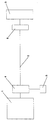
- number 1 indicates the generator of a welding machine, connected via a cable 2 to a mini wire-feeder 3 which comprises a motor-driven cable winding reel, a welding torch and a panel with the various machine controls.
- a control unit 4 is fitted to generator 1; the said control unit, which is already known in the form of hardware, comprises a programmable memory such as an EPROM memory in which the data that enable this specific machine to be controlled are stored.
- a programmable memory such as an EPROM memory in which the data that enable this specific machine to be controlled are stored.
- the controls of the control panel on the mini wire-feeder can be the same for any kind of machine, as interface 6 sends signals to control unit 4 in accordance with the parameters input from the control panel; the said control unit processes the said signals in accordance with the program stored in EPROM 5, which is specific to the generator to which the control unit is applied, and regulates the generator on the basis of the command received.
- All the mini wire-feeders can therefore be identical, even if fitted to different types of machine, as a control unit with a program that receives standard signals from the mini wire-feeder and converts them into signals suitable for the specific type of machine is fitted to each generator.
- the purpose of the interface is to ensure that the machine setting parameters are always displayed in the same way, even on different types of equipment, thus providing operators with a single system for controlling welding parameters so that they can be standardised in accordance with the same method.
- combinations of parameters or work programs, each corresponding to a different welding situation can be determined in the workshop on a sample welder and then input into all machines, even if different, to obtain the same operational result.
- the fact that the interface is fitted to the mini wire-feeder means that the cable bundle can also be standardised, and a single cable 2 used for all the machines.
- the mini wire-feeder is thus equipped with an interface able to interact with a control unit, and the operation of these two components is synchronised, with the advantage that each mini wire-feeder is no longer usable with a specific machine only, but is exchangeable with the others as required.
- the method in accordance with the invention offers significant advantages, as it enables the setting and management of all types of welding machine to be standardised and allows the machines to be modernised at a limited cost, so that the fleet of machines can be adapted to incorporate new technologies.
Landscapes
- Engineering & Computer Science (AREA)
- Theoretical Computer Science (AREA)
- Physics & Mathematics (AREA)
- Plasma & Fusion (AREA)
- Mechanical Engineering (AREA)
- Arc Welding Control (AREA)
- Lining Or Joining Of Plastics Or The Like (AREA)
Applications Claiming Priority (2)
| Application Number | Priority Date | Filing Date | Title |
|---|---|---|---|
| ITVI970148 | 1997-09-04 | ||
| ITVI970148 IT1302107B1 (it) | 1997-09-04 | 1997-09-04 | Metodo e dispositivi per la standardizzazione delle funzioni dicontrollo di macchine saldatrici e saldatrici dotate di detti |
Publications (2)
| Publication Number | Publication Date |
|---|---|
| EP0907118A2 true EP0907118A2 (de) | 1999-04-07 |
| EP0907118A3 EP0907118A3 (de) | 1999-06-16 |
Family
ID=11426449
Family Applications (1)
| Application Number | Title | Priority Date | Filing Date |
|---|---|---|---|
| EP98115559A Withdrawn EP0907118A3 (de) | 1997-09-04 | 1998-08-19 | Verfahren und Vorrichtung zur Standardisierung der Kontrollfunktionen von Schweigeräten und Geräten ausgerüstet mit dieser Vorrichtung |
Country Status (2)
| Country | Link |
|---|---|
| EP (1) | EP0907118A3 (de) |
| IT (1) | IT1302107B1 (de) |
Cited By (2)
| Publication number | Priority date | Publication date | Assignee | Title |
|---|---|---|---|---|
| WO2000023223A1 (de) * | 1998-10-16 | 2000-04-27 | Fronius Schweissmaschinen Produktion Gmbh & Co. Kg | Regelvorrichtung für ein schweissgerät |
| EP3263267B1 (de) | 2012-02-02 | 2019-06-26 | Lincoln Global, Inc. | Stromquelle- und drahtfördereranpassung |
Family Cites Families (3)
| Publication number | Priority date | Publication date | Assignee | Title |
|---|---|---|---|---|
| DE3110350A1 (de) * | 1980-03-17 | 1982-04-01 | Hitachi Seiko Ltd., Tokyo | Lichtbogenschweissvorrichtung |
| JPS5978781A (ja) * | 1982-10-27 | 1984-05-07 | Fanuc Ltd | 自動溶接機における溶接方法 |
| JPH01181976A (ja) * | 1988-01-14 | 1989-07-19 | Toyota Motor Corp | 溶接ワイヤ送給制御装置 |
-
1997
- 1997-09-04 IT ITVI970148 patent/IT1302107B1/it active IP Right Grant
-
1998
- 1998-08-19 EP EP98115559A patent/EP0907118A3/de not_active Withdrawn
Cited By (4)
| Publication number | Priority date | Publication date | Assignee | Title |
|---|---|---|---|---|
| WO2000023223A1 (de) * | 1998-10-16 | 2000-04-27 | Fronius Schweissmaschinen Produktion Gmbh & Co. Kg | Regelvorrichtung für ein schweissgerät |
| US6605800B1 (en) | 1998-10-16 | 2003-08-12 | Fronius Schweissmaschinen Produktion Gmbh & Co. Kg | Regulating device for a welding apparatus |
| EP3263267B1 (de) | 2012-02-02 | 2019-06-26 | Lincoln Global, Inc. | Stromquelle- und drahtfördereranpassung |
| EP2809473B1 (de) | 2012-02-02 | 2019-08-07 | Lincoln Global, Inc. | Abstimmung einer drahtförderung auf einer stromquelle |
Also Published As
| Publication number | Publication date |
|---|---|
| EP0907118A3 (de) | 1999-06-16 |
| ITVI970148A1 (it) | 1999-03-04 |
| IT1302107B1 (it) | 2000-07-26 |
Similar Documents
| Publication | Publication Date | Title |
|---|---|---|
| EP1207977B2 (de) | Schweissgerät mit kommunikationsschnittstelle und verfahren zum betreiben des schweissgerätes | |
| AT411880B (de) | Steuervorrichtung für ein schweissgerät | |
| US11179792B2 (en) | Torch for electric arc welding system | |
| US12233487B2 (en) | Automatic weld arc monitoring system | |
| EP1924385B1 (de) | Fernzugriffseinheit und verfahren zur verwaltung von über schnittstellen mit einem netzwerk verbundenen schweissgeräten | |
| EP3787828B1 (de) | Tragbare benutzerschnittstelle für ein schweisssystem | |
| US6605800B1 (en) | Regulating device for a welding apparatus | |
| WO2002047861A1 (de) | Verfahren zum verbinden mehrerer schweissgeräte sowie schweissgerät hierfür | |
| CN101687269A (zh) | 用于焊接电源的用户界面 | |
| EP1492642A1 (de) | Verfahren zur einstellung von parametern bei schweissgeräten | |
| JPH0538586A (ja) | 抵抗溶接システム | |
| AT407023B (de) | Steuervorrichtung zum steuern eines schweissgerätes sowie ein verfahren hierfür | |
| EP0907118A2 (de) | Verfahren und Vorrichtung zur Standardisierung der Kontrollfunktionen von Schweigeräten und Geräten ausgerüstet mit dieser Vorrichtung | |
| DE102004054816A1 (de) | Verfahren und System zur Übertragung eines Bearbeitungsprogramms | |
| EP0903195A1 (de) | System zur Ferneinstellung, -regulierung und -steuerung der Funktionen von Schweissmaschinen | |
| KR102150397B1 (ko) | 용접 시스템의 와이어 송급장치 | |
| EP1057567B1 (de) | Lichtbogenschweissversorgung, Lichtbogenschweissrobotsteuergerät, und Lichtbogenschweissgerät | |
| JPH05220580A (ja) | 溶接ロボットシステム | |
| KR20100069914A (ko) | 근거리 무선 통신을 이용한 용접 제어 시스템 및 방법 | |
| CA2334939A1 (en) | A plant for controlling process equipment | |
| JP2670870B2 (ja) | 溶接ロボットの制御装置 | |
| EP1417073A2 (de) | Fügesystem zum fügen von elementen auf bauteile, verfahren zum betreiben eines fügesystems und datenspeicher |
Legal Events
| Date | Code | Title | Description |
|---|---|---|---|
| PUAI | Public reference made under article 153(3) epc to a published international application that has entered the european phase |
Free format text: ORIGINAL CODE: 0009012 |
|
| AK | Designated contracting states |
Kind code of ref document: A2 Designated state(s): AT CH DE ES FI FR GB IT LI SE |
|
| AX | Request for extension of the european patent |
Free format text: AL;LT;LV;MK;RO;SI |
|
| PUAL | Search report despatched |
Free format text: ORIGINAL CODE: 0009013 |
|
| AK | Designated contracting states |
Kind code of ref document: A3 Designated state(s): AT BE CH CY DE DK ES FI FR GB GR IE IT LI LU MC NL PT SE |
|
| AX | Request for extension of the european patent |
Free format text: AL;LT;LV;MK;RO;SI |
|
| RIC1 | Information provided on ipc code assigned before grant |
Free format text: 6G 05B 19/00 A, 6G 05F 1/10 B, 6G 05F 5/00 B, 6B 23K 9/12 B, 6B 23K 9/095 B, 6B 23K 9/10 B |
|
| 17P | Request for examination filed |
Effective date: 19991201 |
|
| AKX | Designation fees paid |
Free format text: AT CH DE ES FI FR GB IT LI SE |
|
| AXX | Extension fees paid |
Free format text: SI PAYMENT 19991201 |
|
| 17Q | First examination report despatched |
Effective date: 20010125 |
|
| STAA | Information on the status of an ep patent application or granted ep patent |
Free format text: STATUS: THE APPLICATION IS DEEMED TO BE WITHDRAWN |
|
| 18D | Application deemed to be withdrawn |
Effective date: 20010606 |