EP0907158B1 - Anzeigesteuereinrichtung für eine Hintergrundbeleuchtung mit verbesserter Lichtausbeute - Google Patents
Anzeigesteuereinrichtung für eine Hintergrundbeleuchtung mit verbesserter Lichtausbeute Download PDFInfo
- Publication number
- EP0907158B1 EP0907158B1 EP98114929A EP98114929A EP0907158B1 EP 0907158 B1 EP0907158 B1 EP 0907158B1 EP 98114929 A EP98114929 A EP 98114929A EP 98114929 A EP98114929 A EP 98114929A EP 0907158 B1 EP0907158 B1 EP 0907158B1
- Authority
- EP
- European Patent Office
- Prior art keywords
- illumination
- backlight
- display
- section
- instruction
- Prior art date
- Legal status (The legal status is an assumption and is not a legal conclusion. Google has not performed a legal analysis and makes no representation as to the accuracy of the status listed.)
- Expired - Lifetime
Links
- 238000005286 illumination Methods 0.000 title claims description 148
- 230000006870 function Effects 0.000 claims description 15
- 230000008859 change Effects 0.000 claims description 9
- 238000004590 computer program Methods 0.000 claims description 7
- 238000004364 calculation method Methods 0.000 claims description 5
- 238000000034 method Methods 0.000 description 32
- 230000008569 process Effects 0.000 description 24
- 241001076195 Lampsilis ovata Species 0.000 description 18
- 239000004973 liquid crystal related substance Substances 0.000 description 11
- 238000010276 construction Methods 0.000 description 9
- 230000001747 exhibiting effect Effects 0.000 description 4
- 230000007423 decrease Effects 0.000 description 3
- 238000011161 development Methods 0.000 description 2
- 230000018109 developmental process Effects 0.000 description 2
- 238000010586 diagram Methods 0.000 description 2
- 230000006872 improvement Effects 0.000 description 2
- 230000009467 reduction Effects 0.000 description 2
- 230000001419 dependent effect Effects 0.000 description 1
- 230000000694 effects Effects 0.000 description 1
- 239000004065 semiconductor Substances 0.000 description 1
Images


Classifications
-
- H—ELECTRICITY
- H04—ELECTRIC COMMUNICATION TECHNIQUE
- H04W—WIRELESS COMMUNICATION NETWORKS
- H04W52/00—Power management, e.g. Transmission Power Control [TPC] or power classes
- H04W52/02—Power saving arrangements
- H04W52/0209—Power saving arrangements in terminal devices
- H04W52/0261—Power saving arrangements in terminal devices managing power supply demand, e.g. depending on battery level
- H04W52/0267—Power saving arrangements in terminal devices managing power supply demand, e.g. depending on battery level by controlling user interface components
- H04W52/027—Power saving arrangements in terminal devices managing power supply demand, e.g. depending on battery level by controlling user interface components by controlling a display operation or backlight unit
-
- G—PHYSICS
- G09—EDUCATION; CRYPTOGRAPHY; DISPLAY; ADVERTISING; SEALS
- G09G—ARRANGEMENTS OR CIRCUITS FOR CONTROL OF INDICATING DEVICES USING STATIC MEANS TO PRESENT VARIABLE INFORMATION
- G09G3/00—Control arrangements or circuits, of interest only in connection with visual indicators other than cathode-ray tubes
- G09G3/20—Control arrangements or circuits, of interest only in connection with visual indicators other than cathode-ray tubes for presentation of an assembly of a number of characters, e.g. a page, by composing the assembly by combination of individual elements arranged in a matrix no fixed position being assigned to or needed to be assigned to the individual characters or partial characters
- G09G3/34—Control arrangements or circuits, of interest only in connection with visual indicators other than cathode-ray tubes for presentation of an assembly of a number of characters, e.g. a page, by composing the assembly by combination of individual elements arranged in a matrix no fixed position being assigned to or needed to be assigned to the individual characters or partial characters by control of light from an independent source
- G09G3/3406—Control of illumination source
-
- G—PHYSICS
- G09—EDUCATION; CRYPTOGRAPHY; DISPLAY; ADVERTISING; SEALS
- G09G—ARRANGEMENTS OR CIRCUITS FOR CONTROL OF INDICATING DEVICES USING STATIC MEANS TO PRESENT VARIABLE INFORMATION
- G09G3/00—Control arrangements or circuits, of interest only in connection with visual indicators other than cathode-ray tubes
- G09G3/20—Control arrangements or circuits, of interest only in connection with visual indicators other than cathode-ray tubes for presentation of an assembly of a number of characters, e.g. a page, by composing the assembly by combination of individual elements arranged in a matrix no fixed position being assigned to or needed to be assigned to the individual characters or partial characters
- G09G3/34—Control arrangements or circuits, of interest only in connection with visual indicators other than cathode-ray tubes for presentation of an assembly of a number of characters, e.g. a page, by composing the assembly by combination of individual elements arranged in a matrix no fixed position being assigned to or needed to be assigned to the individual characters or partial characters by control of light from an independent source
- G09G3/36—Control arrangements or circuits, of interest only in connection with visual indicators other than cathode-ray tubes for presentation of an assembly of a number of characters, e.g. a page, by composing the assembly by combination of individual elements arranged in a matrix no fixed position being assigned to or needed to be assigned to the individual characters or partial characters by control of light from an independent source using liquid crystals
-
- G—PHYSICS
- G09—EDUCATION; CRYPTOGRAPHY; DISPLAY; ADVERTISING; SEALS
- G09G—ARRANGEMENTS OR CIRCUITS FOR CONTROL OF INDICATING DEVICES USING STATIC MEANS TO PRESENT VARIABLE INFORMATION
- G09G2320/00—Control of display operating conditions
- G09G2320/06—Adjustment of display parameters
- G09G2320/0613—The adjustment depending on the type of the information to be displayed
- G09G2320/062—Adjustment of illumination source parameters
-
- G—PHYSICS
- G09—EDUCATION; CRYPTOGRAPHY; DISPLAY; ADVERTISING; SEALS
- G09G—ARRANGEMENTS OR CIRCUITS FOR CONTROL OF INDICATING DEVICES USING STATIC MEANS TO PRESENT VARIABLE INFORMATION
- G09G2330/00—Aspects of power supply; Aspects of display protection and defect management
- G09G2330/02—Details of power systems and of start or stop of display operation
- G09G2330/021—Power management, e.g. power saving
-
- H—ELECTRICITY
- H04—ELECTRIC COMMUNICATION TECHNIQUE
- H04M—TELEPHONIC COMMUNICATION
- H04M1/00—Substation equipment, e.g. for use by subscribers
- H04M1/02—Constructional features of telephone sets
- H04M1/22—Illumination; Arrangements for improving the visibility of characters on dials
-
- Y—GENERAL TAGGING OF NEW TECHNOLOGICAL DEVELOPMENTS; GENERAL TAGGING OF CROSS-SECTIONAL TECHNOLOGIES SPANNING OVER SEVERAL SECTIONS OF THE IPC; TECHNICAL SUBJECTS COVERED BY FORMER USPC CROSS-REFERENCE ART COLLECTIONS [XRACs] AND DIGESTS
- Y02—TECHNOLOGIES OR APPLICATIONS FOR MITIGATION OR ADAPTATION AGAINST CLIMATE CHANGE
- Y02D—CLIMATE CHANGE MITIGATION TECHNOLOGIES IN INFORMATION AND COMMUNICATION TECHNOLOGIES [ICT], I.E. INFORMATION AND COMMUNICATION TECHNOLOGIES AIMING AT THE REDUCTION OF THEIR OWN ENERGY USE
- Y02D30/00—Reducing energy consumption in communication networks
- Y02D30/70—Reducing energy consumption in communication networks in wireless communication networks
Definitions
- the present invention relates to a display control device having an illuminating function and a storage medium therefor.
- the control device is applicable to a small-sized portable electronic system such as an electronic notebook or a portable information terminal.
- liquid crystal display devices semiconductors and electronics techniques
- numerous kinds of small-sized multi-functional portable electronic equipment have been commercialized.
- extension of lives of batteries as well as miniaturization is an important factor, and liquid crystal panels, which are low power displays and exhibit excellent display characteristics, are widely used.
- the liquid crystal panel is not a self-luminous device, it is difficult to read a screen of the panel under low light conditions. For this reason, a backlight is recently used for illuminating the liquid crystal display panel.
- a method of illuminating a liquid crystal display panel using an electroluminescent panel (an EL panel) as a backlight which is mounted on the rear side of the display panel provided with a semi-transmission type reflector is generally adopted.
- This method was initially applied to smaller-sized electronic devices such as electronic watches and pagers, and is now used for portable electronic devices having medium-sized screens such as electronic notebooks.
- the backlight consumes a lot of electric power and, when it is kept on for a long time, a battery life is greatly affected. Therefore, some backlights are designed to emit light of a reduced luminance as low as possible.
- the above (1) is widely used since it allows a user to activate the backlight for the given time period only when necessary.
- an EL panel is capable of emitting light on a one-character basis, and EL elements are driven only in a region where textual data or drawing data is to be displayed.
- this method of driving the EL elements it is possible to save power which would otherwise be necessary for driving EL elements in a region where textual data or drawing data is not displayed.
- the display is not easy to see in a dark environment even if the backlight is turned on to illuminate the display.
- an increase of the luminance will make the display easier to see, but the increase of the luminance will result in a rise in power consumption and therefore a decrease in the battery life.
- the backlight emits light for the given time regardless of the number of displayed characters. Accordingly, for example, in the case of an electronic notebook which has a relatively large screen and may display a lot of characters, the backlight may possibly go off before a user has finished reading all characters. If the backlight light-emission time is set longer, the backlight wastefully consumes the battery by staying on after all characters have been read, in the case where only a small number of characters are displayed.
- the method cannot be used for an electronic device such as an electronic notebook which requires key operation.
- the backlight light-emission control (3) of automatically turning on the backlight when the ambient brightness falls below the predetermined level by use of the brightness sensor cost increases.
- the backlight keeps producing light in dark conditions even when unnecessary, which results in a decrease of the battery life.
- Japanese Unexamined Patent Publication HEI 2(1990)-190895 discloses a liquid crystal display device with back light, including a video memory for storing data to be displayed on a liquid crystal panel and an EL memory for controlling the driving of an EL panel in dependence on the presence or absence of video information in the video memory. According to the method disclosed, a special EL panel is required, and the EL panel is driven in a rather complicated manner. In addition to that, consideration is not given to effect an extended light-producing time on the battery life.
- US-A-5347293 discloses a display device for motor vehicles comprising a display panel and a backlight, wherein a contrast switch-over is effected on the display panel in dependence on the brightness in front of the display panel.
- the present invention is to provide a display control device which allows reduction of power consumption by a backlight when data such as textual data or drawing data is displayed on a display panel with the backlight on.
- this object is accomplished by a display control device as defined in claim 1, and by a storage medium containing a computer program as defined in claim 9.
- the display control device of the present invention is constructed to have a display panel for displaying data containing textual and/or drawing data, a display buffer for storing data to be displayed on the display panel, a display control section for controlling display of the display panel, a backlight for illuminating the display panel, an illumination instruction section for outputting a backlight illumination instruction, and an illumination control section for controlling the illumination of the backlight according to the backlight illumination instruction from the illumination instruction section.
- the display control section changes a display configuration of the data to be displayed on the display panel when the illumination instruction section outputs the backlight illumination instruction.
- the display panel preferably include a liquid crystal display panel with a semi-transmission type reflector mounted on the rear side of the panel.
- the backlight is composed of an EL (electroluminescent) panel and is preferably constructed to be able to be assembled with being placed on the rear side of the liquid crystal display panel.
- the display buffer, the display control section and the illumination control section are preferably composed of a computer including a CPU, a ROM, a RAM, and an I/O port.
- the display buffer may be composed of a RAM
- the display control section and the illumination control section may be composed of a CPU.
- the illumination instruction section may preferably include an input device such as a keyboard or a transparent tablet formed on the surface of the display panel.
- visibility of data displayed on the display panel can be improved by changing display configurations (size, font, normal/reverse video, etc.) when the backlight is turned on to illuminate the display panel.
- the battery's life will extend in a portable electronic device driven by a battery which device includes the display control device of the present invention.
- the display control section may be constructed such that, when the illumination instruction section outputs the backlight illumination instruction, the display control section changes a display size of the data stored in the display buffer for displaying the data on the display panel.
- the displayed data e.g., textual data
- a display screen exhibiting good visibility to a user can be provided.
- the display buffer may be constructed to pre-store a plurality of display sizes for the data to be displayed on the display panel.
- the display sizes can be selected.
- the display control section may be constructed such that, when the illumination instruction section outputs the backlight illumination instruction, the display control section controls the display panel to display the data stored in the display buffer in reverse video.
- the control device of the invention may further comprise a count section for counting the number of characters of the data to be displayed on the display, wherein when the illumination instruction section outputs the backlight illumination instruction, the illumination control section changes a time period of illumination of the backlight according to the number of characters counted by the count section.
- the backlight can be set to be on for a proper time depending on the number of characters to be displayed. Thereby, even in the case where a large number of characters are displayed, the inconvenience of the backlight going off before a user have finished reading can be avoided. On the other hand, in the case where a small number of characters are displayed, the backlight can be prevented from producing light wastefully for a long period. Thus, the power consumption can be reduced and the life of the battery can increase.
- the control device of the invention may further comprise an illumination time period setting table storing a plurality of backlight illumination time periods in correspondence with the number of characters of the data to be displayed on the display panel, wherein when the illumination instruction section outputs the backlight illumination instruction, the illumination control section controls the illumination of the backlight according to the illumination time period read from the illumination time period setting table.
- the control device of the invention may further comprise an illumination time period setting table storing a backlight illumination time period per one character and a calculation section for calculating an illumination time period corresponding to the number of characters of the data to be displayed on the display panel by reference to the illumination time period setting table, wherein when the illumination instruction section outputs the backlight illumination instruction, the illumination control section controls the illumination of the backlight according to the illumination time period calculated by the calculation section.
- the control device of the invention may further comprise an illumination time period setting table storing a backlight illumination time period for every application, wherein when the illumination instruction section outputs the backlight illumination instruction, the illumination control section controls the illumination of the backlight according to the illumination time period for an application in use read from the illumination time period setting table.
- the backlight illumination time can easily be designated according to an application such as a schedule, telephone or memorandum application, the backlight can be kept on for a proper time according to not only the number of displayed characters but also the application. Therefore, a display screen convenient to a user can be provided.
- the illumination control section may comprise a notice section for informing that the backlight is going to be off a predetermined time before the backlight goes off.
- the notice section may be composed of a piezo-electric beeper.
- the present invention provides storage medium containing thereon a computer program for controlling a display control device including a display panel for displaying data containing textual and/or drawing data, a display buffer for storing the data to be displayed on the display panel, a backlight for illuminating the display panel and an illumination instruction section for outputting a backlight illumination instruction.
- the computer program performs the functions of causing a computer operation to control illumination of the backlight according to the backlight illumination instruction from the illumination instruction section; causing a computer operation to control display of the display panel; and causing a computer operation to change a display configuration of the data to be displayed on the display panel when the illumination instruction section outputs the backlight illumination instruction.
- the storage medium may further perform the functions of causing a computer operation to count the number of characters of the data stored in the display buffer to be displayed on the display panel; and causing a computer operation to change a time period of illumination of the backlight according to the counted number of characters.
- a display control device by installing the control program stored in the storage medium, a display control device can be obtained, which device can reduce power consumption by the backlight by improving the visibility of displayed data such as characters or drawings through changing the display configuration of the data when the backlight illuminates the display panel for displaying the data, and through changing the illuminating time period of the backlight according to the amount of the data.
- the present invention is now described in detail by way of example with reference to the accompanying drawings, which should not be construed to limit the scope of the invention.
- the present invention is explained as a display control device adapted to an electronic pocketbook which is a kind of portable electronic equipment.
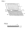
- Fig. 1 is a perspective view illustrating the appearance of an electronic pocketbook to which a display control device in accordance with the present invention is applied.
- the reference numerals 1, 4, 4a, 4b, 4c, 4d and 4e denote a display section, a key input section, an ON key, an OFF key, a function key, an alphanumeric input key and a backlight key, respectively.
- the display section 1 and the key input section 4 are joined together with a hinge.
- the electronic pocketbook can be closed with the display section 1 and the key input section inside.
- Electronic circuits and a battery for driving the electronic pocketbook are accommodated under the display section 1 and the key input section 4. The battery can be replaced from the bottom surface of the key input section 4.
- Fig. 2 is a schematic cross-sectional view illustrating the construction of the display section of the electronic pocketbook to which the display control device in accordance with the present invention is applied.
- the display section 1 is composed of a liquid crystal display panel 2 provided with a semi-transmission type reflector 2a on the bottom surface thereof and a backlight 3 using an EL panel.
- the backlight 3 is mounted on the bottom surface of the display panel 2 with intervention of the reflector 2a.
- the display section 1 is constructed such that characters or drawings displayed on the display panel 2 are seen by external light reflected by the semi-transmission type reflector 2a in a bright ambience and by light emitted by the backlight 3 and passing though the reflector 2a in a dark ambience.
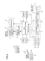
- Fig. 3 is a block diagram illustrating the structure of the electronic pocketbook to which the display control device in accordance with the present invention is applied.
- the reference numeral 5 denotes a CPU for generally controlling key input, data display, data processing, storage and the like.
- the reference numeral 6 denotes a ROM for storing programs to cause the CPU 5 to operate,
- the reference numeral 7 denotes a RAM for storing data about schedules, telephone numbers, etc. inputted by a user.
- the RAM 7 also serves as a work memory for the CPU 5.
- the reference numeral 8 denotes a display controller for controlling the display section 1 and causing data sent from the CPU 5 to be displayed on the display panel 2 of the display section 1.
- the key input section 4 is composed of the ON key 4a, OFF key 4b, function key 4c, alphanumeric input key 4d, and backlight key 4e.
- the ON key 4a and OFF key 4b are used for turning the power of the electronic pocketbook on and off, respectively.
- the function key 4c is used for switching applications such as a schedule, a telephone book, a memorandum, etc., and for performing various settings.
- the alphanumeric input key 4d is used for inputting data and performing various kinds of settings .
- an alphabet from A to Z, numerals and a number of symbols can be inputted.
- the backlight key 4e is actuated when the user needs to see displayed content in a dark environment. When this key is actuated, the backlight emits light for a predetermined time period and then goes off automatically.
- the reference numeral 9 denotes a timer to generate a basic clock signal for time display.
- the timer 9 is also used for schedule management.
- the reference numeral 10 denote a beeper to generate a touch sound when a key is actuated and an alarm sound.
- the beeper is also used to sound a notice beep for giving the advance notice of the backlight going off a predetermined time before the backlight actually goes off.
- the reference numeral 11 denotes a main battery for driving the electronic pocketbook.
- the reference numeral 12 denotes a back-up battery for retaining data and settings stored in the RAM 7 while the main battery 11 is being replaced, for example.
- the reference numeral 13 denotes a storage medium composed of an floppy disk (FD), CD-ROM or the like.
- FD floppy disk
- CD-ROM Compact Disc-ROM
- stored is the same program as the operational program of the present invention stored in the ROM 6.
- the program for executing the operation of the present invention can be read from the storage medium 13 into the RAM 7 through storage medium reading means (not shown), so that the same operation is executed as in the case where the program is stored in the ROM 6.
- the electric pocketbook of this embodiment has a number of applications such as a schedule, a telephone book, a memorandum application and the like.
- the applications can be switched by actuating the function key 4c.
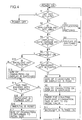
- Fig. 4 is a flowchart illustrating an operational process (1) in accordance with an embodiment of the invention. Referring to the flowchart of Fig. 4, explanation is given provided that data shown in Figs. 6(a) to 6(d) and Fig. 7 have been inputted to the RAM 7.
- an ON signal is inputted to the CPU 5 and operation starts. If this is the first time to use the electronic pocketbook, an initial display, for example, a schedule data input display, is displayed. If any data has already been stored, a display just before turning off the power supply is displayed.
- STEP S1 The CPU 5 is in a state of waiting for a key input from keys such as the OFF key, an application switch key, a displayed data change key or the backlight key. First, the CPU 5 checks the status of the OFF key. If the OFF key is actuated, the display is turned off and the power supply gets in an OFF state.
- STEP S2 If the OFF key is not actuated, the status of the application switch key is checked.
- STEP S3 If the application switch key is actuated, an application corresponding to the key operation is displayed. Then the process goes back to STEP S1 and the CPU 5 returns to the state of waiting for a key input.
- STEP S4 If the application switch key is not actuated, a key operation for changing displayed data is checked.
- STEP S5 If the key operation for changing displayed data is executed, designated data is displayed. Then the process goes back to STEP S1 and the CPU 5 returns to the state of waiting for a key input.
- the key operations for changing displayed data include key operations for displaying one case from a displayed list, for scrolling displayed data back and forth by an arrow key and for retrieving and displaying desired data using data retrieving function. Detailed explanation of these functions and specific operations is omitted.
- STEP S6 Whether the backlight is on or off is checked.
- STEP S7 If the backlight is off, the status of the backlight key is checked. If the backlight key is not actuated, the process goes to STEP1 and the CPU 5 returns to the state of waiting for a key input.
- STEP S8 If the backlight is on, the size of characters pre-set by the user are read out of the RAM 7.
- characters are stored in a plurality of sizes (e.g., three sizes) beforehand and the user can switch among the plural sizes for display of characters.
- Figs. 6(a) to 6(d) show a set (1) of exemplary screen displays in accordance with the embodiment
- Fig. 7 shows an exemplary screen display for setting the size of characters to be displayed in accordance with the embodiment.
- STEP S9 The CPU 5 switches the size of displayed characters from “Normal” to “Medium” on the basis of a size setting read out of the RAM 7, and send data to be displayed to the controller 8. Thereby, the screen switches from the display shown in Fig. 6(a) to that shown in Fig. 6(b).
- Fig. 6(a) is a normal display when the backlight is off.
- STEP S10 An initial value, e.g., 30 seconds, is set with a timer (TM) for controlling the illumination time of the backlight.
- TM timer
- STEP S11 After the backlight is turned on, the process goes back to STEP S1 and the CPU 5 returns to the state of waiting for a key input.
- the display control device of the embodiment has also the function of switching the size of characters on display during illumination of the backlight. While the backlight is on, the process goes from STEP S6 to STEP S12.
- STEP S12 The actuation of the backlight key is recognized.
- STEP S13 the size of displayed characters is switched.
- the size of characters on display switches every time when the backlight key is actuated. For example, the size switches that of Fig. 6(a), to that of Fig. 6 (b) , to that of Fig. 6(c) and then to that of Fig. 6(a) in this embodiment.
- STEP S14 If the backlight key is not actuated in STEP S12, whether the timer (TM) indicates the conclusion of the illumination time is checked. If the timer (TM) does not indicate the conclusion of the time, the process goes back to STEP S1 and the CPU 5 returns to the state of waiting for a key input.
- STEP S15 If the timer (TM) indicates the conclusion of the illumination time, the backlight is turned off.
- STEP S17 The size of displayed characters is switched back to the initial size (shown in Fig. 6(a)). The process goes back to STEP S1 and the CPU 5 returns to the state of waiting for a key input.
- Fig. 5 is a flowchart illustrating an operational process (2) in accordance with the embodiment.
- the process from STEP S21 to STEP S27 is the same as the process from STEP S1 to S7 in the flowchart shown in Fig. 4, and therefore explanation thereof is omitted.
- STEP S28 When the backlight key is actuated in STEP S27, the CPU 5 switches the display to reverse video and transfer data to be displayed to the display controller 8. Thereby, the screen switches from the display shown in Fig. 6(a) to that shown in Fig. 6(d).
- STEP S29 An initial value, e.g., 30 seconds, is set with the timer (TM) for controlling the illumination time of the backlight.
- STEP S30 After the backlight is turned on, the process goes back to STEP S21 and the CPU 5 returns to the state of waiting for a key input.
- STEP S31 Whether the timer (TM) indicates the conclusion of the illumination time is checked. If the timer does not indicate the conclusion, the process goes back to STEP S21 and the CPU 5 returns to the state of waiting for a key input.
- STEP S34 The reverse display is canceled and the display status returns to its initial state (not reversed as shown in Fig. 6(a)). Then the process goes back to STEP S21 and the CPU 5 returns to the state of waiting for a key input.
- the electronic pocketbook of the embodiment has three kinds of applications, that is, a schedule application, a telephone book application and a memorandum application. These applications can be switched using the function Key 4c.
- a schedule application a telephone book application
- a memorandum application a telephone book application
- These applications can be switched using the function Key 4c.
- explanation is given provided that data have already been inputted to the applications.
- Figs. 8(a) to 8(d) show a set (2) of exemplary screen displays in accordance with the embodiment.
- Fig. 8 (a) shows an exemplary screen display of the schedule application
- Fig. 8(b) shows an exemplary screen display of the telephone book application
- Fig. 8 (c) shows an exemplary screen display of the memorandum application (on which a large number of characters are displayed)
- Fig. 8(d) shows an exemplary screen display of the memorandum application (on which a small number of characters are displayed).
- Fig. 9 is a flowchart illustrating an operational process (3) in accordance with the embodiment.
- the process from STEP S41 to STEP S47 is the same as the process from STEP S1 to S7 in the flowchart shown in Fig. 4, and therefore explanation thereof is omitted.
- the illumination time is decided according to a display content, as described below, and is inputted to the timer (TM). Then, the backlight is turned on.
- STEP S48 When the backlight key is actuated, the number of characters on display is counted.
- STEP S49 The illumination time t1 is decided according to the counted number of characters.
- STEP S50 The illumination time t1 is inputted to a first timer (TM1).
- STEP S51 Time t2 obtained by reducing t0 from the illumination time t1 is inputted to a second timer (TM2) as a notice time for informing the user that the backlight is going off.
- TM2 second timer
- STEP S52 The backlight is turned on. The process goes back to STEP S1 and the CPU 5 returns to the state of waiting for a key input.
- Fig. 10 is an exemplary table showing correspondence between the number of displayed characters and the illumination time of the backlight in accordance with the embodiment.
- the correspondence between the number of displayed characters and the illumination time of the backlight is stored for every application in ROM 6 beforehand in the electronic pocketbook of the embodiment.
- the liquid crystal display panel is assumed to be capable of displaying 240 characters (30 characters ⁇ 8 lines) at maximum.
- the correspondence table the number of displayed characters is classified into a plurality of levels. The number of characters actually on display is compared with these levels, and the illumination time of the backlight is decided depending what level the actual number is belong to.
- the CPU 5 counts the number of characters on display in STEP S48, reads out the correspondence table from ROM 6 for comparison in STEP S49, and decides the illumination time t1.
- the correspondence is set for each of the applications because it is considered that more proper illumination time can be set when the illumination time is set for every application. For example,
- the illumination time t1 is 30 seconds according to the correspondence table of Fig. 10.
- the illumination time t1 is 30 seconds regardless of the number of characters.
- the illumination time t1 is 60 seconds.
- the illumination time t1 is 15 seconds.
- the illumination time can be properly set according to the display content and the number of displayed characters.
- the table indicating the correspondence between the number of characters on display and the illumination time of the backlight has been explained as being pre-stored in the ROM 6. It is noted, however, the correspondence table may be designed to accept changing and setting by the user and to be stored in the RAM 7.
- the illumination time may be set on a character basis. For example, an illumination time of 0.3 seconds is set for one character. This illumination time per character may be multiplied with the number of displayed characters to obtain the illumination time. In the case of the memorandum application for which the illumination time can be decided in proportion to the number of displayed characters, the illumination time can be properly decided by simple calculation.
- the illumination time per character is fixed and stored in the ROM 6, but the illumination time per character may be set and changed by the user and stored in the RAM 7. Further, in the case where the number of characters is small, the illumination time is extremely short. To avoid this, the minimum illumination time may be set to ensure about 10 seconds for illumination. The above-mentioned two ways of deciding the illumination time may also be used together depending on an application in use.
- the process branches off at STEP S46 to STEP S53, where the timers 1 and 2 (TM1 and TM2) are checked. These two timers are contained in the CPU 5, time is counted up in a hardware independently of operation of software, and a time-up signal is generated within the CPU 5.
- STEP S53 Whether the time has expired with the timer 1 (TM1) .
- STEP S54 If the time has expired with the timer 1, the backlight is turned off.
- STEP S55 The timer 1 (TM1) is reset. The process goes back to STEP S41 and the CPU 5 returns to the state of waiting a key input.
- STEP S56 If the time has not expired with the timer 1 (TM1), whether the time has expired with the timer 2 (TM2) is checked.
- STEP S58 Then, until the time expires with the timer 1, the actuation of the backlight key is checked.
- STEP S59 If the backlight key is actuated before the time expires with the timer 1, a time period t3 is set to the timer 1.
- the time period t3 is fixed value, for example, 15 seconds.
- the illumination time is extended for the time period t3.
- An object of this notice is to inform the user that the backlight is about to go off and allow the user to extend the illumination time, if necessary.
- a short sharp sound generated by the beeper 10 may be easily perceived by the user.
- the CPU5 may control the display controller 8 to flicker the backlight once or twice for a short time.
- the present invention presents the following advantages:
Landscapes
- Engineering & Computer Science (AREA)
- Physics & Mathematics (AREA)
- Computer Hardware Design (AREA)
- General Physics & Mathematics (AREA)
- Theoretical Computer Science (AREA)
- Chemical & Material Sciences (AREA)
- Crystallography & Structural Chemistry (AREA)
- Human Computer Interaction (AREA)
- Computer Networks & Wireless Communication (AREA)
- Signal Processing (AREA)
- Control Of Indicators Other Than Cathode Ray Tubes (AREA)
- Liquid Crystal Display Device Control (AREA)
Claims (10)
- Anzeigesteuereinrichtung mit:dadurch gekennzeichnet, dasseiner Anzeigetafel (2) zum Anzeigen von Daten, die Text- und/oder Zeichnungsdaten enthalten;einer Hintergrundbeleuchtung (3) zum Beleuchten der Anzeigetafel (2);einem Beleuchtungsbefehlsabschnitt (4, 4e) zum Ausgeben eines Hintergrundbeleuchtungs-Beleuchtungsbefehls;einem Beleuchtungssteuerabschnitt (5) zum Steuern der Beleuchtung der Hintergrundbeleuchtung entsprechend dem Hintergrundbeleuchtungs-Beleuchtungsbefehl vom Beleuchtungsbefehlsabschnitt (4, 4e); undeinem Anzeigesteuerabschnitt (8) zum Steuern der Anzeige durch die Anzeigetafel (2), der so ausgebildet ist, dass er die Anzeigekonfiguration der auf der Anzeigetafel (2) anzuzeigenden Daten ändert, wenn der Beleuchtungsbefehlsabschnitt (4, 4e) den Hintergrundbeleuchtungs-Beleuchtungsbefehl ausgibt;ein Anzeigepuffer (7) vorhanden ist, um auf der Anzeigetafel (2) anzuzeigende Daten zu speichern; undder Anzeigesteuerabschnitt (8) so ausgebildet ist, dass er die Anzeigegröße der im Anzeigepuffer (7) gespeicherten Daten zum Anzeigen derselben auf der Anzeigetafel (2) ändert, wenn der Beleuchtungsbefehlsabschnitt (4, 4e) den Hintergrundbeleuchtungs-Beleuchtungsbefehl ausgibt.
- Anzeigesteuereinrichtung nach Anspruch 1, bei der der Anzeigepuffer (7) so ausgebildet ist, dass er vorab eine Anzahl auswählbarer Anzeigegrößen für die auf der Anzeigetafel (2) anzuzeigenden Daten speichert.
- Anzeigesteuereinrichtung nach Anspruch 1, bei der der Anzeigesteuerabschnitt (8) so ausgebildet ist, dass er die Anzeigetafel (2) so steuert, dass sie die im Anzeigepuffer (7) gespeicherten Daten in invertierter Videodarstellung anzeigt, wenn der Beleuchtungsbefehlsabschnitt (4, 4e) den Hintergrundbeleuchtungs-Beleuchtungsbefehl ausgibt.
- Anzeigesteuereinrichtung nach Anspruch 1, ferner mit einem Zählabschnitt zum Zählen der Anzahl der Zeichen der auf der Anzeige anzuzeigenden Daten, wobei der Beleuchtungssteuerabschnitt (5) so ausgebildet ist, dass er die Beleuchtungszeitperiode der Hintergrundbeleuchtung entsprechend der Anzahl der vom Zählabschnitt gezählten Zeichen ändert, wenn der Beleuchtungsbefehlsabschnitt (4, 4e) den Hintergrundbeleuchtungs-Beleuchtungsbefehl ausgibt.
- Anzeigesteuereinrichtung nach Anspruch 1, ferner mit einer Beleuchtungszeitperiode-Einstelltabelle zum Speichern einer Anzahl von Beleuchtungszeitperioden für die Hintergrundbeleuchtung entsprechend der Anzahl von auf der Anzeigetafel anzuzeigenden Datenzeichen, wobei der Beleuchtungssteuerabschnitt (5) so ausgebildet ist, dass er die Beleuchtung der Hintergrundbeleuchtung entsprechend der aus der Beleuchtungszeitperiode-Einstelltabelle ausgelesenen Beleuchtungszeitperiode einstellt, wenn der Beleuchtungsbefehlsabschnitt (4, 4e) den Hintergrundbeleuchtungs-Beleuchtungsbefehl ausgibt.
- Anzeigesteuereinrichtung nach Anspruch 1, ferner mit einer Beleuchtungszeitperiode-Einstelltabelle zum Speichern einer Beleuchtungszeitperiode für die Hintergrundbeleuchtung pro Zeichen sowie einem Berechnungsabschnitt (5) zum Berechnen einer Beleuchtungszeitperiode entsprechend der Anzahl der auf der Anzeigetafel anzuzeigenden Datenzeichen unter Bezugnahme auf die Beleuchtungszeitperiode-Einstelltabelle, wobei der Beleuchtungssteuerabschnitt (5) so ausgebildet ist, dass er die Beleuchtung der Hintergrundbeleuchtung entsprechend der vom Beleuchtungsabschnitt berechneten Beleuchtungszeitperiode einstellt, wenn der Beleuchtungsbefehlsabschnitt (4, 4e) den Hintergrundbeleuchtungs-Beleuchtungsbefehl ausgibt.
- Anzeigesteuereinrichtung nach Anspruch 1, ferner mit einer Beleuchtungszeitperiode-Einstelltabelle zum Speichern einer Beleuchtungszeitperiode für die Hintergrundbeleuchtung für jede Softwareanwendung, wobei der Beleuchtungssteuerabschnitt (5) so ausgebildet ist, dass er die Beleuchtung der Hintergrundbeleuchtung entsprechend der aus der Beleuchtungszeitperiode-Einstelltabelle ausgelesenen Beleuchtungszeitperiode für die gerade verwendete Softwareanwendung einstellt, wenn der Beleuchtungsbefehlsabschnitt (4, 4e) den Hintergrundbeleuchtungs-Beleuchtungsbefehl ausgibt.
- Anzeigesteuereinrichtung nach Anspruch 1, bei der der Beleuchtungssteuerabschnitt (5) einen Hinweisabschnitt aufweist, um eine vorbestimmte Zeit vor dem Ausgehen der Hintergrundbeleuchtung darüber zu informieren, dass sie bald ausgehen wird.
- Speichermedium, das ein Computerprogramm zum Steuern einer Anzeigesteuereinrichtung (8) mit einer Anzeigetafel (2) zum Anzeigen von Text- und/oder Zeichnungsdaten enthaltenden Daten, eine Hintergrundbeleuchtung (3) zum Beleuchten der Anzeigetafel (2) und einen Beleuchtungsbefehlsabschnitt (4, 4e) zum Ausgeben eines Hintergrundbeleuchtungs-Beleuchtungsbefehls aufweist, wobei das Computerprogramm die folgenden Funktionen ausführt:dadurch gekennzeichnet, dass:Veranlassen einer Computerfunktion zum Steuern der Beleuchtung der Hintergrundbeleuchtung entsprechend dem Hintergrundbeleuchtungs-Beleuchtungsbefehl vom Beleuchtungsbefehlsabschnitt (4, 4e);Veranlassen einer Computerfunktion zum Steuern der Anzeige durch die Anzeigetafel (2) undVeranlassen einer Computerfunktion zum Ändern der Anzeigekonfiguration der auf der Anzeigetafel (2) anzuzeigenden Daten, wenn der Beleuchtungsbefehlsabschnitt (4, 4e) den Hintergrundbeleuchtungs-Beleuchtungsbefehl ausgibt;die Anzeigesteuereinrichtung einen Anzeigepuffer (7) zum Speichern der auf der Anzeigetafel anzuzeigenden Daten aufweist; unddas Computerprogramm die Funktion ausführt, dass sie eine Computerfunktion dazu veranlasst, die Anzeigegröße der im Anzeigepuffer (7) gespeicherten Daten zur Anzeige der Daten auf der Anzeigetafel (2) zu ändern, wenn der Beleuchtungsbefehlsabschnitt (4, 4e) den Hintergrundbeleuchtungs-Beleuchtungsbefehl ausgibt.
- Speichermedium nach Anspruch 9, bei dem das Computerprogramm ferner die folgenden Funktionen ausführt:Veranlassen einer Computerfunktion zum Zählen der Anzahl von Zeichen in den im Anzeigepuffer (7) gespeicherten, auf der Anzeigetafel (2) anzuzeigenden Daten; undVeranlassen einer Computerfunktion zum Ändern der Beleuchtungszeitperiode der Hintergrundbeleuchtung entsprechend der gezählten Anzahl von Zeichen.
Applications Claiming Priority (6)
| Application Number | Priority Date | Filing Date | Title |
|---|---|---|---|
| JP26332697A JPH11102171A (ja) | 1997-09-29 | 1997-09-29 | 表示制御装置及び表示制御プログラムを記録したコンピュータ読み取り可能な記録媒体 |
| JP26332697 | 1997-09-29 | ||
| JP263327/97 | 1997-09-29 | ||
| JP26332797A JPH11102173A (ja) | 1997-09-29 | 1997-09-29 | 表示制御装置及び表示制御プログラムを記録したコンピュータ読み取り可能な記録媒体 |
| JP263326/97 | 1997-09-29 | ||
| JP26332797 | 1997-09-29 |
Publications (2)
| Publication Number | Publication Date |
|---|---|
| EP0907158A1 EP0907158A1 (de) | 1999-04-07 |
| EP0907158B1 true EP0907158B1 (de) | 2001-11-14 |
Family
ID=26545967
Family Applications (1)
| Application Number | Title | Priority Date | Filing Date |
|---|---|---|---|
| EP98114929A Expired - Lifetime EP0907158B1 (de) | 1997-09-29 | 1998-08-07 | Anzeigesteuereinrichtung für eine Hintergrundbeleuchtung mit verbesserter Lichtausbeute |
Country Status (3)
| Country | Link |
|---|---|
| US (1) | US6219021B1 (de) |
| EP (1) | EP0907158B1 (de) |
| DE (1) | DE69802487T2 (de) |
Families Citing this family (29)
| Publication number | Priority date | Publication date | Assignee | Title |
|---|---|---|---|---|
| US6795929B2 (en) * | 1990-03-23 | 2004-09-21 | Matsushita Electric Industrial Co., Ltd. | Data processing apparatus |
| US6704783B1 (en) * | 1999-10-28 | 2004-03-09 | Fujitsu Limited | Reference state output system, reference state output method, and computer readable medium on which reference state output program is recorded |
| JP2001125894A (ja) * | 1999-10-29 | 2001-05-11 | Sony Corp | 文書編集処理装置及び文書編集処理方法およびプログラム提供媒体 |
| JP2001154642A (ja) * | 1999-11-30 | 2001-06-08 | Toshiba Corp | 情報処理装置 |
| JP4024444B2 (ja) | 1999-12-27 | 2007-12-19 | 株式会社東芝 | 無線電話装置 |
| WO2001048587A1 (en) * | 1999-12-28 | 2001-07-05 | Aiwa Co., Ltd. | Electronic device with display function |
| US6822629B2 (en) * | 2000-08-18 | 2004-11-23 | Semiconductor Energy Laboratory Co., Ltd. | Light emitting device |
| JP2002135374A (ja) * | 2000-10-26 | 2002-05-10 | Nec Corp | 携帯電話装置、携帯電話装置の制御方法、及びその制御プログラムを記録した記録媒体 |
| US7317439B2 (en) * | 2000-10-30 | 2008-01-08 | Matsushita Electric Industrial Co., Ltd. | Electronic apparatus and recording medium therefor |
| JP3675720B2 (ja) * | 2001-01-31 | 2005-07-27 | オムロン株式会社 | バックライト制御方法および表示装置 |
| US6712535B2 (en) * | 2001-04-30 | 2004-03-30 | Microsoft Corporation | Keyboard with improved lateral region |
| US6910818B2 (en) * | 2001-04-30 | 2005-06-28 | Microsoft Corporation | Keyboard with improved function and editing sections |
| US6726106B1 (en) * | 2002-04-02 | 2004-04-27 | Good Technology, Inc. | Power management and device illumination mechanisms for a personal digital assistant |
| US6664744B2 (en) * | 2002-04-03 | 2003-12-16 | Mitsubishi Electric Research Laboratories, Inc. | Automatic backlight for handheld devices |
| JP2004053694A (ja) | 2002-07-16 | 2004-02-19 | Sharp Corp | 表示装置、文字・図形表示制御方法、文字・図形表示プログラムおよび可読記録媒体 |
| KR100471070B1 (ko) * | 2002-07-29 | 2005-03-10 | 삼성전자주식회사 | 디스플레이장치 및 디스플레이장치의 조명장치제어방법 |
| US7663597B2 (en) * | 2003-07-16 | 2010-02-16 | Honeywood Technologies, Llc | LCD plateau power conservation |
| US7145558B2 (en) * | 2003-09-03 | 2006-12-05 | Motorola, Inc. | Selective illumination of regions of an electronic display |
| US7221964B2 (en) | 2004-02-27 | 2007-05-22 | Research In Motion Limited | LCD backlight duration proportional to amount of information on the LCD display screen |
| EP2175621A1 (de) * | 2004-02-27 | 2010-04-14 | Research in Motion Limited | LCD-Hintergrundbeleuchtungsdauer proportional zur Menge der angezeigten Information auf dem LCD-Bildschirm |
| DE112005003759A5 (de) * | 2005-09-16 | 2008-08-28 | Siemens Aktiengesellschaft | Elektrisches Feldgerät mit einer Anzeigevorrichtung |
| US9123189B2 (en) * | 2007-02-12 | 2015-09-01 | The Boeing Company | System and method for point-of-use instruction |
| US20090158221A1 (en) * | 2007-12-17 | 2009-06-18 | Nokia Corporation | Device feature manipulation based on presented content |
| CN101465952A (zh) * | 2007-12-21 | 2009-06-24 | 鸿富锦精密工业(深圳)有限公司 | 电子装置 |
| US20090207121A1 (en) * | 2008-02-19 | 2009-08-20 | Yung-Ho Shih | Portable electronic device automatically controlling back light unit thereof and method for the same |
| JP5759686B2 (ja) | 2009-08-06 | 2015-08-05 | 株式会社半導体エネルギー研究所 | 表示装置 |
| EP2640047B1 (de) | 2010-11-10 | 2016-08-03 | NEC Corporation | Tragbares endgerät und kommunikationssteuerverfahren |
| RU2523040C2 (ru) | 2012-10-02 | 2014-07-20 | ЭлДжи ЭЛЕКТРОНИКС ИНК. | Регулировка яркости экрана для мобильного устройства |
| WO2014089837A1 (en) * | 2012-12-14 | 2014-06-19 | Hewlett-Packard Development Company, L.P. | Dimming a display device |
Family Cites Families (6)
| Publication number | Priority date | Publication date | Assignee | Title |
|---|---|---|---|---|
| DE3830695A1 (de) | 1988-09-09 | 1990-03-22 | Bosch Gmbh Robert | Anzeigevorrichtung fuer kraftfahrzeuge |
| JPH02190895A (ja) | 1989-01-20 | 1990-07-26 | Nec Corp | バックライト付液晶表示装置 |
| US5233333A (en) * | 1990-05-21 | 1993-08-03 | Borsuk Sherwin M | Portable hand held reading unit with reading aid feature |
| KR940001691B1 (ko) * | 1990-06-25 | 1994-03-05 | 가부시기가이샤 도시바 | 배터리 구동식 퍼스널 컴퓨터 |
| JP3764504B2 (ja) | 1995-02-28 | 2006-04-12 | ソニー株式会社 | 液晶表示装置 |
| WO1997003432A1 (en) | 1995-07-13 | 1997-01-30 | Motorola Inc. | Method and apparatus for backlighting a display for different times in a battery powered device |
-
1998
- 1998-07-29 US US09/124,086 patent/US6219021B1/en not_active Expired - Lifetime
- 1998-08-07 DE DE69802487T patent/DE69802487T2/de not_active Expired - Lifetime
- 1998-08-07 EP EP98114929A patent/EP0907158B1/de not_active Expired - Lifetime
Also Published As
| Publication number | Publication date |
|---|---|
| DE69802487T2 (de) | 2002-05-23 |
| EP0907158A1 (de) | 1999-04-07 |
| DE69802487D1 (de) | 2001-12-20 |
| US6219021B1 (en) | 2001-04-17 |
Similar Documents
| Publication | Publication Date | Title |
|---|---|---|
| EP0907158B1 (de) | Anzeigesteuereinrichtung für eine Hintergrundbeleuchtung mit verbesserter Lichtausbeute | |
| JP3438693B2 (ja) | 表示部付き電子機器 | |
| US7616197B1 (en) | Method and apparatus for user selectable display mode for intelligently enhancing battery life | |
| CN100555402C (zh) | 电子显示器区域的选择性照明 | |
| KR100399873B1 (ko) | 전력 절약 백라이트 제어를 갖는 휴대용 단말 장치 | |
| US7268775B1 (en) | Dynamic brightness range for portable computer displays based on ambient conditions | |
| KR100662937B1 (ko) | 백라이트가 마련된 정보 단말 기기 | |
| JP3994516B2 (ja) | 液晶表示装置 | |
| JP2001273055A (ja) | 携帯型情報処理装置および同装置のシステム起動方法 | |
| KR100821758B1 (ko) | 디스플레이 시스템 및 그 전원 제어 방법 | |
| JPH10207400A (ja) | 液晶表示装置及びその光源制御方法 | |
| JPH11102173A (ja) | 表示制御装置及び表示制御プログラムを記録したコンピュータ読み取り可能な記録媒体 | |
| US20050104805A1 (en) | Portable electronic apparatus | |
| JP2004274570A (ja) | 携帯機器におけるキーバックライトの制御方法 | |
| EP1202243A2 (de) | Mobiltelefon mit regelbarer Anzeigen-Beleuchtung | |
| CN101105921B (zh) | 信息处理装置和控制方法 | |
| JPH11284712A (ja) | バックライトon/off機能付き携帯電話機 | |
| KR20090124089A (ko) | 디스플레이를 부분적으로 활성화하는 방법 및 장치 | |
| JPH11102171A (ja) | 表示制御装置及び表示制御プログラムを記録したコンピュータ読み取り可能な記録媒体 | |
| JPH1152930A (ja) | バックライト制御装置およびそのプログラム記録媒体 | |
| KR100697073B1 (ko) | 휴대단말기 및 그 액정화면 보호방법 | |
| KR100819261B1 (ko) | 이동 통신 단말의 백라이트 동작 제어 방법 및 장치 | |
| KR100346215B1 (ko) | 무선통신 단말기의 백라이트 제어장치 및 그 제어방법 | |
| JP2000036861A (ja) | 携帯端末装置 | |
| JP2555319Y2 (ja) | 電子機器 |
Legal Events
| Date | Code | Title | Description |
|---|---|---|---|
| PUAI | Public reference made under article 153(3) epc to a published international application that has entered the european phase |
Free format text: ORIGINAL CODE: 0009012 |
|
| AK | Designated contracting states |
Kind code of ref document: A1 Designated state(s): DE FR GB |
|
| AX | Request for extension of the european patent |
Free format text: AL;LT;LV;MK;RO;SI |
|
| 17P | Request for examination filed |
Effective date: 19990728 |
|
| AKX | Designation fees paid |
Free format text: DE FR GB |
|
| 17Q | First examination report despatched |
Effective date: 20000313 |
|
| GRAG | Despatch of communication of intention to grant |
Free format text: ORIGINAL CODE: EPIDOS AGRA |
|
| GRAG | Despatch of communication of intention to grant |
Free format text: ORIGINAL CODE: EPIDOS AGRA |
|
| GRAG | Despatch of communication of intention to grant |
Free format text: ORIGINAL CODE: EPIDOS AGRA |
|
| GRAH | Despatch of communication of intention to grant a patent |
Free format text: ORIGINAL CODE: EPIDOS IGRA |
|
| GRAH | Despatch of communication of intention to grant a patent |
Free format text: ORIGINAL CODE: EPIDOS IGRA |
|
| GRAA | (expected) grant |
Free format text: ORIGINAL CODE: 0009210 |
|
| AK | Designated contracting states |
Kind code of ref document: B1 Designated state(s): DE FR GB |
|
| REF | Corresponds to: |
Ref document number: 69802487 Country of ref document: DE Date of ref document: 20011220 |
|
| REG | Reference to a national code |
Ref country code: GB Ref legal event code: IF02 |
|
| ET | Fr: translation filed | ||
| PLBE | No opposition filed within time limit |
Free format text: ORIGINAL CODE: 0009261 |
|
| STAA | Information on the status of an ep patent application or granted ep patent |
Free format text: STATUS: NO OPPOSITION FILED WITHIN TIME LIMIT |
|
| 26N | No opposition filed | ||
| PGFP | Annual fee paid to national office [announced via postgrant information from national office to epo] |
Ref country code: DE Payment date: 20130731 Year of fee payment: 16 |
|
| PGFP | Annual fee paid to national office [announced via postgrant information from national office to epo] |
Ref country code: GB Payment date: 20130807 Year of fee payment: 16 Ref country code: FR Payment date: 20130808 Year of fee payment: 16 |
|
| REG | Reference to a national code |
Ref country code: DE Ref legal event code: R119 Ref document number: 69802487 Country of ref document: DE |
|
| GBPC | Gb: european patent ceased through non-payment of renewal fee |
Effective date: 20140807 |
|
| REG | Reference to a national code |
Ref country code: DE Ref legal event code: R119 Ref document number: 69802487 Country of ref document: DE Effective date: 20150303 |
|
| REG | Reference to a national code |
Ref country code: FR Ref legal event code: ST Effective date: 20150430 |
|
| PG25 | Lapsed in a contracting state [announced via postgrant information from national office to epo] |
Ref country code: DE Free format text: LAPSE BECAUSE OF NON-PAYMENT OF DUE FEES Effective date: 20150303 Ref country code: GB Free format text: LAPSE BECAUSE OF NON-PAYMENT OF DUE FEES Effective date: 20140807 |
|
| PG25 | Lapsed in a contracting state [announced via postgrant information from national office to epo] |
Ref country code: FR Free format text: LAPSE BECAUSE OF NON-PAYMENT OF DUE FEES Effective date: 20140901 |