EP0907172A1 - Dispositif de chargement de support d' enregistrement - Google Patents
Dispositif de chargement de support d' enregistrement Download PDFInfo
- Publication number
- EP0907172A1 EP0907172A1 EP98307899A EP98307899A EP0907172A1 EP 0907172 A1 EP0907172 A1 EP 0907172A1 EP 98307899 A EP98307899 A EP 98307899A EP 98307899 A EP98307899 A EP 98307899A EP 0907172 A1 EP0907172 A1 EP 0907172A1
- Authority
- EP
- European Patent Office
- Prior art keywords
- package
- disk
- contact
- loading
- recording medium
- Prior art date
- Legal status (The legal status is an assumption and is not a legal conclusion. Google has not performed a legal analysis and makes no representation as to the accuracy of the status listed.)
- Withdrawn
Links
- 230000006870 function Effects 0.000 claims description 2
- 238000003780 insertion Methods 0.000 abstract description 11
- 230000037431 insertion Effects 0.000 abstract description 11
- 238000004140 cleaning Methods 0.000 abstract description 6
- 230000007547 defect Effects 0.000 abstract description 2
- 239000004020 conductor Substances 0.000 description 11
- 238000005452 bending Methods 0.000 description 7
- 238000001746 injection moulding Methods 0.000 description 2
- 238000005192 partition Methods 0.000 description 2
- 229920003002 synthetic resin Polymers 0.000 description 2
- 239000000057 synthetic resin Substances 0.000 description 2
- RYGMFSIKBFXOCR-UHFFFAOYSA-N Copper Chemical compound [Cu] RYGMFSIKBFXOCR-UHFFFAOYSA-N 0.000 description 1
- 230000015572 biosynthetic process Effects 0.000 description 1
- 239000000470 constituent Substances 0.000 description 1
- 239000011889 copper foil Substances 0.000 description 1
- 230000002950 deficient Effects 0.000 description 1
- 230000003292 diminished effect Effects 0.000 description 1
- 230000003467 diminishing effect Effects 0.000 description 1
- 239000000428 dust Substances 0.000 description 1
- PCHJSUWPFVWCPO-UHFFFAOYSA-N gold Chemical compound [Au] PCHJSUWPFVWCPO-UHFFFAOYSA-N 0.000 description 1
- 229910052737 gold Inorganic materials 0.000 description 1
- 239000010931 gold Substances 0.000 description 1
- 239000000463 material Substances 0.000 description 1
- 229910044991 metal oxide Inorganic materials 0.000 description 1
- 230000004048 modification Effects 0.000 description 1
- 238000012986 modification Methods 0.000 description 1
- 238000000465 moulding Methods 0.000 description 1
- 230000003287 optical effect Effects 0.000 description 1
- 238000007747 plating Methods 0.000 description 1
- 229920005989 resin Polymers 0.000 description 1
- 239000011347 resin Substances 0.000 description 1
Images


Classifications
-
- G—PHYSICS
- G11—INFORMATION STORAGE
- G11B—INFORMATION STORAGE BASED ON RELATIVE MOVEMENT BETWEEN RECORD CARRIER AND TRANSDUCER
- G11B23/00—Record carriers not specific to the method of recording or reproducing; Accessories, e.g. containers, specially adapted for co-operation with the recording or reproducing apparatus ; Intermediate mediums; Apparatus or processes specially adapted for their manufacture
- G11B23/30—Record carriers not specific to the method of recording or reproducing; Accessories, e.g. containers, specially adapted for co-operation with the recording or reproducing apparatus ; Intermediate mediums; Apparatus or processes specially adapted for their manufacture with provision for auxiliary signals
-
- G—PHYSICS
- G11—INFORMATION STORAGE
- G11B—INFORMATION STORAGE BASED ON RELATIVE MOVEMENT BETWEEN RECORD CARRIER AND TRANSDUCER
- G11B17/00—Guiding record carriers not specifically of filamentary or web form, or of supports therefor
- G11B17/22—Guiding record carriers not specifically of filamentary or web form, or of supports therefor from random access magazine of disc records
- G11B17/30—Guiding record carriers not specifically of filamentary or web form, or of supports therefor from random access magazine of disc records wherein the playing unit is moved according to the location of the selected record
-
- G—PHYSICS
- G11—INFORMATION STORAGE
- G11B—INFORMATION STORAGE BASED ON RELATIVE MOVEMENT BETWEEN RECORD CARRIER AND TRANSDUCER
- G11B17/00—Guiding record carriers not specifically of filamentary or web form, or of supports therefor
- G11B17/22—Guiding record carriers not specifically of filamentary or web form, or of supports therefor from random access magazine of disc records
-
- G—PHYSICS
- G11—INFORMATION STORAGE
- G11B—INFORMATION STORAGE BASED ON RELATIVE MOVEMENT BETWEEN RECORD CARRIER AND TRANSDUCER
- G11B33/00—Constructional parts, details or accessories not provided for in the other groups of this subclass
- G11B33/12—Disposition of constructional parts in the apparatus, e.g. of power supply, of modules
- G11B33/121—Disposition of constructional parts in the apparatus, e.g. of power supply, of modules the apparatus comprising a single recording/reproducing device
Definitions
- the present invention relates to a recording medium loading device for loading into the body of the device a package which contains a single or plural disks such as a CD, a CD-ROM, a DVD, and/or a PD, or a package which contains recording means other than disks.
- both a disk for reproduction only and a recordable disk such as a combination of CD or CD-ROM and DVD-RAM, or a combination of DVD-ROM and DVD-RAM, are housed within a single disk package and the package is loaded into the disk unit.
- TOC data for example, of each of the loaded disks is read out using an optical head and determination is made as to the type of the disk and the contents of recorded information.
- the difference in thickness from the cover surface to the recording surface of the disk is detected or the track density is detected to determine the type of the disk. In this case, however, a long time is required from the time when the disk is loaded up to the time when its type is determined and a shift is made to a reproducing operation.
- FIG. 9 is a schematic sectional view showing a cassette holder of a digital video device body.
- a connection terminal 32 of a memory board is attached to a side end face 31a of a cassette tape 31 of DVC.
- a contact 34 formed by a metallic plate spring or the like.
- the cassette tape 31 is inserted into the device body while the connection terminal 32 of the memory board slides on the contact 34 provided on the cassette holder side.
- the elastic force of the contact 34 acts as a resistance force during loading of the cassette tape 31, thus giving rise to the drawback that the cassette tape inserting load is large and so is the cassette tape ejecting load.
- connection mechanism as shown in FIG. 9 is applied to a disk package loading structure in which the foregoing disk package containing plural disks is inserted longitudinally into the device body, the distance of the sliding motion between the wall surface of the inserted disk package and the contact becomes long, so that not only a load is imposed always on the disk package but also the contact slides a long distance on any other portion than the connection terminal of the cassette pack, for example the surface of a plastic wall.
- the plastic wall surface is scraped by the contact and hence not only the cassette pack is flawed but also the contact is stained, thus easily causing a defective connection between the contact and the connection terminal on the package side.
- connection mechanism arise not only in a disk-containing package but also in a tape-containing package or a package containing a single or plural memory elements.
- the present invention solves the above-mentioned problems of the prior art and it is an object of the invention to provide a recording medium loading device wherein a contact provided on the device body side is prevented from sling long on any other portion than a connection terminal of the package when a package containing recording mediums such as disks is loaded into the body of the device, thereby diminishing the package insertion load and preventing the contact from being stained.
- a recording medium loading device in which a connection terminal for connection with the exterior is provided in a package within which a recording medium is housed is provided, and the package is capable of being loaded into or unloaded from a body of the device, wherein in the device body are provided a contact support member having a contact and a moving member adapted to move in interlock with loading of the package, the contact support member being supported movably between a retracted position in which the contact is spaced apart from the package and a connecting position in which the contact is brought into contact with the connection terminal, the contact support member being the retracted position when the package is loaded into the device body and being moved to the connecting position by the moving member when the moving member moves after loading of the package.
- the contact provided on the device body side is prevented from coming into sliding contact with the package surface, whereby the package inserting load can be diminished and there is no fear of the contact being stained by its sliding contact with the package surface.
- the connection between the contact and the package-side connection terminal can be ensured.
- a disk as a recording medium is housed within the package, and the package is provided with a discriminating means having the foregoing connection terminal to detect at least either the type of the disk or recorded contents of the disk.
- a plurality of disks as recording mediums are accommodated within a package and the package is provided with a discriminating means having the foregoing connection terminal to detect at least either the type of each disk or recorded contents of each disk.
- the discriminating means is a memory board having a memory element.
- it may be of the type capable of expressing information of plural bits according to the number of connection terminals which are conductive with the contact.
- the contact and the contact support member are opposed to the position where one side of the package to be loaded passes.
- the contact support member moves to the connecting position immediately before the loading of the package into the device body is completed, and the contact and the connection terminal slide with respect to each other with the final loading motion of the package after contact of both contact and connection terminal.
- the package is inserted in parallel with a longitudinal direction (e.g. the disk surface direction), and the package is provided with a connection terminal on a side face thereof which extends in the package inserting direction.
- a longitudinal direction e.g. the disk surface direction
- the package is provided with a connection terminal on a side face thereof which extends in the package inserting direction.
- self-cleaning of the conductive portion can be expected by the sliding contact of the contact and the connection terminal at the final stage of package loading.
- the moving member not only moves while being pushed by the package being loaded but also functions as an eject member for pushing out the package in the ejecting direction when the package after loading is unlocked.
- the moving member may be an eject member which projects forward of the device when the package has been loaded and which is operated for ejection when the package is to be ejected, or it may be a moving member of another mechanism.
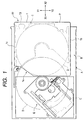
- FIG. 1 is a sectional plan view of a disk unit for loading therein of a disk package according to an embodiment of the present invention and FIG. 2 is a longitudinal sectional view thereof.
- the disk unit shown in FIGS. 1 and 2 has a housing A which is rectangular in plan.
- a package loading area B for loading a disk package P
- a disk driving area C In the disk driving area C is disposed a disk drive means E for driving a disk D after drawn out from the disk package P.
- the disk package P is inserted in X direction in FIGS. 1 and 2 into the housing A of the disk unit through an insertion port A1 formed in a longitudinally front position of the rectangular shape of the housing and is loaded into the package loading area B.
- FIG. 3 is a perspective view showing the appearance of a bottom side of the disk package.
- the disk package P is formed by a synthetic resin case 1, with an opening la being formed on X1 side in the figure.
- the opening la is for drawing out such tray T and disk D as indicated with dotted lines in FIG. 1. Through the opening la there are performed delivery and receipt of the disk D with respect to the disk drive means E.
- a plurality of horizontal ribs are formed on the inner surfaces of both left side plate 1b and right side plate 1c of the case 1 so that both right and left side edges of the tray T are slidable in X direction while being guided by adjacent such ribs.
- In the interior of the case 1 are formed plural stages horizontal ribs and, for example, five trays T as shown in FIG. 2 are accommodated within the case so that they can be drawn out.
- a disk having a diameter of 12 cm and a disk having a diameter of 8 cm there can be received a disk having a diameter of 12 cm and a disk having a diameter of 8 cm.
- ROM disks include CD and DVD-ROM, while examples of RAM disks include PD and DVD-RAM.
- a single CD is an example of a disk having a diameter of 8 cm.
- a memory board M as an example of the discriminating means is provided on an inner surface side of a bottom le of the disk package P.
- the memory board M is formed by fixing a memory element 2 onto a printed circuit board 5 which has a printed wiring of copper foil, for example.
- the printed circuit board 5 is provided with connection terminals 3 for connection between the memory element 2 and the exterior.
- the connection terminals 3 are exposed to the exterior from a rectangular hole 1f formed in the bottom 1e.
- the memory element 2 of the memory board M is, for example, an electrically writable RAM type IC chip which stores the types of all the disks D housed within the disk package P and index information of each disk package P.
- two guide grooves 4 are formed respectively in X and Y directions in the bottom le of the disk package P.
- the guide groove 4 formed in X direction is used when the disk package P is inserted in X1 direction into the body of the device (the disk unit), as shown in FIG. 1, while the guide groove 4 formed in Y direction is for a disk unit of the type in which the disk package P is inserted in Y1 direction.
- At the front ends (X1 and Y1 sides in the figure) of the guide grooves 4, 4 are respectively formed expanded portions 4a each defined by slant portions 4a1 and 4a2.
- lock grooves 4b are formed in the innermost portions on X2 and Y2 sides, respectively.
- the disk package P containing various disks D is inserted and loaded into the disk loading area B through the insertion port A1 of the housing A shown in FIGS. 1 and 2.
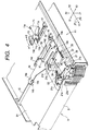
- FIG. 4 is a perspective view showing a mechanical structure from the bottom side (back side) of the disk unit which mechanical structure is provided on the bottom of the package loading area of the housing.
- the numeral 11 appearing in FIG. 4 denotes a lock member formed by injection molding of a synthetic resin for example.
- the lock member 11 is rotatable about a support shaft lla as fulcrum.
- An urging member S1 such as, for example, a coiled spring is stretched between a hole 11b formed in the lock member 11 and a retaining portion 12 formed by bending from the housing A. With the urging member S1, the lock member 11 is urged in the direction of ⁇ 1 in the figure.
- a front end portion 11c of the lock member 11 is bent in Z1 direction in the figure and is inserted into a sectorial hole 13 formed in the housing A.
- a generally triangular projection 11d is integral with the front end portion 11c and is projecting in Z1 direction into the package loading area B for the disk package P.
- a moving plate 14 serving as both a moving member and an eject member.
- the moving plate 14 which is formed by pressing a metallic plate, is movable on the bottom B1 in X direction in the figure through four slide portions 14a which are formed in V shape by molding on end sides in both X1 and X2 directions.
- a receiving portion 14b which is bent in T shape in Z1 direction in the figure.
- the receiving portion 14b is inserted in to a guide groove 15 formed in the bottom B1.
- a guide slot 14d into which is inserted a T-shaped projection 17 which is formed by bending from the bottom B1. Therefore, the moving plate 14 can move linearly in X direction along the guide slots 15 and 14d.
- a push-up piece 14e by bending, which can come into abutment with a to-be-pushed-up portion 21d of a contact mechanism portion 20 to be described later.
- An urging member (eject urging member) S2 such as, for example, a coiled spring is stretched between a retaining hole 14c formed in the moving plate 14 and a retaining portion 16 formed by bending from the bottom B1 of the package loading area B. With an urging force of the urging member S2, the moving plate 14 is urged in X2 direction in the figure at all times.
- a contact mechanism portion 20 which comprises a rotary member 21 and a contact support member 22 fixed to the rotary member.
- the rotary member 21 which is formed by bending a metallic plate or the like in a generally U-shape, is provided at both ends thereof with upright pieces 21a, 21b, a retaining portion 21c and the to-be-pushed-up portion 21d.
- the upright pieces 21a and 21b are rotatably supported on a rotating shaft 24 which is mounted horizontally between support pieces 23a and 23b (see FIG. 8) formed by bending from the bottom B1.
- a mounting portion 21e which extends in X2 direction in the figure with respect to the rotating shaft 24.
- the contact support member 22 is fixed to the mounting portion with screws or the like.
- an urging member S3 such as, for example, a coiled spring.
- the contact support member 22 (mounting portion 21e) side of the contact mechanism portion 20 is urged continually about the rotating shaft 24 in a direction ( ⁇ 1 direction in the figure) away from the bottom plate B1.
- FIG. 5 shows an example of a contact terminal, in which FIG. 5A is a plan view and FIG. 5B is a sectional view taken on line 5B-5B in FIG. 5A.
- the contact support member 22 shown in FIG. 5 comprises a base 25 formed by, for example, injection molding of a resin material having an electrical insulating property and conductors 26 each obtained by plating an elastic wire with gold for example.
- a base 25 formed by, for example, injection molding of a resin material having an electrical insulating property and conductors 26 each obtained by plating an elastic wire with gold for example.
- the base 25 are defined a plurality of compartments 25b by a plurality of partition walls 25a which are formed in X direction in the figure.
- a support shaft 27, which extends in Y axis direction, is inserted through X2-side end portions of the partition walls 25.
- each conductor 26 is formed with a torsion spring portion 26b.
- One side of each conductor 26 with respect to the torsion spring portion 26b is bent in a triangular shape having a contact 26a at the top thereof and also having a retaining portion 26c formed by bending at an end thereof.
- the torsion spring portion 26b is fitted on the support shaft 27 and the retaining portion 26c is engaged with a retaining piece 25c which is integral with the base 25.
- the other side of the conductor 26 is guided along a groove 25d formed in the base 25 and is exposed in X1 direction in the figure through an insertion hole 25e formed on an extension line of the groove 25d.
- the end portion of the conductor 26 exposed from the insertion hole 25e is connected through a distribution cable or the like to an electric circuitry (not shown) of, for example, a computer disposed within the disk unit.
- each conductor 26 laid on the base 25 is urged continually in ⁇ 1 direction in the figure with the urging force of the torsion spring portion 26b. Further, a gap d as a margin for movement is formed between the retaining piece 25c formed in the retaining portion 26c and the base 25.
- the retaining piece 25c becomes movable by a distance corresponding to the gap d so that the triangular shape of the conductor 26 can be deformed in a direction ( ⁇ 2 direction in the figure) opposite to the biasing direction of the torsion spring portion 26b.
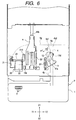
- FIG. 6 is a bottom view showing the disk package being inserted and FIG. 7 is a bottom view showing a completely loaded state of the disk package.
- the disk package P is inserted in X1 direction from the insertion port A1 of the housing A.
- the bottom le of the disk package P and the bottom B1 of the package loading area are in the following relation.
- the generally triangular projection 11d of the lock member 11 comes into abutment with the inclined portion 4a1 as a constituent of the expanded portion 4a shown in FIG. 3.
- the projection 11d then turns in a2 direction along the inclined portion 4a1 in FIG. 4 and goes into such an unlocked state as shown in FIG. 6.
- the projection 11d moves along a guide groove 4 and reaches the associated lock groove 4b. Then, as shown in FIG.
- the lock member 11 is turned in ⁇ 1 direction with the urging force of the urging member S1, so that the projection 11d gets into the lock groove 4b and assumes a locked state.
- the disk package P is locked and the loading thereof into the package loading area B is completed.
- the moving plate 14 Before insertion of the disk package P, as shown in FIG. 4, the moving plate 14 is urged with the urging member S2 and is positioned on the most X2 side indicated at (a) in FIG. 6.
- an edge portion 1g of the case 1 comes into abutment with the receiving portion 14b of the moving plate 14.
- the edge portion 1g pushes the receiving portion 14b to the inner part of the package loading area B, so that the moving plate 14 is moved in X1 direction opposite to the biasing direction of the urging member S2.
- the moving plate 14 In a completely loaded state of the disk package P, the moving plate 14 reaches its position indicated at (b) in FIG. 7.
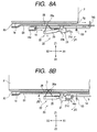
- FIG. 8A is a partial sectional view showing the disk package being inserted and FIG. 8B is a partial sectional view showing a completely loaded state of the disk package.
- the push-up piece 14e also moves in the same direction. As shown in FIGS. 6 and 7, at the position where the push-up piece 14e arrives there is positioned the to-be-pushed-up portion 21d of the rotary member 21 in the contact mechanism portion 20 described above.
- the rotary member 21 is urged and rotates in ⁇ 2 direction under the action of the urging member S3, and the base 25 of the contact support member 22 turns in ⁇ 1 direction.
- the contact 26a is in a stand-by position spaced apart from the wall surface of the disk package P being inserted.
- the to-be-pushed-up portion 21d assumes the state indicated at (c) in which it is close to the bottom B1 (in Z1 direction) of the package loading area B.
- the push-up piece 14e gets in between the bottom B1 and the to-be-pushed-up portion 21d and pushes the to-be-pushed-up portion in Z2 direction.
- connection terminals 3 formed exposedly on the bottom 1e of the disk package are positioned in opposition to the base 25 and the square hole 28. Further, as shown in FIG. 8B, the connection terminals 3 are opposed to the rotated positions of the contacts 26a of the conductors 26. The terminals 3 and contacts 26a come into contact with each other. As noted previously, the conductors 26 are each deformable elastically in Z1 direction through the torsion spring portion 26b and the gap d (see FIG. 5). That is, an electrical connection is ensured by elastic contact of the contacts 26a with the connection terminals 3.
- Ejection of the disk package P is performed in the following manner.
- the package ejection is started by operating an eject button provided in an operating panel of the disk unit or in a remote controller. Once the eject button is pushed, an unlocking lever L shown in FIG. 7 is moved in X2 direction by means of an unlocking mechanism portion (not shown) and pushes the projection 11e of the lock member 11. Consequently, the lock member is turned in ⁇ 2 direction, so that the projection 11d becomes disengaged from the associated lock groove 4d and the disk package P is unlocked.
- the moving plate 14 is moved in X2 direction, so that the receiving portion 14b formed at the front end of the moving plate 14 pushes the edge portion 1g of the case 1 in X2 direction.
- the moving plate 14 moves from the position (b) to the position (a), the disk package P is ejected to the insertion port A1 side.
- the rotating motion of the contact mechanism portion 20 ends immediately before complete loading of the disk package P and the contact 26a comes into abutment with the connection terminal 3 prior to completion of the package loading.
- this can be achieved by forming the push-up piece 14e in a slightly extended shape in X1 direction or by slightly shifting the rotating shaft 24 of the contact mechanism portion 20 toward X2 side, allowing the push-up piece 14e to abut the to-be-pushed-up portion 21d slightly earlier.
- the length of the contact 26a may be made a little longer to increase the degree of projection thereof.
- the contacts 26a slide a very short distance on the connection terminals 3, so that both are rubbed against each other, thereby making the formation of metallic oxide films and stain of the contacts difficult and allowing self-cleaning of the contacts 26a and connection terminals 3 to be carried out.
- the sliding motion permits removal thereof. Therefore, it becomes possible to prevent the occurrence of electrical inconveniences such as contact defect and it becomes possible to make access to the foregoing memory board M in a satisfactory manner. Consequently, it is possible to accurately detect the type of each RAM or ROM disk contained in the disk package as well as index information such as TOC data.
- the disk package can be loaded while allowing cleaning of the lock mechanism and contacts to be done manually, it is possible to omit such drive members as a motor and a solenoid.
- the contacts on the device body side move away from the connection terminals of the package, and when the package has been loaded, the contacts and the connection terminals come into contact with each other. Therefore, at the time of loading and ejection of the package, the contacting force of the contacts does not act as a load. Particularly, where the package is inserted in the longitudinal direction, the contacts do not slide a long distance on the package wall surface and hence there is no fear of the contacts being stained by the package wall surface.
Landscapes
- Coupling Device And Connection With Printed Circuit (AREA)
- Packaging For Recording Disks (AREA)
Applications Claiming Priority (2)
| Application Number | Priority Date | Filing Date | Title |
|---|---|---|---|
| JP9269698A JPH11110893A (ja) | 1997-10-02 | 1997-10-02 | 記録媒体の装着装置 |
| JP269698/97 | 1997-10-02 |
Publications (1)
| Publication Number | Publication Date |
|---|---|
| EP0907172A1 true EP0907172A1 (fr) | 1999-04-07 |
Family
ID=17475950
Family Applications (1)
| Application Number | Title | Priority Date | Filing Date |
|---|---|---|---|
| EP98307899A Withdrawn EP0907172A1 (fr) | 1997-10-02 | 1998-09-29 | Dispositif de chargement de support d' enregistrement |
Country Status (5)
| Country | Link |
|---|---|
| US (1) | US6188663B1 (fr) |
| EP (1) | EP0907172A1 (fr) |
| JP (1) | JPH11110893A (fr) |
| KR (1) | KR100269990B1 (fr) |
| TW (1) | TW389889B (fr) |
Cited By (1)
| Publication number | Priority date | Publication date | Assignee | Title |
|---|---|---|---|---|
| EP1684200A1 (fr) * | 2005-01-21 | 2006-07-26 | Origgio Limited | Appareil pour le téléchargement de données |
Families Citing this family (1)
| Publication number | Priority date | Publication date | Assignee | Title |
|---|---|---|---|---|
| TWI271715B (en) * | 2004-12-02 | 2007-01-21 | Lite On It Corp | Locking apparatus and a method |
Citations (5)
| Publication number | Priority date | Publication date | Assignee | Title |
|---|---|---|---|---|
| US4443049A (en) * | 1978-12-27 | 1984-04-17 | Compagnie Internationale Pour L'informatique Cii-Honeywell Bull (Societe Anonyme) | Connector for portable objects such as credit cards |
| EP0274684A1 (fr) * | 1986-12-12 | 1988-07-20 | Omron Tateisi Electronics Co. | Lecteur de cartes à circuit intégré |
| US4899326A (en) * | 1986-10-15 | 1990-02-06 | Pioneer Electronic Corporation | Magazine-housed disk player |
| WO1990006579A2 (fr) * | 1988-11-30 | 1990-06-14 | Goulven Jean Alain Vernois | Disquette perfectionnee |
| EP0637026A1 (fr) * | 1993-07-30 | 1995-02-01 | Canon Kabushiki Kaisha | Appareil à cassette |
Family Cites Families (5)
| Publication number | Priority date | Publication date | Assignee | Title |
|---|---|---|---|---|
| JP2701269B2 (ja) * | 1987-10-12 | 1998-01-21 | 松下電器産業株式会社 | 光学式マルチディスク再生装置 |
| DE3842702A1 (de) | 1988-12-19 | 1990-06-21 | Boehringer Mannheim Gmbh | Testtraeger zur analytischen untersuchung einer probenfluessigkeit mit hilfe einer spezifischen bindungsreaktion zweier bioaffiner bindungspartner und entsprechendes testverfahren |
| US5281160A (en) * | 1991-11-07 | 1994-01-25 | Burndy Corporation | Zero disengagement force connector with wiping insertion |
| KR0175335B1 (ko) | 1992-08-28 | 1999-04-15 | 구쯔사와 겐다로오 | 디스크 선택식 플레이어 |
| JP3338303B2 (ja) * | 1996-09-25 | 2002-10-28 | アルプス電気株式会社 | ディスクパッケージ |
-
1997
- 1997-10-02 JP JP9269698A patent/JPH11110893A/ja not_active Withdrawn
-
1998
- 1998-09-14 TW TW087115276A patent/TW389889B/zh not_active IP Right Cessation
- 1998-09-23 US US09/159,329 patent/US6188663B1/en not_active Expired - Fee Related
- 1998-09-29 EP EP98307899A patent/EP0907172A1/fr not_active Withdrawn
- 1998-09-30 KR KR1019980040933A patent/KR100269990B1/ko not_active Expired - Fee Related
Patent Citations (5)
| Publication number | Priority date | Publication date | Assignee | Title |
|---|---|---|---|---|
| US4443049A (en) * | 1978-12-27 | 1984-04-17 | Compagnie Internationale Pour L'informatique Cii-Honeywell Bull (Societe Anonyme) | Connector for portable objects such as credit cards |
| US4899326A (en) * | 1986-10-15 | 1990-02-06 | Pioneer Electronic Corporation | Magazine-housed disk player |
| EP0274684A1 (fr) * | 1986-12-12 | 1988-07-20 | Omron Tateisi Electronics Co. | Lecteur de cartes à circuit intégré |
| WO1990006579A2 (fr) * | 1988-11-30 | 1990-06-14 | Goulven Jean Alain Vernois | Disquette perfectionnee |
| EP0637026A1 (fr) * | 1993-07-30 | 1995-02-01 | Canon Kabushiki Kaisha | Appareil à cassette |
Cited By (1)
| Publication number | Priority date | Publication date | Assignee | Title |
|---|---|---|---|---|
| EP1684200A1 (fr) * | 2005-01-21 | 2006-07-26 | Origgio Limited | Appareil pour le téléchargement de données |
Also Published As
| Publication number | Publication date |
|---|---|
| US6188663B1 (en) | 2001-02-13 |
| JPH11110893A (ja) | 1999-04-23 |
| TW389889B (en) | 2000-05-11 |
| KR19990036722A (ko) | 1999-05-25 |
| KR100269990B1 (ko) | 2000-10-16 |
Similar Documents
| Publication | Publication Date | Title |
|---|---|---|
| US6239950B1 (en) | High density flexible disk drive having a large capacity detecting switch provided at a position corresponding to a large capacity identifier hole provided in a case of a large capacity flexible disk | |
| US6480453B2 (en) | Apparatus and method for driving an optical disc with a caddy having a cover | |
| JPS63223891A (ja) | Icカ−ド読取り・書込み装置 | |
| JPWO1997002565A1 (ja) | 記録媒体装置及びこの記憶媒体装置を記録媒体に用いる記録及び/又は再生装置 | |
| CN1218954A (zh) | 用于装载不同规格盘的装置 | |
| JP2960295B2 (ja) | カートリッジ交換機構 | |
| JP3470438B2 (ja) | テープカートリッジのオートローダー | |
| KR100338448B1 (ko) | 내부에기록매체를유지하는다양한치수의카세트및신호기록재생시스템 | |
| US6188663B1 (en) | Recording medium loading device | |
| US20050070142A1 (en) | Storage medium convey apparatus and convey method and recording and/or reproduction apparatus | |
| US6592041B1 (en) | Transfer apparatus and recording and/or reproduction method and transfer method and recording and/or reproduction method | |
| US6570841B1 (en) | Disk cartridge and disk player | |
| US6154423A (en) | Recording medium identifying device | |
| JP4083865B2 (ja) | 車載用ディスク及びテープ再生装置 | |
| CN100356394C (zh) | 用于具有接线端子的记录介质的装载装置 | |
| JP3470439B2 (ja) | テープカートリッジのオートローダー | |
| JPH11312348A (ja) | 記録再生装置 | |
| JP3608963B2 (ja) | マガジン装填式の記録媒体駆動装置 | |
| JP3475550B2 (ja) | テープカートリッジのオートローダー | |
| JP3638804B2 (ja) | マガジン装填式の記録媒体駆動装置 | |
| JP3385777B2 (ja) | テープカートリッジのオートローダー | |
| JP3404963B2 (ja) | テープカートリッジのオートローダー | |
| KR100260926B1 (ko) | 트레이방식자기기록재생기의테이프카세트리드록킹해제장치 | |
| JPH0689482A (ja) | カセット装填装置 | |
| JPH0676453A (ja) | オートチェンジ機能を有する記録媒体の再生装置 |
Legal Events
| Date | Code | Title | Description |
|---|---|---|---|
| PUAI | Public reference made under article 153(3) epc to a published international application that has entered the european phase |
Free format text: ORIGINAL CODE: 0009012 |
|
| AK | Designated contracting states |
Kind code of ref document: A1 Designated state(s): DE FR GB NL |
|
| AX | Request for extension of the european patent |
Free format text: AL;LT;LV;MK;RO;SI |
|
| 17P | Request for examination filed |
Effective date: 19990313 |
|
| AKX | Designation fees paid |
Free format text: DE FR GB NL |
|
| 17Q | First examination report despatched |
Effective date: 20030917 |
|
| GRAP | Despatch of communication of intention to grant a patent |
Free format text: ORIGINAL CODE: EPIDOSNIGR1 |
|
| STAA | Information on the status of an ep patent application or granted ep patent |
Free format text: STATUS: THE APPLICATION IS DEEMED TO BE WITHDRAWN |
|
| 18D | Application deemed to be withdrawn |
Effective date: 20050302 |