EP0907231A1 - Vorrichtung zum Befestigen von elektrischen oder elektronischen Bauteilen - Google Patents
Vorrichtung zum Befestigen von elektrischen oder elektronischen Bauteilen Download PDFInfo
- Publication number
- EP0907231A1 EP0907231A1 EP98117656A EP98117656A EP0907231A1 EP 0907231 A1 EP0907231 A1 EP 0907231A1 EP 98117656 A EP98117656 A EP 98117656A EP 98117656 A EP98117656 A EP 98117656A EP 0907231 A1 EP0907231 A1 EP 0907231A1
- Authority
- EP
- European Patent Office
- Prior art keywords
- wall
- holding part
- wedge
- electrical
- clamping piece
- Prior art date
- Legal status (The legal status is an assumption and is not a legal conclusion. Google has not performed a legal analysis and makes no representation as to the accuracy of the status listed.)
- Granted
Links
- 230000004888 barrier function Effects 0.000 claims description 5
- 238000009434 installation Methods 0.000 claims description 3
- 239000000463 material Substances 0.000 claims description 2
- 239000012528 membrane Substances 0.000 claims description 2
- 230000000284 resting effect Effects 0.000 claims 1
- 239000012780 transparent material Substances 0.000 abstract 1
- 238000010276 construction Methods 0.000 description 2
- 230000001419 dependent effect Effects 0.000 description 1
- 230000000694 effects Effects 0.000 description 1
- 230000035939 shock Effects 0.000 description 1
- 239000004575 stone Substances 0.000 description 1
Images

Classifications
-
- H—ELECTRICITY
- H02—GENERATION; CONVERSION OR DISTRIBUTION OF ELECTRIC POWER
- H02B—BOARDS, SUBSTATIONS OR SWITCHING ARRANGEMENTS FOR THE SUPPLY OR DISTRIBUTION OF ELECTRIC POWER
- H02B1/00—Frameworks, boards, panels, desks, casings; Details of substations or switching arrangements
- H02B1/015—Boards, panels, desks; Parts thereof or accessories therefor
- H02B1/04—Mounting thereon of switches or of other devices in general, the switch or device having, or being without, casing
- H02B1/044—Mounting through openings
-
- H—ELECTRICITY
- H05—ELECTRIC TECHNIQUES NOT OTHERWISE PROVIDED FOR
- H05K—PRINTED CIRCUITS; CASINGS OR CONSTRUCTIONAL DETAILS OF ELECTRIC APPARATUS; MANUFACTURE OF ASSEMBLAGES OF ELECTRICAL COMPONENTS
- H05K7/00—Constructional details common to different types of electric apparatus
- H05K7/02—Arrangements of circuit components or wiring on supporting structure
Definitions
- the present invention relates to a device for fastening electrical or electronic components such. B. from sensors, transmitters or Receivers of light barriers, switches or the like, on the back a wall provided with a bore, for example the wall a door or frame profile.
- Electrical or electronic components such as B. sensors, transmitters or Receivers of light barriers, switches or the like are used in many Use cases on the back of a drilled Wall, for example the wall of a door or frame profile, attached.
- the hole can be used for this, for example Switch buttons or the like from the one on the back of the wall lying electrical or electronic component to the front of the wall to protrude through or simply to send transmitter or receiver on the To place the back of a wall so that through the hole Signals can be sent or received.
- one wall is not one Building walls made of stone or concrete, but exclusively for example a wall of a door or, a switch housing or the like understand, so a comparatively thin wall.
- the present invention has for its object a device Generic type to create, on the one hand by a simple Construction and on the other hand, thanks to a simple installation option difficult or cramped space.
- a holding part and a wedge-shaped clamping piece consisting of a base plate with a Cover flange and an approximately perpendicular to the base plate Holder with means for fixing an electrical or electronic Component exists and the bracket or the base plate with at least one undercut intended for the installation of the wedge-shaped clamping piece is provided so that the holding part with its cover flange on the Front of a wall through that on the back of the wall adjacent wedge-shaped clamping piece can be clamped to the wall.
- the device according to the invention consists of two comparatively simple producible components, namely a holding part and a wedge-shaped Clamp.
- the holding part with its provided with a cover flange for the hole Base plate and the connected, approximately perpendicular to the base plate running bracket is through the bore of a wall put through and on the back of the wall can now fixed electrical or electronic component fixed by the bracket become.
- the wedge-shaped clamping piece is then used to fix the whole slid on under the back of the wall and this will Holding part with its cover flange on the front of one Wall through that on the back of the wall and on the Undercut wedge-shaped clamping piece clamped to the wall.
- This assembly is extremely easy to perform and also comparatively confined space or space available. Specific Tools are not required as there are no screw connections or similar Fastening types are used.
- reference number 1 denotes a wall, for example the wall of a door or frame profile, referred to Back 1a an electrical or electronic component, which with the Reference number 2 is designated.
- the exemplary embodiment is the electrical or electronic Component around a transmitter or a receiver of a light barrier.
- the electrical or electronic component 2 with a lens 3 equipped with which a signal can be transmitted or received.
- the holding part 4 consists essentially of a with a cover flange 6 provided base plate 7 and one approximately perpendicular to the base plate 7 extending bracket 8, which means for fixing the to be fixed has electrical or electronic component 2.
- the bracket 8 consists of an approximately U-shaped Clip, with the two clip legs at their free ends with Locking hooks 9 are equipped, which are the electrical or to be fixed reach behind electronic component 2.
- the wall 1 is provided with a bore 10, the diameter of which is the same or larger than the largest diameter of the base plate 7. By this Bore 10, the holding part 8 can be inserted through the wall 1 become.
- the cover flange 6 is covered by the edge areas of the Bore 10 on the front 1b of the wall 1 on this wall.
- the electrical or electronic structure to be specified is then in the clip-like construction of the holding part 8 snapped in, as in FIG. 2 shown. It can be ensured by constructive means that a latching or fixing of the electrical or electronic component 2 on the holding part 8 is only possible in such a position in which the lens 3 or another functional part, in alignment with the bore 10 of the wall 1 lies.
- the two legs of the bracket 8, which are electrical or electronic Reaching around component 2 laterally are each provided with undercuts 11. These undercuts 11 serve to design the wedge-shaped To record side legs 13 of the clamping piece 5.
- the clamping piece 5 is on the back 1a of the wall 1 and, as already mentioned, engages behind the Undercuts 11 of the bracket 8.
- the wedge effect Cover flange 6 firmly tightened to the front 1b of the wall 1. In order to the electrical or electronic component 2 is safe in the area of its intended use location against the wall.
- the undercuts 11 are provided with a toothing 12, as arranged in Figure 3.
- the electrical or electronic component 2 to the transmitter or Receiver of a light barrier with a lens 3.
- the holding part 4 at least in that Lens 3 opposite area consists of translucent material.
- the holding part 4 does not need to be broken.
- an electrical or electronic Component mounted which for example from the front 1b of the wall 1st is provided with a switch button to be operated, the holding part 4 be perforated concentrically to the bore 10 so that operation is possible is.
- a membrane can also be used in the area mentioned be arranged, which enables the operation of a switch.
- the bracket 8 for fixing the electrical or electronic component designed like a clamp.
- the holder 8 also consist of a pin provided with locking means, through a corresponding opening of the electrical or electronic Component 2 passes through or protrudes into a corresponding hole, sort of like a snap fastener.
- both the holding part 4 and the wedge-shaped one Clamping piece 5 made in one piece from a plastic.
Landscapes
- Engineering & Computer Science (AREA)
- Microelectronics & Electronic Packaging (AREA)
- Power Engineering (AREA)
- Casings For Electric Apparatus (AREA)
- Fixed Capacitors And Capacitor Manufacturing Machines (AREA)
- Measuring Fluid Pressure (AREA)
Abstract
Description
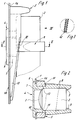
- Figur 1
- einen Längsschnitt durch eine Wandung, an deren Rückseite ein elektrisches oder elektronisches Bauteil mittels einer erfindungsgemäßen Vorrichtung festgelegt ist,
- Figur 2
- einen Schnitt nach der Linie II-II in Figur 1,
- Figur
- 3 die in Figur 1 mit III bezeichnete Einzelheit in vergrößerter Darstellung,
- Figur 4
- eine Ansicht in Richtung des Pfeiles IV in Figur 1.
Claims (7)
- Vorrichtung zum Befestigen von elektrischen oder elektronischen Bauteilen wie z. B. von Sensoren, Sendern oder Empfängern von Lichtschranken, Schaltern oder dergleichen an der Rücksetie einer mit einer Bohrung versehenen Wandung, beispielsweise der Wandung eines Tür- oder Blendrahmenprofiles, gekennzeichnet durch ein Halteteil (4) und ein keilförmiges Klemmstück (5), wobei das Halteteil (4) aus einer Grundplatte (7) mit einem Abdeckflansch (6) sowie einer sich etwa lotrecht zur Grundplatte (7) mit einem Abdeckflansch (6) sowie einer sich etwa lotrecht zur Grundplatte (7) erstreckenden Halterung (8) mit Mitteln zur Fixierung eines elektrischen oder elektronischen Bauteiles besteht und daß die Halterung (8) oder die Grundplatte (7) mit mindestens einer für die Anlage des keilförmigen Klemmstückes (5) bestimmten Hinterschneidung (11) versehen ist, so daß das Halteteil (4) unter Anlage seines Abdeckflansches (6) an der Vorderseite an einer Wandung durch das auf der Rückseite der Wandung anliegende keilförmige Klemmstück (5) an der Wandung festklemmbar ist.
- Vorrichtung nach Anspruch 1, dadurch gekennzeichnet, daß das Halteteil (4) in seinem mittleren, im montierten Zustand etwa konzentrisch zur Bohrung (10) liegenden Bereich aus einem lichtdurchlässigen Material besteht.
- Vorrichtung nach Anspruch 1, dadurch gekennzeichnet, daß das Halteteil (4) in seinem mittleren, im montierten Zustand etwa konzentrisch zur Bohrung (10) liegenden Bereich mit einer Membran oder dergleichen ausgestattet ist.
- Vorrichtung nach Anspruch 1, dadurch gekennzeichnet, daß das Halteteil (4) in seinem mittleren, konzentrisch zur Bohrung (10) liegenden Bereich mit einer Durchbrechung ausgestattet ist.
- Vorrichtung nach einem oder mehreren der vorhergehenden Ansprüche, dadurch gekennzeichnet, daß die Halterung (8) etwa klammerförmig ausgebildet und mit zwei das festzulegende elektrische oder elektronische Bauteil (2) seitlich umgreifenden Schenkeln besteht, die an ihren freien Enden das elektrische oder elektronische Bauteil (2) hintergreifende Rasthaken (9) aufweisen.
- Vorrichtung nach einem oder mehreren der vorhergehenden Ansprüche, dadurch gekennzeichnet, daß die aneinanderliegenden Flanken der Hinterschneidungen (11) einerseits und des keilförmigen Klemmstückes (5) andererseits mit einer Verzahnung (12) ausgestattet sind.
- Vorrichtung nach einem oder mehreren der vorhergehenden Ansprüche, dadurch gekennzeichnet, daß das Halteteil (4) und das keilförmige Klemmstück (5) aus Kunststoff hergestellt sind.
Applications Claiming Priority (2)
| Application Number | Priority Date | Filing Date | Title |
|---|---|---|---|
| DE29717609U | 1997-10-02 | ||
| DE29717609U DE29717609U1 (de) | 1997-10-02 | 1997-10-02 | Vorrichtung zum Befestigen von elektrischen oder elektronischen Bauteilen |
Publications (2)
| Publication Number | Publication Date |
|---|---|
| EP0907231A1 true EP0907231A1 (de) | 1999-04-07 |
| EP0907231B1 EP0907231B1 (de) | 2001-10-17 |
Family
ID=8046768
Family Applications (1)
| Application Number | Title | Priority Date | Filing Date |
|---|---|---|---|
| EP98117656A Expired - Lifetime EP0907231B1 (de) | 1997-10-02 | 1998-09-17 | Vorrichtung zum Befestigen von elektrischen oder elektronischen Bauteilen |
Country Status (4)
| Country | Link |
|---|---|
| EP (1) | EP0907231B1 (de) |
| DE (2) | DE29717609U1 (de) |
| DK (1) | DK0907231T3 (de) |
| ES (1) | ES2165120T3 (de) |
Cited By (1)
| Publication number | Priority date | Publication date | Assignee | Title |
|---|---|---|---|---|
| CN105129397A (zh) * | 2015-09-16 | 2015-12-09 | 成都智齐科技有限公司 | 芯片驱动定位机构 |
Families Citing this family (3)
| Publication number | Priority date | Publication date | Assignee | Title |
|---|---|---|---|---|
| DE19833090A1 (de) * | 1998-07-23 | 2000-05-25 | Moeller Gmbh | Befehls- und/oder Meldegerät |
| DE19853918C1 (de) * | 1998-11-23 | 2001-01-18 | Vipa Ges Fuer Visualisierung U | Befestigungsvorrichtung für ein elektronisches Gerät oder dessen Tragrahmen in einem Frontplatten-Ausschnitt |
| DE102006008796B3 (de) * | 2006-02-24 | 2007-12-27 | Interactive Wear Ag | Fixiervorrichtung mit integrierter Elektronikkomponente |
Citations (4)
| Publication number | Priority date | Publication date | Assignee | Title |
|---|---|---|---|---|
| DE3418845A1 (de) * | 1984-05-21 | 1985-11-21 | Siemens AG, 1000 Berlin und 8000 München | Befehlsschalter |
| US4939406A (en) * | 1987-12-16 | 1990-07-03 | Mannesmann Kienzle Gmbh | Arrangement for fastening a housing |
| WO1994018731A1 (de) * | 1993-02-09 | 1994-08-18 | Siemens Aktiengesellschaft | Befehls- und/oder meldegerät |
| EP0777308A1 (de) * | 1995-12-01 | 1997-06-04 | GRUNDIG E.M.V. Elektro-Mechanische Versuchsanstalt Max Grundig & Co. KG. | Vorrichtung zur Befestigung von Näherungsinitiatoren an Transportsystemen |
-
1997
- 1997-10-02 DE DE29717609U patent/DE29717609U1/de not_active Expired - Lifetime
-
1998
- 1998-09-17 DE DE59802043T patent/DE59802043D1/de not_active Expired - Fee Related
- 1998-09-17 EP EP98117656A patent/EP0907231B1/de not_active Expired - Lifetime
- 1998-09-17 DK DK98117656T patent/DK0907231T3/da active
- 1998-09-17 ES ES98117656T patent/ES2165120T3/es not_active Expired - Lifetime
Patent Citations (4)
| Publication number | Priority date | Publication date | Assignee | Title |
|---|---|---|---|---|
| DE3418845A1 (de) * | 1984-05-21 | 1985-11-21 | Siemens AG, 1000 Berlin und 8000 München | Befehlsschalter |
| US4939406A (en) * | 1987-12-16 | 1990-07-03 | Mannesmann Kienzle Gmbh | Arrangement for fastening a housing |
| WO1994018731A1 (de) * | 1993-02-09 | 1994-08-18 | Siemens Aktiengesellschaft | Befehls- und/oder meldegerät |
| EP0777308A1 (de) * | 1995-12-01 | 1997-06-04 | GRUNDIG E.M.V. Elektro-Mechanische Versuchsanstalt Max Grundig & Co. KG. | Vorrichtung zur Befestigung von Näherungsinitiatoren an Transportsystemen |
Cited By (1)
| Publication number | Priority date | Publication date | Assignee | Title |
|---|---|---|---|---|
| CN105129397A (zh) * | 2015-09-16 | 2015-12-09 | 成都智齐科技有限公司 | 芯片驱动定位机构 |
Also Published As
| Publication number | Publication date |
|---|---|
| DK0907231T3 (da) | 2002-01-28 |
| DE59802043D1 (de) | 2001-12-13 |
| DE29717609U1 (de) | 1997-11-13 |
| ES2165120T3 (es) | 2002-03-01 |
| EP0907231B1 (de) | 2001-10-17 |
Similar Documents
| Publication | Publication Date | Title |
|---|---|---|
| DE19806690A1 (de) | Befestigung eines Bauteiles an einem plattenförmigen Tragteil | |
| DE19717027A1 (de) | Verschraubung einer Scharnierlasche für Fahrzeugtüren | |
| DE29806503U1 (de) | Haltevorrichtung für ein Seitenaufprall-Gassackmodul für Kraftfahrzeuge | |
| EP0907231B1 (de) | Vorrichtung zum Befestigen von elektrischen oder elektronischen Bauteilen | |
| DE202006003313U1 (de) | Lichtschrankengehäuse, Lichtschrankenelement und Torvorrichtungen | |
| DE4012253C1 (en) | Control magnet carrier - has U=shaped bin with bridge port having attachment for fixing to lock plate and two shanks | |
| DE102009052761B4 (de) | Befestigungssystem für eine Führungsschiene eines Fensterhebers | |
| DE10050098B4 (de) | Sicherheitsmodul | |
| DE29917214U1 (de) | Vorrichtung zum Ausrichten von zwei benachbarten, nacheinander an einem Fahrzeug zu befestigenden Teilen | |
| EP1686232A2 (de) | Lichtschrankenhalterung | |
| DE19809414B4 (de) | Zusatzbremsleuchte für ein Kraftfahrzeug | |
| EP1371530B1 (de) | Befestigungseinrichtung | |
| DE9016393U1 (de) | Vorrichtung zum Verbinden mehrerer Teile | |
| AT7368U1 (de) | Beschlag | |
| EP2477048B1 (de) | Lichtgittergehäuse | |
| DE102004004851A1 (de) | Sensorbefestigung | |
| DE19501455A1 (de) | Anordnung zur Befestigung eines ersten an einem zweiten Bauteil, insbesondere eines Wärmeabschirmbleches am Bodenblech eines Kraftfahrzeuges | |
| DE202006015143U1 (de) | Trägerbaueinheit zum Befestigen einer Kraftfahrzeug-Türschlosseinheit an einem Trägerteil einer Kraftfahrzeugtür | |
| DE29519800U1 (de) | Riegelverbindung für Leuchten | |
| EP1037351A1 (de) | Halterahmen zur Festlegung eines Bauteils an einer Wand | |
| EP1648066B1 (de) | Aufputzmontagevorrichtung | |
| DE10306783B4 (de) | Lösbare Befestigungsvorrichtung für ein elektronisches Modul | |
| DE102005026842B4 (de) | Befestigungseinrichtung für ein in eine Öffnung einsetzbares Bauteil | |
| EP1635435B1 (de) | Elektrische/elektronische Installationseinheit | |
| DE102009049749B4 (de) | Heizkostenverteiler |
Legal Events
| Date | Code | Title | Description |
|---|---|---|---|
| PUAI | Public reference made under article 153(3) epc to a published international application that has entered the european phase |
Free format text: ORIGINAL CODE: 0009012 |
|
| AK | Designated contracting states |
Kind code of ref document: A1 Designated state(s): BE CH DK ES FR GB IT LI NL SE |
|
| AX | Request for extension of the european patent |
Free format text: AL;LT;LV;MK;RO;SI |
|
| 17P | Request for examination filed |
Effective date: 19990930 |
|
| AKX | Designation fees paid |
Free format text: DE |
|
| RBV | Designated contracting states (corrected) |
Designated state(s): BE CH DK ES FR GB IT LI NL SE |
|
| REG | Reference to a national code |
Ref country code: DE Ref legal event code: 8566 |
|
| GRAG | Despatch of communication of intention to grant |
Free format text: ORIGINAL CODE: EPIDOS AGRA |
|
| GRAG | Despatch of communication of intention to grant |
Free format text: ORIGINAL CODE: EPIDOS AGRA |
|
| GRAH | Despatch of communication of intention to grant a patent |
Free format text: ORIGINAL CODE: EPIDOS IGRA |
|
| 17Q | First examination report despatched |
Effective date: 20010208 |
|
| GRAH | Despatch of communication of intention to grant a patent |
Free format text: ORIGINAL CODE: EPIDOS IGRA |
|
| GRAA | (expected) grant |
Free format text: ORIGINAL CODE: 0009210 |
|
| AK | Designated contracting states |
Kind code of ref document: B1 Designated state(s): BE CH DE DK ES FR GB IT LI NL SE |
|
| RBV | Designated contracting states (corrected) |
Designated state(s): BE CH DE DK ES FR GB IT LI NL SE |
|
| REG | Reference to a national code |
Ref country code: CH Ref legal event code: NV Representative=s name: ISLER & PEDRAZZINI AG Ref country code: CH Ref legal event code: EP |
|
| RAP2 | Party data changed (patent owner data changed or rights of a patent transferred) |
Owner name: BERNSTEIN AG |
|
| REG | Reference to a national code |
Ref country code: DE Ref legal event code: 8570 |
|
| REF | Corresponds to: |
Ref document number: 59802043 Country of ref document: DE Date of ref document: 20011213 |
|
| REG | Reference to a national code |
Ref country code: GB Ref legal event code: IF02 |
|
| GBT | Gb: translation of ep patent filed (gb section 77(6)(a)/1977) |
Effective date: 20011204 |
|
| NLT2 | Nl: modifications (of names), taken from the european patent patent bulletin |
Owner name: BERNSTEIN AG |
|
| REG | Reference to a national code |
Ref country code: DK Ref legal event code: T3 |
|
| REG | Reference to a national code |
Ref country code: ES Ref legal event code: FG2A Ref document number: 2165120 Country of ref document: ES Kind code of ref document: T3 |
|
| ET | Fr: translation filed | ||
| PLBE | No opposition filed within time limit |
Free format text: ORIGINAL CODE: 0009261 |
|
| STAA | Information on the status of an ep patent application or granted ep patent |
Free format text: STATUS: NO OPPOSITION FILED WITHIN TIME LIMIT |
|
| 26N | No opposition filed | ||
| PGFP | Annual fee paid to national office [announced via postgrant information from national office to epo] |
Ref country code: GB Payment date: 20030826 Year of fee payment: 6 |
|
| PGFP | Annual fee paid to national office [announced via postgrant information from national office to epo] |
Ref country code: NL Payment date: 20030917 Year of fee payment: 6 |
|
| PGFP | Annual fee paid to national office [announced via postgrant information from national office to epo] |
Ref country code: FR Payment date: 20030918 Year of fee payment: 6 |
|
| PGFP | Annual fee paid to national office [announced via postgrant information from national office to epo] |
Ref country code: BE Payment date: 20030922 Year of fee payment: 6 |
|
| PGFP | Annual fee paid to national office [announced via postgrant information from national office to epo] |
Ref country code: CH Payment date: 20030923 Year of fee payment: 6 Ref country code: SE Payment date: 20030923 Year of fee payment: 6 |
|
| PGFP | Annual fee paid to national office [announced via postgrant information from national office to epo] |
Ref country code: ES Payment date: 20030924 Year of fee payment: 6 |
|
| PGFP | Annual fee paid to national office [announced via postgrant information from national office to epo] |
Ref country code: DK Payment date: 20030925 Year of fee payment: 6 |
|
| PG25 | Lapsed in a contracting state [announced via postgrant information from national office to epo] |
Ref country code: GB Free format text: LAPSE BECAUSE OF NON-PAYMENT OF DUE FEES Effective date: 20040917 |
|
| PG25 | Lapsed in a contracting state [announced via postgrant information from national office to epo] |
Ref country code: SE Free format text: LAPSE BECAUSE OF NON-PAYMENT OF DUE FEES Effective date: 20040918 Ref country code: ES Free format text: LAPSE BECAUSE OF NON-PAYMENT OF DUE FEES Effective date: 20040918 |
|
| PG25 | Lapsed in a contracting state [announced via postgrant information from national office to epo] |
Ref country code: LI Free format text: LAPSE BECAUSE OF NON-PAYMENT OF DUE FEES Effective date: 20040930 Ref country code: DK Free format text: LAPSE BECAUSE OF NON-PAYMENT OF DUE FEES Effective date: 20040930 Ref country code: CH Free format text: LAPSE BECAUSE OF NON-PAYMENT OF DUE FEES Effective date: 20040930 Ref country code: BE Free format text: LAPSE BECAUSE OF NON-PAYMENT OF DUE FEES Effective date: 20040930 |
|
| BERE | Be: lapsed |
Owner name: *BERNSTEIN A.G. Effective date: 20040930 |
|
| PG25 | Lapsed in a contracting state [announced via postgrant information from national office to epo] |
Ref country code: NL Free format text: LAPSE BECAUSE OF NON-PAYMENT OF DUE FEES Effective date: 20050401 |
|
| EUG | Se: european patent has lapsed | ||
| GBPC | Gb: european patent ceased through non-payment of renewal fee |
Effective date: 20040917 |
|
| REG | Reference to a national code |
Ref country code: CH Ref legal event code: PL |
|
| PG25 | Lapsed in a contracting state [announced via postgrant information from national office to epo] |
Ref country code: FR Free format text: LAPSE BECAUSE OF NON-PAYMENT OF DUE FEES Effective date: 20050531 |
|
| NLV4 | Nl: lapsed or anulled due to non-payment of the annual fee |
Effective date: 20050401 |
|
| REG | Reference to a national code |
Ref country code: DK Ref legal event code: EBP |
|
| REG | Reference to a national code |
Ref country code: FR Ref legal event code: ST |
|
| PG25 | Lapsed in a contracting state [announced via postgrant information from national office to epo] |
Ref country code: IT Free format text: LAPSE BECAUSE OF NON-PAYMENT OF DUE FEES Effective date: 20050917 |
|
| REG | Reference to a national code |
Ref country code: ES Ref legal event code: FD2A Effective date: 20040918 |
|
| REG | Reference to a national code |
Ref country code: HK Ref legal event code: WD Ref document number: 1019268 Country of ref document: HK |
|
| PGFP | Annual fee paid to national office [announced via postgrant information from national office to epo] |
Ref country code: DE Payment date: 20061019 Year of fee payment: 9 |
|
| BERE | Be: lapsed |
Owner name: *BERNSTEIN A.G. Effective date: 20040930 |
|
| PG25 | Lapsed in a contracting state [announced via postgrant information from national office to epo] |
Ref country code: DE Free format text: LAPSE BECAUSE OF NON-PAYMENT OF DUE FEES Effective date: 20080401 |