EP0907235A1 - Verfahren zur Herstellung einer lamellierten elektrischen Maschine - Google Patents
Verfahren zur Herstellung einer lamellierten elektrischen Maschine Download PDFInfo
- Publication number
- EP0907235A1 EP0907235A1 EP98117784A EP98117784A EP0907235A1 EP 0907235 A1 EP0907235 A1 EP 0907235A1 EP 98117784 A EP98117784 A EP 98117784A EP 98117784 A EP98117784 A EP 98117784A EP 0907235 A1 EP0907235 A1 EP 0907235A1
- Authority
- EP
- European Patent Office
- Prior art keywords
- stator
- laminations
- rotor
- sheet metal
- electrical machine
- Prior art date
- Legal status (The legal status is an assumption and is not a legal conclusion. Google has not performed a legal analysis and makes no representation as to the accuracy of the status listed.)
- Ceased
Links
Images



Classifications
-
- H—ELECTRICITY
- H02—GENERATION; CONVERSION OR DISTRIBUTION OF ELECTRIC POWER
- H02K—DYNAMO-ELECTRIC MACHINES
- H02K15/00—Processes or apparatus specially adapted for manufacturing, assembling, maintaining or repairing of dynamo-electric machines
- H02K15/02—Processes or apparatus specially adapted for manufacturing, assembling, maintaining or repairing of dynamo-electric machines of stator or rotor bodies
- H02K15/021—Magnetic cores
Definitions
- the invention relates to a method of manufacture a laminated electrical machine, especially one stator-excited motor generator operating according to the reluctance principle; such an electrical machine is e.g. known from EP 0 103 821 B1.
- the engine generators provided form those of Crankshaft of the internal combustion engine can be engaged or disengaged Flywheel mass at the same time the windingless, according to the reluctance principle working rotor of the motor generator.
- the radial The rotor interior is used as a space for further mechanical Components, in particular a coupling for coupling the Flywheel rotor to the crankshaft of the internal combustion engine, keep clear.
- the ring-shaped rotor structure must be electromagnetic and strength-related reasons for themselves closed annular sheet metal lamellae be.
- Such heteropolar excited medium-frequency machines have for stator excitation or heteropolar stator-excited synchronous machines several field windings distributed around the stator circumference on; the stator is advantageously of sector stator design executable, the distributed over the scope Sector stators are not mutually mechanical or magnetic must be connected so that the gaps for the drive side mechanical components are available. That with Grooves for receiving a working winding stator package is just like the rotor, preferably stamped, Sheet metal fins assembled.
- the manufacturing and assembly costs for producing a previously described heteropolar excited medium frequency machine or a previously described heteropolar stator-excited synchronous machine when the drive is fully operational can be significantly reduced.
- the solution to this task succeeds by a method according to claim 1; beneficial Refinements are the subject of the dependent claims.
- a particularly optimal one Material utilization is according to an embodiment of the invention given that for an electrical machine with over distributed the size of sector stators of different sizes each ring-shaped rotor lamella from their inner punching waste Stator laminations of the first type with a larger yoke height and / or larger number of stator teeth and stator laminations second type with a smaller yoke height and / or a smaller number are punched out by stator teeth, being in their mutual Placement in the sheet metal part to be punched at advantageous at least partially common stamping contour of the stator laminations first type radially outside to the stator laminations second type arranged within the annular lamella and the stator laminations of the first type are the stator laminations overlap the second type tangentially.
- stator-excited motor generator works according to the reluctance principle with a closed ring around the circumference axially stacked rotor laminations 3 formed Rotor package and with four over its circumference in the air gap distance distribute, also axially one behind the other layered stator laminations 1 or 2 formed sector stators.
- the installation space in the radially inner area of the rotor laminations 3 is particularly for receiving a clutch provided by means of which the rotor in certain operating states separable from the crankshaft of the internal combustion engine is.
- the circumferential magnetic as well as constructive from each other independent sector stators are in the exemplary embodiment 1 divided into those with stator laminations 1 first type with a larger yoke height H1 and / or larger Number of stator teeth 1.1 and 2 in stator laminations Kind with smaller yoke height H2 and / or small number of Stator teeth 2.1.
- the between the stator teeth 1.1 and 2.2 Remaining grooves are used in a manner known per se Inclusion of one here because of the clearer presentation of the Work winding essential to the invention, not shown.
- each stator lamination has 1 or 2 a tangentially central exciter receiving part 1.2; 2.2; 2.3 on that of FIG 4.5 of an excitation winding 6 or 7 is wrapped, or according to FIG 6, a permanent magnet 8 records.
- the excitation winding 6 or 7 or the permanent magnet 8 becomes a magnetic one in the respective sector stator Flow generated in the tangential direction of the arrow, which then radially across the air gap and then tangential again runs through the rotor; this forms the stator teeth on one tangential side of the field winding magnetic north poles and on the other tangential side the excitation winding magnetic south poles.
- Torque generation takes place according to the known reluctance principle, for which purpose the rotor laminations 3 distributed over the circumference Reluctance teeth 3.1 are provided by intermediate punched out reluctance recesses 3.2 in a simple manner be formed.
- the stator laminations are 1 first type in terms of number and extent the stator teeth 1.1 in the sense of a fourfold pole pitch and the stator laminations 2 of the second kind in the sense of a double pole pitch.
- the two-strand shown here Is by a symmetrical distribution of the machine Stator teeth on both tangential sides of the exciter receiving part characterized, where the number of stator teeth Is a multiple of four.
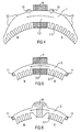
- FIG 2,3 show the optimal according to the invention Material use advantageous mutual training and Arrangement of the punching process in one, possibly multi-stroke from a sheet metal strip 9 punchable stator laminations 1; 2 and rotor laminations 3 for a machine structure according to FIG 1.
- FIG 2 shows stator laminations 1; 2 for receiving a electromagnetic excitation according to FIG. 4.5.
- 3 shows Stator laminations 1; 2 for permanent magnetic stator excitation by a permanent magnet 8 according to FIG. 6.
- the punching waste gussets radially above the rotor plate lamella 3 additionally punched out rotor sheet metal disk sectors 4.5, which can be assembled into closed ring lamellae according to FIG. 7,8 are.
- additional rotor laminations are preferred used for the axial extension of the rotor laminated core, if e.g. a larger axial play of the rotor relative must be accepted to the stator and still the torque power should not be reduced.
- the rotor laminated disk sectors 5, as can be seen from FIG. 5, also provided with reluctance teeth 5.1 by appropriate interposed punched reluctance recesses 5.2 are formed.
- the axial length of the rotor in particular by annular Enlarge rotor laminations, which are made of toothless Rotor-laminated sectors 4 according to FIG 8 assembled are.
- annular Enlarge rotor laminations which are made of toothless Rotor-laminated sectors 4 according to FIG 8 assembled are.
- multi-stroke punching process can be provided in which e.g. first the grooves and then another Stroke advance of the punching tool of gusset-like stamped contours and afterwards Separation or cutouts of the individual stator or rotor laminations respectively.
- Stamped free cutting holes 12 serving for free cutting are indicated, after punching out and layering the metal plates to a rotor package or a sector stator package in advantageously for receiving a surface-flush Weld seam can serve with the sheet metal fins are held together in packages; for an alternative or simultaneous cohesion are rivet holes 13 punched out.
- Brush cut holes 12 or rivet holes 13 are expedient each tangentially in the middle under the reluctance teeth 3.1 arranged. Further punched holes serve as fastening openings 10.11 to hold the sector stators in their engine-side intake; these mounting holes 10, 11 are preferably in sector zones through which equal field flows or in magnetically unloaded sector zones.
Landscapes
- Engineering & Computer Science (AREA)
- Manufacturing & Machinery (AREA)
- Power Engineering (AREA)
- Manufacture Of Motors, Generators (AREA)
- Iron Core Of Rotating Electric Machines (AREA)
Abstract
Description
- FIG 1
- eine axial stirnseitige Draufsicht auf ein ringförmiges Reluktanz-Rotorpaket mit vier über dessen Außenumfang verteilten, noch unbewickelten Sektorstator-Paketen;
- FIG 2
- ein Blechband mit den Stanzkonturen für die eine Hälfte einer ringförmigen Rotor-Blechlamelle und für je eine elektromagnetisch erregbare Stator-Blechlamelle eines größeren und eines kleineren Sektorstators;
- FIG 3
- ein Blechband mit den Stanzkonturen für die eine Hälfte einer ringförmigen Rotor-Blechlamelle und für je eine dauermagnetisch erregbare Stator-Blechlamelle eines größeren und eines kleineren Sektorstators;
- FIG 4
- eine axial stirnseitige Draufsicht auf einen größeren Sektorstator mit einer Erregerwicklung;
- FIG 5
- eine axial stirnseitige Draufsicht auf einen kleineren Sektorstator mit einer Erregerwicklung;
- FIG 6
- eine axial stirnseitige Draufsicht auf einen kleineren Sektorstator mit einem Dauermagneten;
- FIG 7
- eine ringförmige, aus Rotor-Blechlamellensektoren zusammengesetzte Rotor-Blechlamelle mit umfangsseitigen Reluktanz-Ausnehmungen;
- FIG 8
- eine ringförmige, aus Rotor-Blechlamellensektoren zusammengesetzte Rotor-Blechlamelle ohne umfangsseitige Reluktanz-Ausnehmungen.
- 1
- Stator-Blechlamellen erster Art
- 1.1
- Statorzähne
- 2
- Stator-Blechlamellen zweiter Art
- 2.1
- Statorzähne
- 2.2;2.3
- Erreger-Aufnahmeteil
- 3
- Rotor-Blechlamellen
- 3.1
- Reluktanz-Zähne
- 3.2
- Reluktanz-Ausnehmungen
- 4
- Rotor-Blechlamellensektor
- 5
- Rotor-Blechlamellensektor
- 5.1
- Reluktanz-Zähne
- 5.2
- Reluktanz-Ausnehmungen
- 6;7
- Erregerwicklung
- 8
- Dauermagnet
- 9
- Blechband
- 10;11
- Befestigungs-Öffnungen
- 12
- Freischneid-Löcher
- 13
- Nietlöcher
- H1;H2
- Jochhöhe
Claims (10)
- Verfahren zur Herstellung einer lamellierten elektrischen Maschine, insbesondere eines nach dem Reluktanz-Prinzip arbeitenden statorerregten Motor-Generators,mit rinförmigem, aus Rotor-Blechlamellen (3) geschichtetem Rotor, insbesondere Schwungmassen-Rotor;mit zumindest einem aus Stator-Blechlamellen (1;2) geschichteten Sektorstator;mit aus jeweils den gleichen Blechteilen, insbesondere einem Blechband (9) bzw. einer Blechtafel, gestanzten Rotor-Blechlamellen (3) und Stator-Blechlamellen (1;2);mit jeweils ringförmig gestanzten Rotor-Blechlamellen (3) und aus dem innerhalb der ringförmigen Rotor-Blechlamellen (3) verbleibenden Stanzabfall eines Blechteils, insbesondere eines Blechbandes (9), gestanzten Stator-Blechlamellen (1;2).
- Verfahren zur Herstellung einer lamellierten elektrischen Maschine nach dem vorhergehenden Anspruchmit jeweils in einem gemeinsamen, insbesondere mehrhubigen, Stanzvorgang aus einem Blechteil, insbesondere einem Blechband (9) bzw. einer Blechtafel, gestanzten Rotor-Blechlamellen (3) und Stator-Blechlamellen (1;2).
- Verfahren zur Herstellung einer lamellierten elektrischen Maschine, insbesondere mit vier über den Umfang verteilten Sektorstatoren, nach zumindest einem der vorhergehenden Ansprüchemit je ringförmiger Rotorlamelle (3) aus deren innerem Stanzabfall gestanzten, insbesondere zwei, Stator-Blechlamellen (1) erster Art mit größerer Jochhöhe (H1) und/ oder größerer Zahl von Statorzähnen (1.1) und zwei Stator-Blechlamellen (2) zweiter Art mit kleinerer Jochhöhe (H2) und/oder kleinerer Zahl von Statorzähnen (2.1).
- Verfahren zur Herstellung einer lamellierten elektrischen Maschine nach zumindest einem der vorhergehenden Ansprüchemit Stator-Blechlamellen (1;2) mit jeweils einem tangential mittigen Erreger-Aufnahmeteil (1.2;2.2;2.3) und jeweils tangential beidseitigen Statorzahnteilen mit jeweils je Sektorstator tangential beidseitig gleicher Zahl von Statorzähnen (1.1;2.1).
- Verfahren zur Herstellung einer lamellierten elektrischen Maschine nach den vorhergehenden Ansprüchen 3 und/oder 4mit Stator-Blechlamellen (1) erster Art mit größerer Jochhöhe (H1) und/oder Zahl von Statorzähnen (1.1) im Sinne einer vierfachen Polteilung;mit Stator-Blechlamellen (2) zweiter Art mit geringerer Jochhöhe (H2) und/oder Zahl von Statorzähnen (2.1) im Sinne einer zweifachen Polteilung.
- Verfahren zur Herstellung einer lamellierten elektrischen Maschine nach zumindest einem der vorhergehenden Ansprüchemit im Sinne zumindest über Teilbereiche gemeinsamer Stanz-Trennschnitte der in dem Blechteil angeordneten Stator-Blechlamellen (1;2) bzw. Rotor-Blechlamellen (3).
- Verfahren zur Herstellung einer lamellierten elektrischen Maschine nach zumindest einem der vorhergehenden Ansprüchemit aus dem Stanzabfall radial außerhalb der ringförmigen Rotor-Blechlamellen (3) ausgestanzten teilringförmigen Rotor-Blechlamellensektoren (4 bzw.5), die im Sinne einer axial endseitigen Verlängerung des Rotor-Blechpakets vollringförmig zusammenfügbar sind.
- Verfahren zur Herstellung einer lamellierten elektrischen Maschine nach dem vorhergehenden Anspruchmit gleich den übrigen Rotor-Blechlamellen (3) mit Reluktanz-Ausnehmungen (5.2) bzw. Reluktanz-Zähnen 5.1 versehenen Rotor-Blechlamellensektoren (5).
- Verfahren zur Herstellung einer lamellierten elektrischen Maschine nach dem vorhergehenden Anspruch 7mit ungleich den übrigen Rotor-Blechlamellen (3) von Reluktanz-Ausnehmungen (5.2) bzw. Reluktanz-Zähnen 5.1 freien Rotor-Blechlamellensektoren (4).
- Verfahren zur Herstellung einer lamellierten elektrischen Maschine nach zumindest einem der vorhergehenden Ansprüche mit folgendem Ablauf von Verfahrensschrittenaus einem Blechteil, insbesondere einem rechteckigen Blechband (9), werden fortlaufend, insbesondere in einem u.U. mehrhubigen Stanzvorgang, ringförmige Rotor-Blechlamellen (3) und zumindest im Bereich ihres ringinneren Stanzabfalls Stator-Blechlamellen (1;2) ausgestanzt;die Rotor-Blechlamellen (3) werden zu Blechpaketen eines Reluktanzläufers geschichtet und zusammengefaßt;die Stator-Blechlamellen (1;2) werden zu Sektorstatoren geschichtet und zusammengefaßt und mit einer Statorerregung (6;7;8) versehen.
Applications Claiming Priority (2)
| Application Number | Priority Date | Filing Date | Title |
|---|---|---|---|
| DE19743549 | 1997-10-01 | ||
| DE19743549A DE19743549C2 (de) | 1997-10-01 | 1997-10-01 | Verfahren zur Herstellung einer lamellierten elektrischen Maschine |
Publications (1)
| Publication Number | Publication Date |
|---|---|
| EP0907235A1 true EP0907235A1 (de) | 1999-04-07 |
Family
ID=7844378
Family Applications (1)
| Application Number | Title | Priority Date | Filing Date |
|---|---|---|---|
| EP98117784A Ceased EP0907235A1 (de) | 1997-10-01 | 1998-09-18 | Verfahren zur Herstellung einer lamellierten elektrischen Maschine |
Country Status (2)
| Country | Link |
|---|---|
| EP (1) | EP0907235A1 (de) |
| DE (1) | DE19743549C2 (de) |
Cited By (1)
| Publication number | Priority date | Publication date | Assignee | Title |
|---|---|---|---|---|
| EP1162720A3 (de) * | 2000-06-09 | 2004-01-02 | Kienle & Spiess Stanz- und Druckgiesswerk GmbH | Blechlamellen für Blechpakete von rotierenden elektrischen Maschinen sowie Verfahren zur Herstellung von solchen Blechlamellen |
Families Citing this family (3)
| Publication number | Priority date | Publication date | Assignee | Title |
|---|---|---|---|---|
| DE102007019956A1 (de) * | 2007-04-27 | 2008-10-30 | Robert Bosch Gmbh | Elektrische Maschine mit erhöhter Momentanüberlastbarkeit |
| CN106998105A (zh) * | 2017-05-22 | 2017-08-01 | 朱灏珩 | 新型磁阻电机 |
| DE102020116423A1 (de) | 2020-06-22 | 2021-12-23 | Bayerische Motoren Werke Aktiengesellschaft | Rotor und elektromechanischer Energiewandler mit toroidaler Erregerspule und Kraftfahrzeug |
Citations (4)
| Publication number | Priority date | Publication date | Assignee | Title |
|---|---|---|---|---|
| US1873397A (en) * | 1930-07-30 | 1932-08-23 | Hammond Clock Company | Method of making stator and rotor plates |
| EP0278200A1 (de) * | 1987-01-28 | 1988-08-17 | Emerson Electric Co. | Ankeranordnung und Motorkonstruktion und Verfahren zur Herstellung derselben |
| WO1990011641A1 (en) * | 1989-03-28 | 1990-10-04 | Pacific Scientific Company | Electronically commutated reluctance motor |
| EP0789441A1 (de) * | 1996-02-06 | 1997-08-13 | Ford Motor Company | Elektrisches Stromversorgungssystem für ein Kraftfahrzeug |
Family Cites Families (1)
| Publication number | Priority date | Publication date | Assignee | Title |
|---|---|---|---|---|
| DE3233502A1 (de) * | 1982-09-09 | 1984-03-15 | Siemens AG, 1000 Berlin und 8000 München | Nach dem reluktanz-prinzip arbeitender motor-generator |
-
1997
- 1997-10-01 DE DE19743549A patent/DE19743549C2/de not_active Expired - Fee Related
-
1998
- 1998-09-18 EP EP98117784A patent/EP0907235A1/de not_active Ceased
Patent Citations (4)
| Publication number | Priority date | Publication date | Assignee | Title |
|---|---|---|---|---|
| US1873397A (en) * | 1930-07-30 | 1932-08-23 | Hammond Clock Company | Method of making stator and rotor plates |
| EP0278200A1 (de) * | 1987-01-28 | 1988-08-17 | Emerson Electric Co. | Ankeranordnung und Motorkonstruktion und Verfahren zur Herstellung derselben |
| WO1990011641A1 (en) * | 1989-03-28 | 1990-10-04 | Pacific Scientific Company | Electronically commutated reluctance motor |
| EP0789441A1 (de) * | 1996-02-06 | 1997-08-13 | Ford Motor Company | Elektrisches Stromversorgungssystem für ein Kraftfahrzeug |
Cited By (1)
| Publication number | Priority date | Publication date | Assignee | Title |
|---|---|---|---|---|
| EP1162720A3 (de) * | 2000-06-09 | 2004-01-02 | Kienle & Spiess Stanz- und Druckgiesswerk GmbH | Blechlamellen für Blechpakete von rotierenden elektrischen Maschinen sowie Verfahren zur Herstellung von solchen Blechlamellen |
Also Published As
| Publication number | Publication date |
|---|---|
| DE19743549A1 (de) | 1999-04-08 |
| DE19743549C2 (de) | 1999-12-30 |
Similar Documents
| Publication | Publication Date | Title |
|---|---|---|
| EP3174183B1 (de) | Elektrische maschine | |
| DE19507233C2 (de) | Transversalflußmaschine mit Permanenterregung und mehrsträngiger Ankerwicklung | |
| DE60017037T2 (de) | Motor-Generator mit getrennten Kernteilen | |
| DE3890737C2 (de) | ||
| EP2507896B1 (de) | Verfahren zur Herstellung eines Stators für einen Elektromotor | |
| WO2021003510A2 (de) | Stator für eine axialflussmaschine | |
| DE19842948A1 (de) | Elektromotor | |
| DE112009004300T5 (de) | Axialspaltmotor | |
| DE102009034235A1 (de) | Stator eines Hybrid- oder Elektrofahrzeuges, Statorträger | |
| DE202010015364U1 (de) | Bürstenloser Elektromotor oder Generator in Schalenbauweise | |
| DE69928008T2 (de) | Drehende elektrische maschine mit verbesserter doppelerregung | |
| DE3227810C2 (de) | ||
| DE102010061784A1 (de) | Optimierter Speichenrotor | |
| DE102020101149A1 (de) | Axialflussmaschine mit mechanisch fixierten Statorkernen mit radial verlaufenden Blechsegmenten | |
| EP2517334B1 (de) | Rotor für eine elektrische maschine | |
| DE69206774T2 (de) | Dynamoelektrische Maschine mit in Bewegungsrichtung nebeneinanderliegenden Sektoren und Herstellungsverfahren für die Sektoren | |
| DE19743549C2 (de) | Verfahren zur Herstellung einer lamellierten elektrischen Maschine | |
| DE102014219231A1 (de) | Baugruppe, insbesondere Rotor, für eine elektrische Maschine und Herstellungsverfahren für eine Baugruppe, insbesondere einen Rotor | |
| DE10037804A1 (de) | Blechlamellen für Blechpakete für Rotoren und/oder Statoren für Generatoren, Motoren, Startergeneratoren, Generatorstarter und dergleichen sowie Verfahren zur Herstellung von solchen Blechlamellen | |
| EP1191663A2 (de) | Statorbaueinheit für eine Synchronmaschine mit transversaler Flussführung und Synchronmaschine | |
| DE102012021132A1 (de) | Stator für einen Elektromotor sowie Elektromotor | |
| WO2011088862A1 (de) | Rotor einer elektrischen maschine und verfahren zur herstellung eines rotors einer elektrischen maschine | |
| DE112022004603T5 (de) | Anker und motor | |
| DE19648758A1 (de) | Dauermagnetisch erregte elektrische Maschine mit Rotorrückschluß | |
| DE102021202679A1 (de) | Statorgrundkörper für eine elektrische Maschine, sowie eine elektrische Maschine aufweisend einen Statorgrundkörper, und Verfahren zum Herstellen eines Statorgrundkörpers |
Legal Events
| Date | Code | Title | Description |
|---|---|---|---|
| PUAI | Public reference made under article 153(3) epc to a published international application that has entered the european phase |
Free format text: ORIGINAL CODE: 0009012 |
|
| AK | Designated contracting states |
Kind code of ref document: A1 Designated state(s): DE FR IT |
|
| AX | Request for extension of the european patent |
Free format text: AL;LT;LV;MK;RO;SI |
|
| RIN1 | Information on inventor provided before grant (corrected) |
Inventor name: DEUTLOFF, NORBERT, DIPL.-ING.(FH) Inventor name: DIETZ,ARMIN,DIPL.-ING. Inventor name: SCHIER, MICHAEL, DIPL.-ING |
|
| 17P | Request for examination filed |
Effective date: 19990505 |
|
| AKX | Designation fees paid |
Free format text: DE FR IT |
|
| 17Q | First examination report despatched |
Effective date: 20000207 |
|
| RAP1 | Party data changed (applicant data changed or rights of an application transferred) |
Owner name: VOLKSWAGEN AG |
|
| STAA | Information on the status of an ep patent application or granted ep patent |
Free format text: STATUS: THE APPLICATION HAS BEEN REFUSED |
|
| 18R | Application refused |
Effective date: 20041004 |