EP0907275A1 - Terminal avec lecteur de carte - Google Patents
Terminal avec lecteur de carte Download PDFInfo
- Publication number
- EP0907275A1 EP0907275A1 EP97440089A EP97440089A EP0907275A1 EP 0907275 A1 EP0907275 A1 EP 0907275A1 EP 97440089 A EP97440089 A EP 97440089A EP 97440089 A EP97440089 A EP 97440089A EP 0907275 A1 EP0907275 A1 EP 0907275A1
- Authority
- EP
- European Patent Office
- Prior art keywords
- terminal
- access
- memory
- server
- coupled
- Prior art date
- Legal status (The legal status is an assumption and is not a legal conclusion. Google has not performed a legal analysis and makes no representation as to the accuracy of the status listed.)
- Withdrawn
Links
- 230000004044 response Effects 0.000 claims description 20
- 238000000034 method Methods 0.000 claims description 18
- 230000003213 activating effect Effects 0.000 claims description 4
- 230000006870 function Effects 0.000 abstract description 9
- 230000007246 mechanism Effects 0.000 description 21
- 238000006243 chemical reaction Methods 0.000 description 4
- 230000001419 dependent effect Effects 0.000 description 3
- 238000003780 insertion Methods 0.000 description 3
- 230000037431 insertion Effects 0.000 description 3
- 238000003860 storage Methods 0.000 description 3
- 230000008878 coupling Effects 0.000 description 2
- 238000010168 coupling process Methods 0.000 description 2
- 238000005859 coupling reaction Methods 0.000 description 2
- 238000004519 manufacturing process Methods 0.000 description 2
- 238000003825 pressing Methods 0.000 description 2
- 230000000903 blocking effect Effects 0.000 description 1
- 230000009977 dual effect Effects 0.000 description 1
- 238000009434 installation Methods 0.000 description 1
- 239000000203 mixture Substances 0.000 description 1
- 230000008569 process Effects 0.000 description 1
Images


Classifications
-
- H—ELECTRICITY
- H04—ELECTRIC COMMUNICATION TECHNIQUE
- H04L—TRANSMISSION OF DIGITAL INFORMATION, e.g. TELEGRAPHIC COMMUNICATION
- H04L12/00—Data switching networks
- H04L12/28—Data switching networks characterised by path configuration, e.g. LAN [Local Area Networks] or WAN [Wide Area Networks]
- H04L12/2854—Wide area networks, e.g. public data networks
- H04L12/2856—Access arrangements, e.g. Internet access
- H04L12/2869—Operational details of access network equipments
- H04L12/287—Remote access server, e.g. BRAS
- H04L12/2872—Termination of subscriber connections
-
- H—ELECTRICITY
- H04—ELECTRIC COMMUNICATION TECHNIQUE
- H04L—TRANSMISSION OF DIGITAL INFORMATION, e.g. TELEGRAPHIC COMMUNICATION
- H04L12/00—Data switching networks
- H04L12/28—Data switching networks characterised by path configuration, e.g. LAN [Local Area Networks] or WAN [Wide Area Networks]
- H04L12/2854—Wide area networks, e.g. public data networks
- H04L12/2856—Access arrangements, e.g. Internet access
- H04L12/2869—Operational details of access network equipments
- H04L12/287—Remote access server, e.g. BRAS
- H04L12/2874—Processing of data for distribution to the subscribers
Definitions
- the invention relates to a method for preparing a terminal to be used in a system for exchanging data between said terminal and access means via a telephone network, which terminal comprises
- Such a method with said terminal for example being a personal computer, with said access means for example being formed by an access provider and a service provider, and with said telephone network being for example an analog or an ISDN network, is of common general knowledge.
- Said line-interface comprises for example a modem card or an ISDN board
- said terminal-memory comprises for example a harddisk drive and/or a floppydisk drive.
- This method is disadvantageous, inter alia, because of requiring a certain skilled level and an amount of time from the user, before the system can be used, whereby the occurrence of failures cannot be excluded, which further delay a possible use of the system.
- the method according to the invention is characterised in that the method comprises the steps of
- the terminal By selecting at least one access code defining an address of an access point, like a telephone number of an access provider, and storing this access code into the non-mechanical terminal-memory, together with software for performing protocols (which software has been stored before or is stored at the same time), the terminal is almost completely ready for use, with a complex and time-consuming installment by a user no longer being necessary.
- the terminal is in the form of a telephone comprising a display and two keyboards, the average user will be of lower skilled level than the average user of a personal computer, in which case the method according to the invention is even more advantageous.
- non-mechanical terminal-memories may comprise all codes defining destinations, all software for performing protocols and all further commands, to allow a terminal being as much self-supporting and independent as possible.
- the invention solves the problem, inter alia, of providing a method for preparing a terminal to be used in a system for exchanging data between said terminal and access means via a telephone network, by not just storing regular software for performing protocols but also selecting and storing access codes defining addresses of access points, which strongly reduces the number of actions to be performed by a user.
- a first embodiment of the method according to the invention is charcterised in that the method comprises the steps of
- the terminal By selecting at least one server code defining an address of a server, like a number of a server provider, and storing this server code into the non-mechanical terminal-memory, the terminal is completely ready for use, apart from a start command, which could be generated via one of said keyboards by typing a command or pressing a button.
- a second embodiment of the method according to the invention is characterised in that the non-mechanical terminal-memory comprises a card reader and a card.
- a user could shift said card comprising access codes and or server codes into said card reader, after which either said codes are transported to a further part of said non-mechanical memory, like a Read Only Memory (ROM) or a Random Access Memory (RAM), or not.
- Said software for performing protocols could then either be stored in said further part, or even on the card, if possible.
- the invention further relates to a system for exchanging data between a terminal and access means via a telephone network, which terminal comprises
- the system according to the invention is characterised in that the terminal-memory is a non-mechanical memory comprising at least one access code which has been selected out of many access codes defining addresses of access points.
- a first embodiment of the system according to the invention is characterised in that said non-mechanical terminal-memory comprises at least one server code which has been selected out of many server codes defining addresses of servers.
- a second embodiment of the system according to the invention is characterised in that the non-mechanical terminal-memory comprises a card reader and a card.
- a third embodiment of the system according to the invention is characterised in that the system comprises generation means for generating a challenge signal, with said card comprising a key signal and calculation means for calculating a response signal in response to said challenge signal, and with said access means comprising judging means for judging said calculated response signal.
- a fourth embodiment of the system according to the invention is characterised in that the card comprises receiving means for receiving a pin signal and for, in dependence of said pin signal being correct or not, activating or deactivating said calculation means.
- Said pin signal which for example could be generated by a user by using at least one of said keyboards, prevents an unauthorised user using said smart card.
- the invention yet further relates to a terminal for exchanging data with access means via a telephone network, which terminal comprises
- the terminal according to the invention is characterised in that the terminal-memory is a non-mechanical memory comprising at least one access code which has been selected out of many access codes defining addresses of access points.
- a first embodiment of the terminal according to the invention is characterised in that said non-mechanical terminal-memory comprises at least one server code which has been selected out of many server codes defining addresses of servers.
- a second embodiment of the terminal according to the invention is characterised in that the non-mechanical terminal-memory comprises a card reader and a card.
- a third embodiment of the terminal according toe the invention is characterised in that said card comprises a key signal and calculation means for calculating a response signal in response to a challenge signal.
- a fourth embodiment of the terminal according to the invention is characterised in that the card comprises receiving means for receiving a pin signal and for, in dependence of said pin signal being correct or not, activating or deactivating said calculation means.
- the system according to the invention as disclosed in figure 1 comprises a terminal 1 according to the invention coupled via a telephone line 2 to a telephone network 3 and comprises access means 5 according to the invention coupled via a telephone line 4 to said telephone network 3.
- Said telephone network 3 comprises a switch 41 controlled by a network-processor 42 and coupled to a network-memory 43.
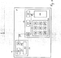
- the terminal 1 comprises a line-interface 11 coupled to said telephone line 2 and coupled via a bus 31 to a processor 12 and to terminal-memories 13 and 14 and to a printer-interface 15 and coupled via a connection 32 to telephone means 16 (microphone, speaker, etc.).
- Processor 12 is further coupled via a connection 33 to telephone means 16 and via a connection 34 to a display 17 and via a connection 35 to a keyboard-interface 18, which via a connection 36 is coupled to display 17 and via a connection 37 to a telephone-keyboard 19 and via a connection 38 to an alphanumeric-keyboard 20 and via a connection 39 to a module 21.
- Printer-interface 15 is coupled via a connection 7 to a printer 6.
- Access means 5 as disclosed in figure 3 comprise an access point 51 being provided with a network-interface 52 coupled via telephone line 4 to telephone network 3 and with a processor 53 coupled via connection 71 to network-interface 52 and via connection 72 to a data-interface 54, which is coupled to a data-connection 73.
- Access means 5 further comprise a server 61 being provided with a data-interface 62 coupled to data-connection 73 and via a bus 74 to a processor 63 and to conversion means 64 and to judging means 65 and to a server-memory 66.
- the system disclosed in figure 1 comprising the terminal 1 disclosed in figure 2 and the access means 5 disclosed in figure 3 functions as follows.
- terminal 1 will have to be provided with installation-data. This can be done according to at least three possibilities.
- the user dials a predefined telephone number via telephone-keyboard 19, which telephone number is transmitted via connection 37, keyboard-interface 18, connection 35, processor 12, bus 31, line-interface 11 and telephone line 2 to telephone network 3 as Dual Tone Multi Frequency (DTMF) signals in case of terminal 1 being an analog terminal and as digital signals in case terminal 1 being an Integrated Service Digital Network (ISDN) terminal (whereby a mixture of both kind of signals should not be excluded, like for example the possibility of post dialling in DTMF on an ISDN terminal).
- DTMF Dual Tone Multi Frequency
- telephone network 3 connects telephone line 2 to telephone line 4 under control of network-processor 42, and in access point 51 telephone line 4 is coupled via network-interface 52 and processor 53 and data-interface 54 to data-connection 73, which in server 61 is coupled via data-interface 62 and bus 74 to server-memory 66, which under control of processor 63 sends installation-data to terminal 1 (automatically or in response to a installation-command originating from terminal 1).
- This installation-data comprises for example at least one access code defining an address of an access point and at least one server code defining an address of a server address and software and/or commands.
- This installation-data is stored into terminal-memory 13 or terminal-memory 14 or spread over both terminal-memories 13 and 14.
- telephone line 2 is connected to other access means comprising at least either an other access point not shown in the figures or an other server not shown in the figures, or that telephone line 2 is only connected to network-memory 43 for the receival of said installation-data.
- At least some of said installation-data is not transmitted from server 61 to terminal 1, but is supplied to terminal 1 by the user via the use of alphanumeric-keyboard 20.
- At least some of said installation-data is neither transmitted from server 61 to terminal 1 nor supplied to terminal 1 by the user via the use of alphanumeric-keyboard 20, but is supplied to terminal 1 by the user via the insertion of a (smart) card into terminal-memory 14 being a card reader.
- the installation-data to be stored into or already stored in terminal 1 is user-dependent, for example due to the fact that a user should be able to choose his favorite access point and server, when using the first possibility different telephone numbers could be used, or in case of one telephone number different installation-commands could be used, and when using the second possibility the (smart) card should be individualised.
- Said storage of said installation-data including for example at least one access code defining an address of an access point and at least one server code defining an address of a server address and software and/or commands in a very user friendly way allows terminal 1 also to be used by users who are of a lower skilled level than for example the average user of a personal computer.
- After said storage for example only one command or even a certain key of one of said keyboards 19 and 20 could be sufficient for getting access to for example INTERNET for sending data like e-mail messages and/or taking a look at received data like e-mail messages which are stored in server-memory 66.
- a smart card further offers the possibility of storing a key signal and calculations means on said smart card.
- These calculation means calculate a response signal in response to a challenge signal and said key signal, after which said response signal is transmitted to judging means 65 inside server 61 via bus 31, line-interface 11, telephone line 2, telephone network 3, telephone line 4, access point 51, data-connection 73, data-interface 62 and bus 74.
- Judging means 65 judge whether or not said calculated response signal originating from the smart card is correct, for example by making the same calculation and comparing the results.
- the generation of said challenge signal could be realised by processor 63 comprising generation means 82, after which said challenge signal should be sent to terminal 1, or could be realised by processor 12 comprising generation means 22, after which said challenge, together with or separated from said calculated response, should be sent to server 61.
- Said smart card could further be provided with receiving means for receiving a pin code (personal identification number), whereby only in case said pin code is correct said calculation means are to be activated. Then the unauthorised use of a smart card and of a terminal comprising said smart card is made impossible.
- a smart card allows the storage of personal information on the card, whereby general information is stored into the terminal, as a consequence of which only after insertion of said smart card the terminal is individualised.
- said receiving means for receiving a pin code could also be located inside terminal 1, and/or could be used for blocking/allowing each possible terminal function and/or each possible access to said access means 5.
- Said smart card could further have more functions like payment functions and/or GSM functions, and could for example be used for encrypting/decrypting certain data to be exchanged, for example by using said key signal, in which case access means 5 should be provided with an encryption/decryption device.
- the system disclosed in figure 1 is capable of treating each user individually, which can be done in different ways.
- a user of terminal 1 can get his own screen layout on display 17, due to the fact that access means 5 have been provided with processing means for processing data destined for terminal 1 in a user-dependent way, like for example processor 63, which comprises receiving means 83 for receiving a user-dependent code from terminal 1 and comprises a configuration memory 84 for storing configuration parameters defining said screen layout.
- processing means for processing data destined for terminal 1 in a user-dependent way like for example processor 63, which comprises receiving means 83 for receiving a user-dependent code from terminal 1 and comprises a configuration memory 84 for storing configuration parameters defining said screen layout.
- either the user should generate and transmit a further code to be received by said receiving means 83, for example, or said further code is generated automatically, for example after a time-interval has expired, either in terminal 1 or in access means 5.
- the further code is generated by the user, it could be a short command, or for example a key of one of said keyboards 19 and 20.
- said special code is stored (temporarily) in server-memory 66 for example, resulting in terminal 1 automatically receiving only a predefined part of said data.
- the system disclosed in figure 1 can initiate actions, because of being provided with a self-triggering mechanism.
- This self-triggering mechanism is either in terminal 1 or in access means 5 located.
- self-triggering mechanism 85 being located in access means 5, it for example forms part of processor 63, and functions as follows.
- a comparator forming part of self-triggering mechanism 85 compares a code belonging to the new information with a code belonging to terminal 1 and for example stored in server-memory 66, and in case of equality decides that terminal 1 should be informed, or a clock forming part of self-triggering mechanism 85 decides at a certain moment, possibly after consultation of said code belonging to terminal 1 and stored in server-memory 66, that terminal 1 should be informed.
- an indication signal is generated by generation means 86 forming part of processor 63, which generation signal comprises for example an address or telephone number of terminal 1.
- This indication signal is supplied to telephone network 3 via bus 74, data-interface 62, data-connection 73, access point 51 and telephone line 4.
- Telephone network 3 then transmits this indication signal to terminal 1, in case of terminal 1 being an analog terminal via calling line identification (after a first ringing signal of a telephone call, but before a possible second ringing signal), and in case of terminal 1 being an ISDN terminal via the D-channel.
- Terminal 1 comprises receiving means 23 forming part of processor 12, which receiving means 23 receive (a part of) said indication signal via telephone line 2, line-interface 11 and bus 31, after which said indication signal is displayed via display 17, thereby informing the user of the arrival in the server of new information.
- terminal 1 could further be provided with an automatic-connection mechanism which, in response to the receival of said indication signal, automatically makes a data connection for receiving said new information, which is then stored into terminal-memory 13.
- terminal 1 When there is a connection between terminal 1 and access means 5, for example via generation means 24 which form part of processor 12, terminal 1 sends an update code to access means 5, whereby in server 61 a comparator forming part of self-triggering mechanism 85 compares this update code with codes stored in server-memory 66, and for example in case of unequality server 61 decides that terminal 1 should get an update of software, or in server 61 a clock forming part of self-triggering mechanism 85 decides at a certain moment, possibly after consultation of said update code belonging to terminal 1, that terminal 1 should get an update of software. In both cases, the update of software as for example stored in server-memory 66 is transmitted to terminal 1, for example together with an update signal informing terminal 1 what to do with said update (for example to inform which old part is to be replaced).
- the self-triggering mechanism 25 being located in terminal 1, it for example forms part of processor 12, and functions as follows.
- server 61 sends an update code to terminal 1, whereby in terminal 1 a comparator forming part of self-triggering mechanism 25 compares this update code with codes stored in terminal-memory 13, and for example in case of unequality terminal 1 decides that it should get an update of software, or in terminal 1 a clock forming part of self-triggering mechanism 25 decides at a certain moment, possibly after consultation of said update code originating from server 61, that terminal 1 should get an update of software.
- the update of software as for example stored in server-memory 66 is transmitted to terminal 1, for example together with an update signal informing terminal 1 what to do with said update (for example to inform which old part is to be replaced).
- said automatic-connection mechanism could be used for, for example under control of said self-triggering mechanism 25, automatically makes a data connection for receiving said new information etc.
- a first self-triggering mechanism (in the form of hardware and/or software) is located somewhere inside access means 5, which first self-triggering mechanism results in the transmitting of software to terminal 1, which software after being stored inside terminal 1 will function as a second self-triggering mechanism by investigating for example all software stored inside terminal 1 and deciding which software is to be replaced and then taking care of said replacement.
- the user at terminal 1 can get an overview of all messages of different types waiting for him, like telephone messages, fax messages and data messages.
- network-memory 43 and server-memory 66, which coupling is made either via telephone line 4, access point 51, data connection 73, data-interface 62 and bus 74, or via a separate connection not shown in the figures.
- network-memory 43 must send information to server 61
- server-memory 66 must send information to telephone network 3.
- the sending of said information could be done by using self-triggering mechanisms and/or automatic-connection mechanisms as described before.
- terminal-memory 13 comprises a server code defining an address of server 61 (and possibly an access code defining an address of access point 51), and comprises for example an overview code defining that an overview of all messages is required
- a user of terminal 1 may get this overview in a very userfriendly way, by for example pressing only one key or typing a short command via at least one of both keyboards 19 and 20, after which terminal 1 is connected with server 61, and server-memory 66 transmits said overview to terminal 1 for, for example, displaying this overview via display 17.
- server 61 receives new information to be stored in server-memory 66, like for example information with respect to telephone/fax messages stored in network-memory 43, or like for example data messages to be stored in server-memory 66, then either a comparator forming part of self-triggering mechanism 85 compares a first and second code belonging to the new information with a first and second code belonging to terminal 1 and for example stored in server-memory 66 (which first code for example indicates that the new information is destined for terminal 1, and which second code for example indicates that terminal 1 has already or not yet been informed with respect to the new information), and in case of respective equality and unequality decides that terminal 1 should be informed, or a clock forming part of self-triggering mechanism 85 decides at a certain moment, possibly after consultation of said codes belonging to terminal 1 and stored in server-memory 66, that terminal 1 should be informed.
- an indication signal is generated by generation means 86 forming part of processor 63, which generation signal comprises for example an address or telephone number of terminal 1 (a terminal code).
- This indication signal is supplied to telephone network 3 via bus 74, data-interface 62, data-connection 73, access point 51 and telephone line 4.
- Telephone network 3 then transmits this indication signal to terminal 1, in case of terminal 1 being an analog terminal via calling line identification (after a first ringing signal of a telephone call, but before a possible second ringing signal), and in case of terminal 1 being an ISDN terminal via the D-channel.
- Terminal 1 comprises receiving means 23 forming part of processor 12, which receiving means 23 receive (a part of) said indication signal via telephone line 2, line-interface 11 and bus 31, after which said indication signal is displayed via display 17, thereby informing the user of the arrival in the server of new information.
- terminal 1 could further be provided with an automatic-connection mechanism which, in response to the receival of said indication signal, automatically makes a data connection for receiving said new information, which is then stored into terminal-memory 13.
- the system disclosed in figure 1 is further capable of dealing with terminal 1 being connected to a printer 6 via a connection 7.
- processor 63 in server 61 is for example provided with conversion means 64 for converting data to be printed into printer data, with receiving means 88 for receiving an order code originating from terminal 1 and indicating which data is to be converted, and with generation means 89 for generating a printer code defining an address of said printer 6.
- processor 12 is for example provided with generation means 26 for generating said order code destined for server 61, and with receiving means 27 for receiving said printer code originating from server 61.
- a user using terminal 1 will decide when data has to be printed.
- terminal 1 Compared to a personal computer, which has sufficiently memory capacity and therefore is capable of converting data to be printed into printer data by using a software printer driver, terminal 1 has a predefined size and price, and therefore less memory capacity. To prevent that such a software printer driver would occupy terminal 1 too much, conversion means 64, which for example comprise such a software driver, are located in server 61.
- terminal 1 line-interface 11, bus 31 and printer-interface 15 together form switching means for switching said printer data without passing processor 12.
- said printer code to be generated by generation means 89 and for example to be sent from server 61 to terminal 1 (just) before said printer data is sent could be used to inform processor 12 of the need for a transparent mode on behalf of said printer data.
- Said order code generally could comprise the identity and/or address and/or type and/or trademark of said printer 6, to prevent that for example server 61 is overloaded with information.
- Said access point 51 can of course entirely or partially be integrated with at least telephone network 3 and/or server 61. Further, inside terminal 1, inside access point 51 and inside server 61, parts could be entirely or partially integrated.
Landscapes
- Engineering & Computer Science (AREA)
- Computer Networks & Wireless Communication (AREA)
- Signal Processing (AREA)
- Telephonic Communication Services (AREA)
- Computer And Data Communications (AREA)
- Information Transfer Between Computers (AREA)
- Exchange Systems With Centralized Control (AREA)
- Data Exchanges In Wide-Area Networks (AREA)
Priority Applications (6)
| Application Number | Priority Date | Filing Date | Title |
|---|---|---|---|
| EP97440089A EP0907275A1 (fr) | 1997-09-25 | 1997-09-25 | Terminal avec lecteur de carte |
| SG9803658-5A SG164263A1 (en) | 1997-09-25 | 1998-09-15 | Method for preparing a terminal to be used in a system, and system, and terminal |
| AU85205/98A AU750902B2 (en) | 1997-09-25 | 1998-09-16 | Method for preparing a terminal in a system for exchanging data |
| JP26592398A JP4180703B2 (ja) | 1997-09-25 | 1998-09-21 | システムにおいて使用すべき端末を準備するための方法、システム、および端末 |
| CNB981195792A CN100375471C (zh) | 1997-09-25 | 1998-09-24 | 准备用于一个系统的终端的方法以及系统和终端 |
| US09/160,749 US6067351A (en) | 1997-09-25 | 1998-09-25 | Method for preparing a terminal to be used in a system, and system, and terminal |
Applications Claiming Priority (1)
| Application Number | Priority Date | Filing Date | Title |
|---|---|---|---|
| EP97440089A EP0907275A1 (fr) | 1997-09-25 | 1997-09-25 | Terminal avec lecteur de carte |
Publications (1)
| Publication Number | Publication Date |
|---|---|
| EP0907275A1 true EP0907275A1 (fr) | 1999-04-07 |
Family
ID=8229995
Family Applications (1)
| Application Number | Title | Priority Date | Filing Date |
|---|---|---|---|
| EP97440089A Withdrawn EP0907275A1 (fr) | 1997-09-25 | 1997-09-25 | Terminal avec lecteur de carte |
Country Status (6)
| Country | Link |
|---|---|
| US (1) | US6067351A (fr) |
| EP (1) | EP0907275A1 (fr) |
| JP (1) | JP4180703B2 (fr) |
| CN (1) | CN100375471C (fr) |
| AU (1) | AU750902B2 (fr) |
| SG (1) | SG164263A1 (fr) |
Cited By (1)
| Publication number | Priority date | Publication date | Assignee | Title |
|---|---|---|---|---|
| US6906635B1 (en) | 1999-07-16 | 2005-06-14 | Alcatel | Telecommunication system including device controller with downloadable interface and remote control, and method for controlling communication system |
Families Citing this family (4)
| Publication number | Priority date | Publication date | Assignee | Title |
|---|---|---|---|---|
| US6850777B1 (en) * | 2000-03-31 | 2005-02-01 | Motorola, Inc. | Method for providing a personal identification number to a subscriber identity module |
| DE60300657T2 (de) * | 2003-08-04 | 2006-02-02 | Alcatel | Eine Methode, ein Kommunikationsnetz und ein Softwareprodukt zur Verteilung von Softwarepaketen oder Softwareupdates |
| EP1528452A1 (fr) * | 2003-10-27 | 2005-05-04 | Alcatel | Détection, protection et suppression recursives de virus des noeuds d'un réseau de données |
| US9723033B2 (en) * | 2015-06-08 | 2017-08-01 | Asustek Computer Inc. | Router |
Citations (6)
| Publication number | Priority date | Publication date | Assignee | Title |
|---|---|---|---|---|
| JPH04178058A (ja) * | 1990-11-13 | 1992-06-25 | Meidensha Corp | 電子メールシステムの端末装置 |
| JPH0897852A (ja) * | 1994-09-22 | 1996-04-12 | N T T Data Tsushin Kk | モバイルメ−ルシステム |
| FR2737797A1 (fr) * | 1995-07-25 | 1997-02-14 | Germaneau Benoit Luc Gildas | Carte de visite electronique |
| WO1997008906A1 (fr) * | 1995-08-30 | 1997-03-06 | Sendit Ab | Systeme et dispositif hote pour transmettre du courrier electronique |
| WO1997015008A1 (fr) * | 1995-06-06 | 1997-04-24 | At & T Ipm Corp. | Systeme et procede de controle de l'acces aux bases de donnees |
| US5649131A (en) * | 1992-12-30 | 1997-07-15 | Lucent Technologies Inc. | Communications protocol |
Family Cites Families (2)
| Publication number | Priority date | Publication date | Assignee | Title |
|---|---|---|---|---|
| SE470001B (sv) * | 1991-09-12 | 1993-10-18 | Televerket | Förfarande för identifiering och kryptonyckelutbyte mellan två kommunicerande apparater för krypterad trafik |
| US5757891A (en) * | 1995-06-26 | 1998-05-26 | Wang; Kevin Kuan-Pin | Ever ready telephonic answering-machine for receiving and delivering electronic messages |
-
1997
- 1997-09-25 EP EP97440089A patent/EP0907275A1/fr not_active Withdrawn
-
1998
- 1998-09-15 SG SG9803658-5A patent/SG164263A1/en unknown
- 1998-09-16 AU AU85205/98A patent/AU750902B2/en not_active Ceased
- 1998-09-21 JP JP26592398A patent/JP4180703B2/ja not_active Expired - Fee Related
- 1998-09-24 CN CNB981195792A patent/CN100375471C/zh not_active Expired - Fee Related
- 1998-09-25 US US09/160,749 patent/US6067351A/en not_active Expired - Lifetime
Patent Citations (6)
| Publication number | Priority date | Publication date | Assignee | Title |
|---|---|---|---|---|
| JPH04178058A (ja) * | 1990-11-13 | 1992-06-25 | Meidensha Corp | 電子メールシステムの端末装置 |
| US5649131A (en) * | 1992-12-30 | 1997-07-15 | Lucent Technologies Inc. | Communications protocol |
| JPH0897852A (ja) * | 1994-09-22 | 1996-04-12 | N T T Data Tsushin Kk | モバイルメ−ルシステム |
| WO1997015008A1 (fr) * | 1995-06-06 | 1997-04-24 | At & T Ipm Corp. | Systeme et procede de controle de l'acces aux bases de donnees |
| FR2737797A1 (fr) * | 1995-07-25 | 1997-02-14 | Germaneau Benoit Luc Gildas | Carte de visite electronique |
| WO1997008906A1 (fr) * | 1995-08-30 | 1997-03-06 | Sendit Ab | Systeme et dispositif hote pour transmettre du courrier electronique |
Non-Patent Citations (4)
| Title |
|---|
| "ELECTRONIC MAIL MIT PAGER", FUNKSCHAU, vol. 68, no. 4, 2 February 1996 (1996-02-02), pages 72/73, XP000553426 * |
| ECKARDT T ET AL: "ON THE PERSONAL COMMUNICATIONS IMPACTS ON MULTIMEDIA TELESERVICES", MULTIMEDIA: ADVANCED TELESERVICES AND HIGH-SPEED COMMUNICATIONARCHITECTURES. INTERNATIONAL WORKSHOP, XX, XX, 26 September 1994 (1994-09-26), pages 435 - 449, XP000613104 * |
| PATENT ABSTRACTS OF JAPAN vol. 016, no. 486 (E - 1276) 8 October 1992 (1992-10-08) * |
| PATENT ABSTRACTS OF JAPAN vol. 096, no. 008 30 August 1996 (1996-08-30) * |
Cited By (1)
| Publication number | Priority date | Publication date | Assignee | Title |
|---|---|---|---|---|
| US6906635B1 (en) | 1999-07-16 | 2005-06-14 | Alcatel | Telecommunication system including device controller with downloadable interface and remote control, and method for controlling communication system |
Also Published As
| Publication number | Publication date |
|---|---|
| CN100375471C (zh) | 2008-03-12 |
| JPH11175444A (ja) | 1999-07-02 |
| JP4180703B2 (ja) | 2008-11-12 |
| CN1221281A (zh) | 1999-06-30 |
| US6067351A (en) | 2000-05-23 |
| SG164263A1 (en) | 2010-09-29 |
| AU750902B2 (en) | 2002-08-01 |
| AU8520598A (en) | 1999-04-15 |
Similar Documents
| Publication | Publication Date | Title |
|---|---|---|
| US6594032B1 (en) | Facsimile apparatus and electronic mail server | |
| US6049596A (en) | Individualized system for exchanging data between a terminal and access means via a telephone network, and terminal, and access means | |
| US6825955B1 (en) | Method and apparatus for facsimile that notifies an e-mail transmission using facsimile protocol | |
| US5825990A (en) | Error reporting method for facsimile system | |
| EP0907274B1 (fr) | Système avec dispositif d'impression pour l'échange de données entre un terminal et des moyens d'accès | |
| US6463293B1 (en) | Method for preparing a terminal to be used in a system, and system and terminal | |
| US6067351A (en) | Method for preparing a terminal to be used in a system, and system, and terminal | |
| US6075846A (en) | Unified system for exchanging data between a terminal and access means via a telephone network, and access means, and terminal | |
| US6233321B1 (en) | Push/pull system for exchanging data between a terminal and access means via a telephone network, and terminal, and access means | |
| US6934374B2 (en) | System and method for data communication | |
| JP3882494B2 (ja) | 通信端末装置 | |
| HK1020641A (en) | Unified system for exchanging data between a terminal and access means via a telephone network, and access means, and terminal | |
| HK1019980A (en) | Method for preparing a terminal to be used in a system, and system, and terminal | |
| EP0773664A2 (fr) | Procédé et appareil pour la fourniture d'informations d'état dans des transmissions de télécopie | |
| HK1019975A (en) | Individualised system for exchanging data between a terminal and access means via a telephone network, and terminal, and access means | |
| HK1019974A (en) | Push/pull system for exchanging data between a terminal and access means via a telephone network, and terminal, and access means | |
| EP2187614B1 (fr) | Dispositif de communication de données d'image et procédé de communication pour ceci | |
| HK1020640A (en) | Printer-option system for exchanging data between a terminal and access means via a telephone network, and access means, and terminal | |
| JP2002077503A (ja) | ファクシミリシステム及びゲートウェイ装置 | |
| JP2002290618A (ja) | 転送機能付き通信端末装置 | |
| JPH08107460A (ja) | 情報の蓄積又は提供方法及びその装置 |
Legal Events
| Date | Code | Title | Description |
|---|---|---|---|
| PUAI | Public reference made under article 153(3) epc to a published international application that has entered the european phase |
Free format text: ORIGINAL CODE: 0009012 |
|
| 17P | Request for examination filed |
Effective date: 19980904 |
|
| AK | Designated contracting states |
Kind code of ref document: A1 Designated state(s): DE ES FR GB IT SE |
|
| AKX | Designation fees paid |
Free format text: DE ES FR GB IT SE |
|
| 17Q | First examination report despatched |
Effective date: 20020828 |
|
| RAP1 | Party data changed (applicant data changed or rights of an application transferred) |
Owner name: ALCATEL LUCENT |
|
| RAP1 | Party data changed (applicant data changed or rights of an application transferred) |
Owner name: ALCATEL LUCENT |
|
| GRAP | Despatch of communication of intention to grant a patent |
Free format text: ORIGINAL CODE: EPIDOSNIGR1 |
|
| RIC1 | Information provided on ipc code assigned before grant |
Ipc: H04L 12/58 20060101AFI20130321BHEP Ipc: G06F 3/00 20060101ALN20130321BHEP |
|
| INTG | Intention to grant announced |
Effective date: 20130411 |
|
| 111Z | Information provided on other rights and legal means of execution |
Free format text: DE ES FR GB IT SE Effective date: 20130410 |
|
| STAA | Information on the status of an ep patent application or granted ep patent |
Free format text: STATUS: THE APPLICATION IS DEEMED TO BE WITHDRAWN |
|
| 18D | Application deemed to be withdrawn |
Effective date: 20130822 |