EP0907310A2 - Dispositif de connexion pour conducteur de puissance soumis à des contraintes thermiques pour redresseurs et autres - Google Patents
Dispositif de connexion pour conducteur de puissance soumis à des contraintes thermiques pour redresseurs et autres Download PDFInfo
- Publication number
- EP0907310A2 EP0907310A2 EP98117786A EP98117786A EP0907310A2 EP 0907310 A2 EP0907310 A2 EP 0907310A2 EP 98117786 A EP98117786 A EP 98117786A EP 98117786 A EP98117786 A EP 98117786A EP 0907310 A2 EP0907310 A2 EP 0907310A2
- Authority
- EP
- European Patent Office
- Prior art keywords
- heat
- connection device
- heat sink
- contact
- current conductors
- Prior art date
- Legal status (The legal status is an assumption and is not a legal conclusion. Google has not performed a legal analysis and makes no representation as to the accuracy of the status listed.)
- Granted
Links
- 239000004020 conductor Substances 0.000 claims abstract description 26
- 238000001816 cooling Methods 0.000 claims abstract description 4
- 230000001681 protective effect Effects 0.000 claims description 2
- 238000010276 construction Methods 0.000 abstract description 4
- 239000002470 thermal conductor Substances 0.000 description 6
- 229910001369 Brass Inorganic materials 0.000 description 2
- 230000000712 assembly Effects 0.000 description 2
- 238000000429 assembly Methods 0.000 description 2
- 239000010951 brass Substances 0.000 description 2
- 230000017525 heat dissipation Effects 0.000 description 2
- 239000000463 material Substances 0.000 description 2
- 238000005516 engineering process Methods 0.000 description 1
- 239000011152 fibreglass Substances 0.000 description 1
- 239000011810 insulating material Substances 0.000 description 1
- 238000004519 manufacturing process Methods 0.000 description 1
- 229920005573 silicon-containing polymer Polymers 0.000 description 1
- 229920001169 thermoplastic Polymers 0.000 description 1
- 239000004416 thermosoftening plastic Substances 0.000 description 1
- 238000009423 ventilation Methods 0.000 description 1
Images



Classifications
-
- H—ELECTRICITY
- H02—GENERATION; CONVERSION OR DISTRIBUTION OF ELECTRIC POWER
- H02G—INSTALLATION OF ELECTRIC CABLES OR LINES, OR OF COMBINED OPTICAL AND ELECTRIC CABLES OR LINES
- H02G5/00—Installations of bus-bars
- H02G5/10—Cooling
-
- H—ELECTRICITY
- H05—ELECTRIC TECHNIQUES NOT OTHERWISE PROVIDED FOR
- H05K—PRINTED CIRCUITS; CASINGS OR CONSTRUCTIONAL DETAILS OF ELECTRIC APPARATUS; MANUFACTURE OF ASSEMBLAGES OF ELECTRICAL COMPONENTS
- H05K7/00—Constructional details common to different types of electric apparatus
- H05K7/20—Modifications to facilitate cooling, ventilating, or heating
- H05K7/2089—Modifications to facilitate cooling, ventilating, or heating for power electronics, e.g. for inverters for controlling motor
- H05K7/209—Heat transfer by conduction from internal heat source to heat radiating structure
-
- H—ELECTRICITY
- H01—ELECTRIC ELEMENTS
- H01R—ELECTRICALLY-CONDUCTIVE CONNECTIONS; STRUCTURAL ASSOCIATIONS OF A PLURALITY OF MUTUALLY-INSULATED ELECTRICAL CONNECTING ELEMENTS; COUPLING DEVICES; CURRENT COLLECTORS
- H01R4/00—Electrically-conductive connections between two or more conductive members in direct contact, i.e. touching one another; Means for effecting or maintaining such contact; Electrically-conductive connections having two or more spaced connecting locations for conductors and using contact members penetrating insulation
- H01R4/28—Clamped connections, spring connections
- H01R4/30—Clamped connections, spring connections utilising a screw or nut clamping member
- H01R4/34—Conductive members located under head of screw
Definitions
- connection device for Conductors under thermal load, especially in converters or the like, according to claim 1; such connection devices are part of electronic assemblies Devices such as inverters, DC / DC converters, Chargers or the like and are used for contacting of thermally loaded busbars, via which e.g. outer feed lines connected to components of the device are.
- connection device allows for simpler Manufacturing and assembly technology via the heat sink a quick and direct dissipation of the unwanted operating heat from the electrical conductors to the heat sink; thereby can the construction volume of such a device and its Weight and its costs due to the possible waiver additional fans and / or more thermally specified Reduce components significantly.
- According to one embodiment of the invention is still more extensive Simplification provided as a heat sink between the current conductor on the one hand and the heat sink on the other a screw, in particular a standard screw, in the clipboard to hold the heat sink with its screw head heat-contacted and at the free threaded shaft end of the Current conductor can be screwed on directly for making contact.
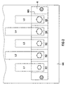
- connection device with one on the Surface of a heat sink KK arranged clipboard K with five contact connections K1-K5 for five current conductors L1-L5 in Shape of flat busbars; the clipboard K with the contact connections K1-K5 for the current conductors L1-L5 is inside a cup-shaped protective hood SH arranged with the heat sink KK thus a closed device interior forms, in which the connection device with the thermally loaded Current conductors L1-L5 is included.
- the contact connections K1-K5 are essentially each from a contact socket KB1-KB2, which like the clipboard K preferably made of an electrically insulating thermoplastic is formed, and one of these contact socket KB1-KB5 each recorded, in particular injected, e.g. made of brass existing heat sink W1-W5.
- the The free contact end facing away from the heat sink KK are the heat conducting bodies W1-W5 using screws S1-S5 with as a current conductor L1-L5 provided flat busbars contacted and at their opposite ends in indirect or immediate Thermal connection with the surface of the heat sink KK asked.
- FIG. 3 shows a first embodiment of a contact connection, in which a heat conducting body W2 made of brass in a contact socket KB2 of the terminal board K is injected; into a threaded bush A screw S2 can be screwed into the heat-conducting body W2 and thereby by a current of great amperage thermal conductor L2 with a KS cable lug a line leading to the outside, e.g. to control a Electric motor, electric and in particular thermally conductive Can be contacted with the thermal conductor W2.
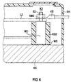
- FIG. 4 shows a further comparison with the embodiment according to FIG. 3 simplified, but in terms of heat dissipation to the Heat sink KK equally effective configuration according to the invention; for this purpose, the heat-conducting body W2 itself is on its conductor-side One-piece end as screw S2 with a threaded shaft trained, onto which a screw nut SM2 can be screwed is and in turn the conductor L2 with the Cable lug KS2 electrical and especially with the thermal conductor W2 combines intensive heat-conducting.
- FIG. 5 shown in FIG. 5 is the thermal conductor W2 with a one-piece threaded shaft 4 replaced by one injected into the contact socket KB2 Standard screw S2, such that on the one hand their SK2 screw head with simple positive overmolding protection in the clipboard K a large-area heat conduction to the Heatsink KK can guarantee and on the other hand on their Free threaded shaft end protruding from the KB2 contact socket a screw nut SM2 for contacting the current conductor L2 with the KS cable lug and the W2 thermal conductor can be screwed on in the form of the standard screw S2.
- this intermediate thermal layer WS is for additional Improvement of heat dissipation between the heat conducting bodies W1-W5 and the surface of the heat sink KK an intermediate thermal layer WS provided such that the heat of the individual, if necessary, different heat-loaded thermal conductors W1-W5 as large and even as possible the surface of the heat sink KK is distributable.
- this intermediate thermal layer WS consists of electrical insulating material; such materials are on known and consist for example of elastic, with Aluminumoxys filled "low modulus silicone polymer" on one Fiberglass backing. Due to the material flexibility of this Thermally conductive intermediate layer can be advantageously also surface irregularities, especially of the heat sink, balance in terms of good heat distribution.
Landscapes
- Engineering & Computer Science (AREA)
- Microelectronics & Electronic Packaging (AREA)
- Physics & Mathematics (AREA)
- Thermal Sciences (AREA)
- Cooling Or The Like Of Electrical Apparatus (AREA)
- Connections Effected By Soldering, Adhesion, Or Permanent Deformation (AREA)
- Cable Accessories (AREA)
Applications Claiming Priority (2)
| Application Number | Priority Date | Filing Date | Title |
|---|---|---|---|
| DE29717550U DE29717550U1 (de) | 1997-10-01 | 1997-10-01 | Anschlußvorrichtung für thermisch belastete Stromleiter, insbesondere in Umrichtern o.dgl. |
| DE29717550U | 1997-10-01 |
Publications (3)
| Publication Number | Publication Date |
|---|---|
| EP0907310A2 true EP0907310A2 (fr) | 1999-04-07 |
| EP0907310A3 EP0907310A3 (fr) | 1999-11-03 |
| EP0907310B1 EP0907310B1 (fr) | 2004-08-18 |
Family
ID=8046727
Family Applications (1)
| Application Number | Title | Priority Date | Filing Date |
|---|---|---|---|
| EP98117786A Expired - Lifetime EP0907310B1 (fr) | 1997-10-01 | 1998-09-18 | Dispositif de connexion pour conducteur de puissance soumis à des contraintes thermiques pour redresseurs et autres |
Country Status (2)
| Country | Link |
|---|---|
| EP (1) | EP0907310B1 (fr) |
| DE (2) | DE29717550U1 (fr) |
Cited By (8)
| Publication number | Priority date | Publication date | Assignee | Title |
|---|---|---|---|---|
| WO2000074138A1 (fr) * | 1999-05-31 | 2000-12-07 | Siemens Aktiengesellschaft | Dispositif pour refroidir un composant electrique |
| WO2000074457A1 (fr) * | 1999-05-31 | 2000-12-07 | Siemens Aktiengesellschaft | Commutateur |
| WO2004047225A3 (fr) * | 2002-01-16 | 2004-08-12 | Rockwell Automation Tech Inc | Convertisseur de puissance compact refroidi par fluide supportant des cartes de circuit multiples |
| DE102016011087A1 (de) | 2015-09-17 | 2017-03-23 | Sew-Eurodrive Gmbh & Co Kg | Anordnung zum Anschließen der Leitungen eines elektrischen Kabels und Elektrogerät mit einer solchen Anordnung |
| WO2018054638A1 (fr) * | 2016-09-22 | 2018-03-29 | Robert Bosch Gmbh | Ensemble électronique, en particulier ensemble électronique de puissance pour véhicules hybrides ou véhicules électriques |
| DE102018218163A1 (de) | 2018-10-24 | 2020-04-30 | Zf Friedrichshafen Ag | Schnittstellenmodul, Wechselrichter und Fahrzeug |
| US11111137B2 (en) | 2016-08-29 | 2021-09-07 | Robert Bosch Gmbh | Method for manufacturing a micromechanical sensor |
| EP4626148A1 (fr) * | 2024-03-18 | 2025-10-01 | MB Elettronica S.R.L. | Elément pour l'extraction de courants électriques de haute intensité d'une carte électronique montée sur un dissipateur thermique métallique et réalisé par la technologie des substrats métalliques |
Families Citing this family (4)
| Publication number | Priority date | Publication date | Assignee | Title |
|---|---|---|---|---|
| DE10129788B4 (de) * | 2001-06-20 | 2005-11-10 | Siemens Ag | Kunststoffrahmen zur Montage eines elektronischen Starkstrom-Steuergeräts |
| US7032695B2 (en) | 2002-01-16 | 2006-04-25 | Rockwell Automation Technologies, Inc. | Vehicle drive module having improved terminal design |
| US7187568B2 (en) | 2002-01-16 | 2007-03-06 | Rockwell Automation Technologies, Inc. | Power converter having improved terminal structure |
| DE102016113424A1 (de) * | 2016-07-20 | 2018-01-25 | Getrag Getriebe- Und Zahnradfabrik Hermann Hagenmeyer Gmbh & Cie Kg | Klemmenblock für eine elektrische Verbindung |
Family Cites Families (11)
| Publication number | Priority date | Publication date | Assignee | Title |
|---|---|---|---|---|
| US4060847A (en) * | 1976-03-11 | 1977-11-29 | Power Management Corporation | Cooling arrangement for electrical power contactor |
| DE3041656A1 (de) * | 1980-11-05 | 1982-05-13 | SEMIKRON Gesellschaft für Gleichrichterbau u. Elektronik mbH, 8500 Nürnberg | Halbleiter-schaltungsaufbau |
| EP0064856B1 (fr) * | 1981-05-12 | 1986-12-30 | LUCAS INDUSTRIES public limited company | Un arrangement à pont multi-phase |
| EP0249646B1 (fr) * | 1986-06-18 | 1990-02-28 | C.A. Weidmüller GmbH & Co. | Borne de raccordement à une plaquette de circuit imprimé |
| DE8709364U1 (de) * | 1987-07-07 | 1988-11-03 | Siemens AG, 1000 Berlin und 8000 München | Elektrisches Aggregat |
| DE8801086U1 (de) * | 1988-01-29 | 1988-03-10 | Siemens AG, 1000 Berlin und 8000 München | Verspanneinrichtung zum Kontaktieren elektrischer Hochstromleiter |
| DE8911408U1 (de) * | 1989-09-25 | 1991-01-31 | Siemens Ag, 8000 Muenchen | Kastenförmiges Gehäuse mit einer eingebauten mehrphasigen elektronischen Halbleiterschaltungsanordnung |
| FR2657223A1 (fr) * | 1990-01-12 | 1991-07-19 | Portenseigne Radiotechnique | Systeme de montage d'un transistor avec refroidisseur. |
| DE9015107U1 (de) * | 1990-11-02 | 1991-02-28 | Klöckner-Moeller GmbH, 5300 Bonn | Vorrichtung zur Kühlung von Stromschienen |
| US5579217A (en) * | 1991-07-10 | 1996-11-26 | Kenetech Windpower, Inc. | Laminated bus assembly and coupling apparatus for a high power electrical switching converter |
| JP2725952B2 (ja) * | 1992-06-30 | 1998-03-11 | 三菱電機株式会社 | 半導体パワーモジュール |
-
1997
- 1997-10-01 DE DE29717550U patent/DE29717550U1/de not_active Expired - Lifetime
-
1998
- 1998-09-18 DE DE59811828T patent/DE59811828D1/de not_active Expired - Fee Related
- 1998-09-18 EP EP98117786A patent/EP0907310B1/fr not_active Expired - Lifetime
Cited By (12)
| Publication number | Priority date | Publication date | Assignee | Title |
|---|---|---|---|---|
| WO2000074138A1 (fr) * | 1999-05-31 | 2000-12-07 | Siemens Aktiengesellschaft | Dispositif pour refroidir un composant electrique |
| WO2000074457A1 (fr) * | 1999-05-31 | 2000-12-07 | Siemens Aktiengesellschaft | Commutateur |
| WO2004047225A3 (fr) * | 2002-01-16 | 2004-08-12 | Rockwell Automation Tech Inc | Convertisseur de puissance compact refroidi par fluide supportant des cartes de circuit multiples |
| DE102016011087A1 (de) | 2015-09-17 | 2017-03-23 | Sew-Eurodrive Gmbh & Co Kg | Anordnung zum Anschließen der Leitungen eines elektrischen Kabels und Elektrogerät mit einer solchen Anordnung |
| US11111137B2 (en) | 2016-08-29 | 2021-09-07 | Robert Bosch Gmbh | Method for manufacturing a micromechanical sensor |
| WO2018054638A1 (fr) * | 2016-09-22 | 2018-03-29 | Robert Bosch Gmbh | Ensemble électronique, en particulier ensemble électronique de puissance pour véhicules hybrides ou véhicules électriques |
| CN109716877A (zh) * | 2016-09-22 | 2019-05-03 | 罗伯特·博世有限公司 | 电子组件、尤其是用于混合动力车或者电动车的电子的功率组件 |
| US20200022279A1 (en) * | 2016-09-22 | 2020-01-16 | Robert Bosch Gmbh | Electronic module, in particular an electronic power module for hybrid vehicles or electric vehicles |
| US11051432B2 (en) | 2016-09-22 | 2021-06-29 | Robert Bosch Gmbh | Electronic module, in particular an electronic power module for hybrid vehicles or electric vehicles |
| CN109716877B (zh) * | 2016-09-22 | 2021-09-07 | 罗伯特·博世有限公司 | 电子组件 |
| DE102018218163A1 (de) | 2018-10-24 | 2020-04-30 | Zf Friedrichshafen Ag | Schnittstellenmodul, Wechselrichter und Fahrzeug |
| EP4626148A1 (fr) * | 2024-03-18 | 2025-10-01 | MB Elettronica S.R.L. | Elément pour l'extraction de courants électriques de haute intensité d'une carte électronique montée sur un dissipateur thermique métallique et réalisé par la technologie des substrats métalliques |
Also Published As
| Publication number | Publication date |
|---|---|
| DE29717550U1 (de) | 1998-10-29 |
| DE59811828D1 (de) | 2004-09-23 |
| EP0907310B1 (fr) | 2004-08-18 |
| EP0907310A3 (fr) | 1999-11-03 |
Similar Documents
| Publication | Publication Date | Title |
|---|---|---|
| EP0907310B1 (fr) | Dispositif de connexion pour conducteur de puissance soumis à des contraintes thermiques pour redresseurs et autres | |
| DE102016119631B4 (de) | Leistungshalbleitermodul mit einem Druckeinleitkörper und Anordnung hiermit | |
| DE10258570B4 (de) | Leistungshalbleitermodul | |
| EP3358921B1 (fr) | Dispositif électronique de puissance et véhicule correspondant | |
| DE102008062514A1 (de) | Halbleitermodul-Montagekonstruktion | |
| DE102022103218A1 (de) | Invertervorrichtung mit einer laminierten Sammelschiene oder einer Hochstrom-leiterplatte | |
| EP2716145B1 (fr) | Carte de circuits imprimés pour composants électriques et systèmes de cartes de circuits imprimés | |
| EP0264364B1 (fr) | Appareil de commutation electrique | |
| EP3223592B1 (fr) | Unité de commande électronique destinée au fonctionnement d'un moteur électrique comprenant une résistance de freinage | |
| DE202010017443U1 (de) | Elektrische Baugruppe | |
| DE102016206234A1 (de) | Stromschiene für einen Wechselrichter, Wechselrichter und Kraftfahrzeugantriebsystem | |
| EP0076292A1 (fr) | Contact electrique, notamment pour circuits imprimes de petits appareils electriques. | |
| DE102018219880B4 (de) | Leistungselektrikanordnung | |
| DE102015107188A1 (de) | Leistungselektronikeinrichtung | |
| DE3308350C2 (de) | Befestigungsvorrichtung zur elektrisch isolierenden und wärmeleitenden Befestigung elektrischer Bauelemente an Kühlkörper | |
| DE102015213916A1 (de) | Leistungshalbleitermodulanordnung | |
| DE102020216305B4 (de) | Elektrische Schaltvorrichtung | |
| BE1032601B1 (de) | Antriebseinheit für ein Lenksystem eines Kraftfahrzeugs | |
| EP4486080A1 (fr) | Ensemble électronique de puissance à structure améliorée | |
| DE102022208468B3 (de) | Steckeradapter und elektronische Anordnung | |
| DE69919259T2 (de) | Substrat für eine Baugruppe von elektronischen Bauteilen einer elektrischen Maschine | |
| DE102019107080B4 (de) | Anordnung mit einer Leiterplatte und einem zu entwärmenden Leistungshalbleiterbauelement | |
| DE102024100922A1 (de) | Stromschienenbefestigung zum Befestigen einer Hochvolt-Stromschiene und Hochvoltsystem mit einer entsprechenden Stromschienenbefestigung | |
| DE102022133512A1 (de) | Leistungshalbleitermodul mit einem Gehäuse, einer leistungselektronischen Baugruppe und mit einem Formkörper | |
| DE3316577A1 (de) | Befestigungsvorrichtung zur elektrisch isolierenden und waermeleitenden befestigung elektrischer bauelemente an kuehlkoerper |
Legal Events
| Date | Code | Title | Description |
|---|---|---|---|
| PUAI | Public reference made under article 153(3) epc to a published international application that has entered the european phase |
Free format text: ORIGINAL CODE: 0009012 |
|
| AK | Designated contracting states |
Kind code of ref document: A2 Designated state(s): DE FR IT |
|
| AX | Request for extension of the european patent |
Free format text: AL;LT;LV;MK;RO;SI |
|
| PUAL | Search report despatched |
Free format text: ORIGINAL CODE: 0009013 |
|
| AK | Designated contracting states |
Kind code of ref document: A3 Designated state(s): AT BE CH CY DE DK ES FI FR GB GR IE IT LI LU MC NL PT SE |
|
| AX | Request for extension of the european patent |
Free format text: AL;LT;LV;MK;RO;SI |
|
| RIC1 | Information provided on ipc code assigned before grant |
Free format text: 6H 05K 7/20 A, 6H 01R 4/34 B, 6H 02M 7/00 B, 6H 01L 23/50 B |
|
| 17P | Request for examination filed |
Effective date: 19991206 |
|
| AKX | Designation fees paid |
Free format text: DE FR IT |
|
| GRAP | Despatch of communication of intention to grant a patent |
Free format text: ORIGINAL CODE: EPIDOSNIGR1 |
|
| RTI1 | Title (correction) |
Free format text: CONNECTING DEVICE FOR POWER LEADS SUBJECTED TO THERMAL STRESSES, PARTICULARLY FOR RECTIFIERS OR SIMILAR |
|
| GRAA | (expected) grant |
Free format text: ORIGINAL CODE: 0009210 |
|
| GRAS | Grant fee paid |
Free format text: ORIGINAL CODE: EPIDOSNIGR3 |
|
| AK | Designated contracting states |
Kind code of ref document: B1 Designated state(s): DE FR IT |
|
| REF | Corresponds to: |
Ref document number: 59811828 Country of ref document: DE Date of ref document: 20040923 Kind code of ref document: P |
|
| ET | Fr: translation filed | ||
| PLBE | No opposition filed within time limit |
Free format text: ORIGINAL CODE: 0009261 |
|
| STAA | Information on the status of an ep patent application or granted ep patent |
Free format text: STATUS: NO OPPOSITION FILED WITHIN TIME LIMIT |
|
| 26N | No opposition filed |
Effective date: 20050519 |
|
| PGFP | Annual fee paid to national office [announced via postgrant information from national office to epo] |
Ref country code: IT Payment date: 20080924 Year of fee payment: 11 Ref country code: FR Payment date: 20080912 Year of fee payment: 11 |
|
| PGFP | Annual fee paid to national office [announced via postgrant information from national office to epo] |
Ref country code: DE Payment date: 20080919 Year of fee payment: 11 |
|
| REG | Reference to a national code |
Ref country code: FR Ref legal event code: ST Effective date: 20100531 |
|
| PG25 | Lapsed in a contracting state [announced via postgrant information from national office to epo] |
Ref country code: FR Free format text: LAPSE BECAUSE OF NON-PAYMENT OF DUE FEES Effective date: 20090930 Ref country code: DE Free format text: LAPSE BECAUSE OF NON-PAYMENT OF DUE FEES Effective date: 20100401 |
|
| PG25 | Lapsed in a contracting state [announced via postgrant information from national office to epo] |
Ref country code: IT Free format text: LAPSE BECAUSE OF NON-PAYMENT OF DUE FEES Effective date: 20090918 |