EP0907442B1 - Verfahren zur optimierung der strangoberflächenqualität - Google Patents
Verfahren zur optimierung der strangoberflächenqualität Download PDFInfo
- Publication number
- EP0907442B1 EP0907442B1 EP97922831A EP97922831A EP0907442B1 EP 0907442 B1 EP0907442 B1 EP 0907442B1 EP 97922831 A EP97922831 A EP 97922831A EP 97922831 A EP97922831 A EP 97922831A EP 0907442 B1 EP0907442 B1 EP 0907442B1
- Authority
- EP
- European Patent Office
- Prior art keywords
- strand
- casting
- mould
- friction
- time behaviour
- Prior art date
- Legal status (The legal status is an assumption and is not a legal conclusion. Google has not performed a legal analysis and makes no representation as to the accuracy of the status listed.)
- Expired - Lifetime
Links
Images


Classifications
-
- B—PERFORMING OPERATIONS; TRANSPORTING
- B22—CASTING; POWDER METALLURGY
- B22D—CASTING OF METALS; CASTING OF OTHER SUBSTANCES BY THE SAME PROCESSES OR DEVICES
- B22D11/00—Continuous casting of metals, i.e. casting in indefinite lengths
- B22D11/16—Controlling or regulating processes or operations
- B22D11/165—Controlling or regulating processes or operations for the supply of casting powder
-
- B—PERFORMING OPERATIONS; TRANSPORTING
- B22—CASTING; POWDER METALLURGY
- B22D—CASTING OF METALS; CASTING OF OTHER SUBSTANCES BY THE SAME PROCESSES OR DEVICES
- B22D11/00—Continuous casting of metals, i.e. casting in indefinite lengths
- B22D11/16—Controlling or regulating processes or operations
- B22D11/166—Controlling or regulating processes or operations for mould oscillation
Definitions
- the present invention relates to a method on a casting plant for production of strands, especially steel strands.
- the strand When casting steel strands in continuous casting plants, the strand is generally conveyed at a constant take-off speed.
- the level of the casting mirror in the The mold is kept constant by regulating the feed of the melt from the distributor.
- a suitable hydraulic mold drive system is from DE 35 43 790 C2 known.
- the formation of the strand surface in addition to the type of lubrication between Chill mold and strand shell also changes within the mold, e.g. B. caused by oscillation parameters (stroke height, stroke frequency, curve shape) as well as the steel grade itself, the strand withdrawal speed, the cooling conditions as well as the steel temperature and also the type of strand guide, especially when Casting rollers are important, can only be seen by comparing the Mold oscillation curves in empty operation compared to the casting operation none draw immediate conclusions that would be suitable in the casting business immediately intervene.
- oscillation parameters stroke height, stroke frequency, curve shape
- the strand speed in the mold is considered assumed uniform speed, probably due to the fact that the strand withdrawal is accomplished by means of uniformly rotating rollers becomes.
- the actual strand speed is determined by the Friction in the mold significantly affected. This is at one point, at times The up and down movement of the strand can be seen with the naked eye (see Steel u. Eisen (1987), No. 14, 15, pages 673 to 677. It is from DE 38 06 583 A1 known, the movement of the strand in an area as immediately as possible to detect after leaving the mold, the measurement signals by a Diode line camera fed to an evaluation unit or a display unit become.
- the method known from this document serves for natural vibrations of the line or the system and the driving style of the whole Adjust the system so that critical areas are avoided.
- a method according to the preamble of claim 1 is from DE-A-3806583 known.
- the determined distance-time signal is fed to a computer and the Setpoint value of the line speed is formed from the path-time behavior of the line.
- DE-A-2743579 from which it is known, is also mentioned Change mold powder composition, depending on certain Casting parameters, such as mold acceleration.
- the invention aims to find an improvement of the known measuring methods, the an immediate influence on controllable operating parameters to improve the Surface quality allowed.
- the measuring method delivers as Original information the temporal course of the strand path.
- the path averaged over time is the relative path or the relative speed at the nominal distance or at the nominal speed. From the deviation from the actual and A control signal for changing the mold powder composition in the sense of a setpoint is Reduction of the coefficient of friction and / or the mold oscillation formed.
- the friction work or the friction power in the drive system mold lifting table, and influencing variables are determined according to the given target values optimized.
- the signal for changing the Mold oscillation of a control unit of the oscillation drive in the way switched on that the motion impulse transmitted from the mold to the strand is as small as possible or is close to zero. It is proposed as a measured value in the hydraulic drive between the differential pressure in the hydraulic cylinder Idle and operating state to use the measured value. A mechanical one This value can be obtained by a load cell.
- the strand lubrication has a great influence on the coefficient of friction.
- the casting powder should be in be changed in such a way that the coefficient of friction is reduced.
- the mixing ratio of different casting powders to each other change and possibly influence the physical state of the mold powder in the way take that it at least softens through preheating and may is liquefied before it is fed to the melt in the mold.
- the mold 12 is connected to a mold powder feed, which Barriers 16 is connected to the powder container 15.
- the Powder feed 17 is also guided through a heating device 18.
- a sensor is provided on the narrow side of the strand 11, here one Diode line camera, which detects the diode lines of the string, the camera in their alignment with the casting direction.
- the diode line camera 21 is connected to the measurement receptacle 22 for a measurement line 28 the strand movement with respect to distance 24 and speed 23 is connected.
- the signals relating to the change in line speed and line path a computer 26 and possibly a display device 25, possibly a printer, fed.
- the computer 26 is connected to a control line 31 Control component 32 with actuators 16 regular gate valve Casting powder container 15 and via a control component 33 with the heating device 18 connected for the mold powder.
- the computer 26 is also connected to a control component 35 via a control line 34 linked to control the oscillation 13.
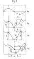
- Fig. 2 shows a typical expression of detected measurement signals.
- the upper part is a Section of the mean speed of the mold shown in the given Example oscillates according to a sine curve.
- the curve shown is a Example and shows characteristic actual forms with evaluable points. From the Arrangement of the minima, maxima and the turning points is the expert Possibility to draw conclusions about the actual behavior of the strand shell to pull the mold. For assessment, he uses the position of the strand to the - Time T with the curve shapes at points A. The distance S is the direct derivative of the speed V.
Landscapes
- Engineering & Computer Science (AREA)
- Mechanical Engineering (AREA)
- Continuous Casting (AREA)
- Casting Devices For Molds (AREA)
- General Factory Administration (AREA)
- Processing And Handling Of Plastics And Other Materials For Molding In General (AREA)
- Formation And Processing Of Food Products (AREA)
- Mold Materials And Core Materials (AREA)
Description
- Fig 1
- die prinzipielle Aufschaltung,
- Fig. 2
- einen typischen Ausdruck und
- Fig. 3
- die Variationen der Wegkurven des Stranges.
Claims (6)
- Verfahren an einer Gießanlage zur Erzeugung von Strängen, insbesondere von Stahlsträngen, bei dem flüssiges Metall in eine Durchlaufkokille eingeführt und im teilerstarrten Zustand aus der Kokille abgezogen wird, der Bewegungsablauf des Stranges in einem Bereich möglichst unmittelbar nach Verlassen der Kokille erfaßt wird, das Erfassen des Bewegungsablaufs berührungslos und verzögerungsfrei durch auf Strahlung ansprechende Sensoren erfolgt und die Sensoren derart ausgelegt und angeordnet sind, daß sie ein auswertbares Meßsignal über das Weg-Zeit-Verhalten des Stranges erzeugen, gekennzeichnet durch folgende Verfahrensschritte,a) die Gießspiegeloberfläche wird mit einem eine flüssige Schlacke bildenden Gießpulver zur Erzeugung eines Schmierfilmes zwischen Strangschale und innerer Kokillenwand abgedeckt,b) ein die Reibung zwischen Strangschale und Kokillenwand charakterisierender Meßwert wird in der Oszillationseinrichtung erfaßt und der als Rechner ausgebildeten Auswerteinheit zugeführt,c) das das Weg-Zeit-Verhalten des Stranges charakterisierende Meßsignal wird ebenfalls dem Rechner zugeführt,d) im Rechner werden die Meßwerte bzw. Signale aus dem Weg-Zeit-Verhalten des Stranges und der Reibung des Stranges in der Kokille zu vergleichbaren Größen korreliert und verknüpft und mit einem Sollwert verglichen, wobeie) der Sollwert als Mittelwert der Stranggeschwindigkeit aus dem Weg-Zeit-Verhalten des Stranges gebildet ist,f) aus der Abweichung von Ist- und Sollwert wird ein Signal zur Änderung der Gießpulverzusammensetzung im Sinne einer Herabsetzung des Reibungsbeiwertes und/oder der Kokillenoszillation gebildet,g) wobei das Weg-Zeit-Verhalten des Stranges optisch durch eine seitlich neben dem Strang an seiner Schmalseite angeordnete Diodenzeilenkamera, die in ihrer Ausrichtung mit der Gießrichtung übereinstimmt, erfaßt wird.
- Verfahren nach Anspruch 1,
dadurch gekennzeichnet,
daß das Signal zur Änderung der Kokillenoszillation einer Steuereinheit des Oszillationsantriebes derart aufgeschaltet wird, daß der von der Kokille auf den Strang übertragene Bewegungsimpuls möglichst gering ist oder nahe am Wert Null liegt. - Verfahren nach Anspruch 1,
dadurch gekennzeichnet,
daß der die Reibung des Stranges in der Kokille charakterisierende Meßwert bei hydraulischem Antrieb der Kokillenoszillationseinrichtung aus dem Differenzdruck im Hydraulikzylinder zwischen Leerlauf und Betriebszustand gebildet ist. - Verfahren nach Anspruch 1,
dadurch gekennzeichnet,
daß der die Reibung des Stranges in der Kokille charakterisierende Meßwert bei mechanischem Antrieb einer im Oszillationsgestänge angeordneten Kraftmeßzelle entnommen ist. - Verfahren nach Anspruch 1,
dadurch gekennzeichnet,
daß das Mischungsverhältnis verschiedener Gießpulver zueinander verändert wird. - Verfahren nach den Ansprüchen 5 oder 1,
dadurch gekennzeichnet,
daß der Aggregatzustand des Gießpulvers vor seinem Kontakt mit dem flüssigen Metall in der Kokille verändert wird, z.B. Erweichen oder Verflüssigen durch Zufuhr von Wärmeenergie.
Applications Claiming Priority (3)
| Application Number | Priority Date | Filing Date | Title |
|---|---|---|---|
| DE19614760 | 1996-04-02 | ||
| DE19614760A DE19614760A1 (de) | 1996-04-02 | 1996-04-02 | Verfahren zur Optimierung der Strangoberflächenqualität |
| PCT/DE1997/000732 WO1997036706A1 (de) | 1996-04-02 | 1997-04-02 | Verfahren zur optimierung der strangoberflächenqualität |
Publications (2)
| Publication Number | Publication Date |
|---|---|
| EP0907442A1 EP0907442A1 (de) | 1999-04-14 |
| EP0907442B1 true EP0907442B1 (de) | 2001-05-30 |
Family
ID=7791274
Family Applications (1)
| Application Number | Title | Priority Date | Filing Date |
|---|---|---|---|
| EP97922831A Expired - Lifetime EP0907442B1 (de) | 1996-04-02 | 1997-04-02 | Verfahren zur optimierung der strangoberflächenqualität |
Country Status (12)
| Country | Link |
|---|---|
| EP (1) | EP0907442B1 (de) |
| JP (1) | JP3130053B2 (de) |
| CN (1) | CN1072067C (de) |
| AT (1) | ATE201623T1 (de) |
| AU (1) | AU722408B2 (de) |
| BR (1) | BR9708495A (de) |
| CA (1) | CA2250871A1 (de) |
| DE (2) | DE19614760A1 (de) |
| ES (1) | ES2157072T3 (de) |
| RU (1) | RU2163856C2 (de) |
| UA (1) | UA44840C2 (de) |
| WO (1) | WO1997036706A1 (de) |
Families Citing this family (5)
| Publication number | Priority date | Publication date | Assignee | Title |
|---|---|---|---|---|
| ITRM980258A1 (it) * | 1998-04-23 | 1999-10-23 | Acciai Speciali Terni Spa | Procedimento per la produzione in colata continua di bramme esenti da difettosita' superficiali e bramme cosi' ottenute |
| KR101790001B1 (ko) * | 2016-03-02 | 2017-11-20 | 주식회사 포스코 | 용융물 주입 장치, 이를 이용한 주조설비 및 주조방법 |
| WO2018105652A1 (ja) * | 2016-12-06 | 2018-06-14 | 新日鐵住金株式会社 | 溶融金属表面のスラグ体積評価方法 |
| JP6984728B2 (ja) * | 2018-03-02 | 2021-12-22 | 日本製鉄株式会社 | 鋳片の製造方法及び連続鋳造設備 |
| CN115121771B (zh) * | 2022-07-27 | 2023-06-09 | 西北工业大学 | 一种金属型材智能化超声连铸方法及测控装置 |
Family Cites Families (7)
| Publication number | Priority date | Publication date | Assignee | Title |
|---|---|---|---|---|
| CH559075A5 (de) * | 1973-05-30 | 1975-02-28 | Concast Ag | |
| DE2743579A1 (de) * | 1976-10-05 | 1978-04-06 | Centre Rech Metallurgique | Verfahren zur steuerung des stranggiessens von metallen |
| AT367328B (de) * | 1980-04-29 | 1982-06-25 | Vnii Avtom Chernoi Metallurg | Vorrichtung zur automatischen zugkraftmessung beim stranggiessen |
| DE3367341D1 (en) * | 1982-02-24 | 1986-12-11 | Kawasaki Steel Co | Method of controlling continuous casting facility |
| JPH0235622B2 (ja) * | 1984-08-24 | 1990-08-13 | Nippon Kokan Kk | Renzokuchuzoniokerubureekuautoyochihoho |
| DE3806583A1 (de) * | 1988-02-26 | 1989-09-07 | Mannesmann Ag | Verfahren an einer giessanlage zur erzeugung von straengen |
| DE19515316C1 (de) * | 1995-04-19 | 1996-08-29 | Mannesmann Ag | Verfahren zum Betreiben einer Kokille |
-
1996
- 1996-04-02 DE DE19614760A patent/DE19614760A1/de not_active Withdrawn
-
1997
- 1997-04-02 UA UA98105197A patent/UA44840C2/uk unknown
- 1997-04-02 JP JP09534837A patent/JP3130053B2/ja not_active Expired - Fee Related
- 1997-04-02 CN CN97193564A patent/CN1072067C/zh not_active Expired - Fee Related
- 1997-04-02 ES ES97922831T patent/ES2157072T3/es not_active Expired - Lifetime
- 1997-04-02 DE DE59703679T patent/DE59703679D1/de not_active Expired - Lifetime
- 1997-04-02 AU AU28857/97A patent/AU722408B2/en not_active Ceased
- 1997-04-02 WO PCT/DE1997/000732 patent/WO1997036706A1/de not_active Ceased
- 1997-04-02 RU RU98119841/02A patent/RU2163856C2/ru not_active IP Right Cessation
- 1997-04-02 BR BR9708495A patent/BR9708495A/pt not_active IP Right Cessation
- 1997-04-02 EP EP97922831A patent/EP0907442B1/de not_active Expired - Lifetime
- 1997-04-02 CA CA002250871A patent/CA2250871A1/en not_active Abandoned
- 1997-04-02 AT AT97922831T patent/ATE201623T1/de active
Also Published As
| Publication number | Publication date |
|---|---|
| CN1072067C (zh) | 2001-10-03 |
| DE19614760A1 (de) | 1997-10-09 |
| BR9708495A (pt) | 1999-08-03 |
| JP3130053B2 (ja) | 2001-01-31 |
| AU2885797A (en) | 1997-10-22 |
| ES2157072T3 (es) | 2001-08-01 |
| UA44840C2 (uk) | 2002-03-15 |
| CN1215357A (zh) | 1999-04-28 |
| JPH11513936A (ja) | 1999-11-30 |
| CA2250871A1 (en) | 1997-10-09 |
| DE59703679D1 (de) | 2001-07-05 |
| AU722408B2 (en) | 2000-08-03 |
| EP0907442A1 (de) | 1999-04-14 |
| WO1997036706A1 (de) | 1997-10-09 |
| ATE201623T1 (de) | 2001-06-15 |
| RU2163856C2 (ru) | 2001-03-10 |
Similar Documents
| Publication | Publication Date | Title |
|---|---|---|
| EP0980295B1 (de) | Verfahren und vorrichtung zum erzeugen von brammen aus stahl | |
| DE69425507T2 (de) | Verfahren und vorrichtung zum walzengiessen dunner bleche | |
| DE3423475C2 (de) | Verfahren und Einrichtung zum Stranggießen von flüssigen Metallen, insbesondere von flüssigem Stahl | |
| DE69615534T2 (de) | Stranggiessverfahren und -anlage | |
| EP0907442B1 (de) | Verfahren zur optimierung der strangoberflächenqualität | |
| DE4117073C2 (de) | ||
| EP0325931B1 (de) | Verfahren und Vorrichtung zum Oszillieren einer Stahlstranggiesskokille | |
| DE2414514A1 (de) | Stranggiessverfahren | |
| EP0114293B1 (de) | Verfahren und Vorrichtung zur Einstellung der Konizität von Schmalseitenwänden von Stranggiesskokillen | |
| EP1536900B1 (de) | Verfahren und vorrichtung zum starten eines giessvorganges | |
| EP3554744B1 (de) | Verfahren und vorrichtung zum regeln einer stranggiessanlage | |
| DE4444123C2 (de) | Druckgießverfahren und Druckgießvorrichtung | |
| EP3733323B1 (de) | Verfahren und stranggiessanlage zum giessen eines giessstrangs | |
| EP3628416B1 (de) | Verfahren und anlage zum stranggiessen eines metallischen produkts | |
| AT519154B1 (de) | Regelung der Schmalseitenkonizität einer Stranggusskokille | |
| EP1149648A1 (de) | Verfahren und Vorrichtung zur thermischen Kontrolle einer Stranggiesskokille | |
| EP0331612B1 (de) | Verfahren an einer Giessanlage zur Erzeugung von Strängen | |
| EP0120338B1 (de) | Verfahren zur Ermittlung der Kokillenwandabnutzung während des Giessprozesses und zur Ermittlung der Abhebung der Strangschale von der Kokilleninnenwand | |
| DE3126385C2 (de) | Verfahren zum Stranggießen von Stahlbrammen | |
| DE4433932A1 (de) | Druck- oder Spritzgießmaschine | |
| EP1385656B1 (de) | Verfahren zum stranggiessen von blöcken, brammen oder dünnbrammen | |
| DE2901407A1 (de) | Verfahren und vorrichtung zum steuern und regeln beim metallstrangguss | |
| DE69303309T2 (de) | Verfahren zum Stranggiessen | |
| DE3939728A1 (de) | Druck- und spritzgiessmaschine | |
| EP1365873B1 (de) | Verfahren zum ermitteln von kenndaten eines oszillationssystems einer oszillierenden stranggiesskokille |
Legal Events
| Date | Code | Title | Description |
|---|---|---|---|
| PUAI | Public reference made under article 153(3) epc to a published international application that has entered the european phase |
Free format text: ORIGINAL CODE: 0009012 |
|
| 17P | Request for examination filed |
Effective date: 19980909 |
|
| AK | Designated contracting states |
Kind code of ref document: A1 Designated state(s): AT BE DE ES FI FR GB IT NL |
|
| 17Q | First examination report despatched |
Effective date: 19990607 |
|
| RAP1 | Party data changed (applicant data changed or rights of an application transferred) |
Owner name: SMS DEMAG AG |
|
| GRAG | Despatch of communication of intention to grant |
Free format text: ORIGINAL CODE: EPIDOS AGRA |
|
| GRAG | Despatch of communication of intention to grant |
Free format text: ORIGINAL CODE: EPIDOS AGRA |
|
| GRAH | Despatch of communication of intention to grant a patent |
Free format text: ORIGINAL CODE: EPIDOS IGRA |
|
| GRAH | Despatch of communication of intention to grant a patent |
Free format text: ORIGINAL CODE: EPIDOS IGRA |
|
| GRAA | (expected) grant |
Free format text: ORIGINAL CODE: 0009210 |
|
| AK | Designated contracting states |
Kind code of ref document: B1 Designated state(s): AT BE DE ES FI FR GB IT NL |
|
| REF | Corresponds to: |
Ref document number: 201623 Country of ref document: AT Date of ref document: 20010615 Kind code of ref document: T |
|
| GBT | Gb: translation of ep patent filed (gb section 77(6)(a)/1977) |
Effective date: 20010530 |
|
| REF | Corresponds to: |
Ref document number: 59703679 Country of ref document: DE Date of ref document: 20010705 |
|
| REG | Reference to a national code |
Ref country code: ES Ref legal event code: FG2A Ref document number: 2157072 Country of ref document: ES Kind code of ref document: T3 |
|
| ITF | It: translation for a ep patent filed | ||
| ET | Fr: translation filed | ||
| REG | Reference to a national code |
Ref country code: GB Ref legal event code: IF02 |
|
| PGFP | Annual fee paid to national office [announced via postgrant information from national office to epo] |
Ref country code: NL Payment date: 20020328 Year of fee payment: 6 |
|
| PGFP | Annual fee paid to national office [announced via postgrant information from national office to epo] |
Ref country code: FI Payment date: 20020402 Year of fee payment: 6 |
|
| PLBE | No opposition filed within time limit |
Free format text: ORIGINAL CODE: 0009261 |
|
| PGFP | Annual fee paid to national office [announced via postgrant information from national office to epo] |
Ref country code: BE Payment date: 20020415 Year of fee payment: 6 |
|
| PGFP | Annual fee paid to national office [announced via postgrant information from national office to epo] |
Ref country code: FR Payment date: 20020416 Year of fee payment: 6 |
|
| PGFP | Annual fee paid to national office [announced via postgrant information from national office to epo] |
Ref country code: ES Payment date: 20020418 Year of fee payment: 6 |
|
| 26N | No opposition filed | ||
| PG25 | Lapsed in a contracting state [announced via postgrant information from national office to epo] |
Ref country code: FI Free format text: LAPSE BECAUSE OF NON-PAYMENT OF DUE FEES Effective date: 20030402 |
|
| PG25 | Lapsed in a contracting state [announced via postgrant information from national office to epo] |
Ref country code: ES Free format text: LAPSE BECAUSE OF NON-PAYMENT OF DUE FEES Effective date: 20030403 |
|
| PG25 | Lapsed in a contracting state [announced via postgrant information from national office to epo] |
Ref country code: BE Free format text: LAPSE BECAUSE OF NON-PAYMENT OF DUE FEES Effective date: 20030430 |
|
| BERE | Be: lapsed |
Owner name: *SMS DEMAG A.G. Effective date: 20030430 |
|
| PG25 | Lapsed in a contracting state [announced via postgrant information from national office to epo] |
Ref country code: NL Free format text: LAPSE BECAUSE OF NON-PAYMENT OF DUE FEES Effective date: 20031101 |
|
| NLV4 | Nl: lapsed or anulled due to non-payment of the annual fee |
Effective date: 20031101 |
|
| REG | Reference to a national code |
Ref country code: ES Ref legal event code: FD2A Effective date: 20030403 |
|
| PG25 | Lapsed in a contracting state [announced via postgrant information from national office to epo] |
Ref country code: FR Free format text: LAPSE BECAUSE OF NON-PAYMENT OF DUE FEES Effective date: 20030430 |
|
| PGFP | Annual fee paid to national office [announced via postgrant information from national office to epo] |
Ref country code: DE Payment date: 20110421 Year of fee payment: 15 |
|
| PGFP | Annual fee paid to national office [announced via postgrant information from national office to epo] |
Ref country code: AT Payment date: 20110414 Year of fee payment: 15 Ref country code: GB Payment date: 20110421 Year of fee payment: 15 |
|
| PGFP | Annual fee paid to national office [announced via postgrant information from national office to epo] |
Ref country code: IT Payment date: 20110422 Year of fee payment: 15 |
|
| REG | Reference to a national code |
Ref country code: AT Ref legal event code: MM01 Ref document number: 201623 Country of ref document: AT Kind code of ref document: T Effective date: 20120402 |
|
| GBPC | Gb: european patent ceased through non-payment of renewal fee |
Effective date: 20120402 |
|
| PG25 | Lapsed in a contracting state [announced via postgrant information from national office to epo] |
Ref country code: GB Free format text: LAPSE BECAUSE OF NON-PAYMENT OF DUE FEES Effective date: 20120402 Ref country code: AT Free format text: LAPSE BECAUSE OF NON-PAYMENT OF DUE FEES Effective date: 20120402 |
|
| PG25 | Lapsed in a contracting state [announced via postgrant information from national office to epo] |
Ref country code: IT Free format text: LAPSE BECAUSE OF NON-PAYMENT OF DUE FEES Effective date: 20120402 |
|
| REG | Reference to a national code |
Ref country code: DE Ref legal event code: R119 Ref document number: 59703679 Country of ref document: DE Effective date: 20121101 |
|
| PG25 | Lapsed in a contracting state [announced via postgrant information from national office to epo] |
Ref country code: DE Free format text: LAPSE BECAUSE OF NON-PAYMENT OF DUE FEES Effective date: 20121101 |