EP0907853B1 - Federnde unterstützung - Google Patents
Federnde unterstützung Download PDFInfo
- Publication number
- EP0907853B1 EP0907853B1 EP97908361A EP97908361A EP0907853B1 EP 0907853 B1 EP0907853 B1 EP 0907853B1 EP 97908361 A EP97908361 A EP 97908361A EP 97908361 A EP97908361 A EP 97908361A EP 0907853 B1 EP0907853 B1 EP 0907853B1
- Authority
- EP
- European Patent Office
- Prior art keywords
- arm
- end parts
- support according
- directions
- support
- Prior art date
- Legal status (The legal status is an assumption and is not a legal conclusion. Google has not performed a legal analysis and makes no representation as to the accuracy of the status listed.)
- Expired - Lifetime
Links
Images

Classifications
-
- F—MECHANICAL ENGINEERING; LIGHTING; HEATING; WEAPONS; BLASTING
- F01—MACHINES OR ENGINES IN GENERAL; ENGINE PLANTS IN GENERAL; STEAM ENGINES
- F01N—GAS-FLOW SILENCERS OR EXHAUST APPARATUS FOR MACHINES OR ENGINES IN GENERAL; GAS-FLOW SILENCERS OR EXHAUST APPARATUS FOR INTERNAL-COMBUSTION ENGINES
- F01N13/00—Exhaust or silencing apparatus characterised by constructional features
- F01N13/18—Construction facilitating manufacture, assembly, or disassembly
- F01N13/1805—Fixing exhaust manifolds, exhaust pipes or pipe sections to each other, to engine or to vehicle body
- F01N13/1811—Fixing exhaust manifolds, exhaust pipes or pipe sections to each other, to engine or to vehicle body with means permitting relative movement, e.g. compensation of thermal expansion or vibration
- F01N13/1822—Fixing exhaust manifolds, exhaust pipes or pipe sections to each other, to engine or to vehicle body with means permitting relative movement, e.g. compensation of thermal expansion or vibration for fixing exhaust pipes or devices to vehicle body
-
- B—PERFORMING OPERATIONS; TRANSPORTING
- B60—VEHICLES IN GENERAL
- B60K—ARRANGEMENT OR MOUNTING OF PROPULSION UNITS OR OF TRANSMISSIONS IN VEHICLES; ARRANGEMENT OR MOUNTING OF PLURAL DIVERSE PRIME-MOVERS IN VEHICLES; AUXILIARY DRIVES FOR VEHICLES; INSTRUMENTATION OR DASHBOARDS FOR VEHICLES; ARRANGEMENTS IN CONNECTION WITH COOLING, AIR INTAKE, GAS EXHAUST OR FUEL SUPPLY OF PROPULSION UNITS IN VEHICLES
- B60K13/00—Arrangement in connection with combustion air intake or gas exhaust of propulsion units
- B60K13/04—Arrangement in connection with combustion air intake or gas exhaust of propulsion units concerning exhaust
-
- F—MECHANICAL ENGINEERING; LIGHTING; HEATING; WEAPONS; BLASTING
- F16—ENGINEERING ELEMENTS AND UNITS; GENERAL MEASURES FOR PRODUCING AND MAINTAINING EFFECTIVE FUNCTIONING OF MACHINES OR INSTALLATIONS; THERMAL INSULATION IN GENERAL
- F16L—PIPES; JOINTS OR FITTINGS FOR PIPES; SUPPORTS FOR PIPES, CABLES OR PROTECTIVE TUBING; MEANS FOR THERMAL INSULATION IN GENERAL
- F16L3/00—Supports for pipes, cables or protective tubing, e.g. hangers, holders, clamps, cleats, clips, brackets
- F16L3/16—Supports for pipes, cables or protective tubing, e.g. hangers, holders, clamps, cleats, clips, brackets with special provision allowing movement of the pipe
-
- F—MECHANICAL ENGINEERING; LIGHTING; HEATING; WEAPONS; BLASTING
- F16—ENGINEERING ELEMENTS AND UNITS; GENERAL MEASURES FOR PRODUCING AND MAINTAINING EFFECTIVE FUNCTIONING OF MACHINES OR INSTALLATIONS; THERMAL INSULATION IN GENERAL
- F16L—PIPES; JOINTS OR FITTINGS FOR PIPES; SUPPORTS FOR PIPES, CABLES OR PROTECTIVE TUBING; MEANS FOR THERMAL INSULATION IN GENERAL
- F16L55/00—Devices or appurtenances for use in, or in connection with, pipes or pipe systems
- F16L55/02—Energy absorbers; Noise absorbers
- F16L55/033—Noise absorbers
- F16L55/035—Noise absorbers in the form of specially adapted hangers or supports
Definitions
- the invention relates to a resilient support for resiliently supporting a vibratable member from a relatively rigid structure, comprising a first end part having a front face and a rear face and being adapted for connection to the structure, and a second end part having a front face and a rear face and being adapted for connection to the vibratable member, and arm means resiliently connecting the first and second end parts together such that vibration of the member relative to the structure tends to move the first and second end parts away from and towards each other, the arm means comprising at least a first arm made of resilient material connected to the first and second end parts for resiliently resisting the vibrations.
- Such a support is known, for example from EP-A-0 411 246.
- the known support is usable for supporting part of the exhaust system of a motor vehicle.
- Such a support resists the vibrations of the exhaust system relative to the supporting structure of the vehicle. It is desirable, though, to arrange for such a support to have resistance also to forces acting in a sideways direction.
- the invention aims to deal with this problem.
- the known support is characterised in that the first and second end parts face in opposite directions and the first arm is resiliently connected to the end parts and extends between corresponding faces of the end parts in a direction diagonal to the vibration directions whereby vibrations are resisted by tension and compression in the arm and by bending where the arm is resiliently connected to the end parts and whereby movement of the vibratable member relative to the structure in directions transverse to the vibration directions is resisted in one of those transverse directions substantially by tension in the arm and in the other of the transverse directions by a combination of compression in the arm and bending therein.
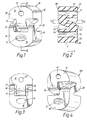
- the resilient support 10 of Figure 1 is for resiliently supporting or suspending part of the exhaust system, such as an exhaust pipe, of a motor vehicle, from the body or chassis of the vehicle.
- the support 10 is made of elastomeric material such as rubber or other strong resilient material and is preferably made by a moulding process.
- the rubber is moulded to provide two through holes 12 and 14 for receiving stiff metal attachment hooks.
- a first metal hook passes through the bore 12 and is attached, above the support 10, to a fixed point on the body or chassis of the vehicle.
- a second stiff metal hook passes through the bore 14 and extends below the support 10 into attachment to the exhaust pipe.
- the bore 12 in this example is circular in cross-section, while the bore 14 is oval. Of course, other shapes may be used instead.
- the support 10 comprises upper and lower end blocks 16 and 18 which are integrally connected together by three arms, that is, an inner arm 22 and two outer arms 24 and 26.
- the upper and lower blocks 16,18 are of generally the same external shape except that they face in opposite directions.
- the inner arm 22 extends from the front face 28 of the upper block 16 to the corresponding face 30 of the lower block 18.
- the two outer arms 24,26 extend from the rear face 32 of the upper block 16 to the corresponding face 34 of the lower block 18.
- the support 10 operates mainly in traction in the vertical direction, because of the force exerted by the mass of the suspended structure (the exhaust pipe).
- the arms 22,24,26 are subjected to both tension and deflectional forces, the latter arising where the ends of the arms are "hinged" to the upper and lower blocks 16,18.
- the flexibility of the arms thus permits a certain degree of vertical up and down movement, and the rubber material thus helps to isolate vibration of the exhaust system from the vehicle body and also provides good damping characteristics.
- the exhaust system may also be subjected to forces tending to move it sideways, such forces of course being transmitted to the support 10 and thus tending to move the lower block 18 along the y axis shown in Figure 2 relative to the upper block 16. It is important that the support 10 provides significant resistance to such movement in order to prevent the exhaust system coming into contact with an adjacent rigid part of the vehicle body and thus causing unpleasant "knocking", as well as possible damage. If such movement takes place in the Y + direction, that is, in the direction of the y axis shown in Figure 2, the inner arm 22 will be subjected mainly to tension forces, whereas the outer arms 24 and 26 will be subjected to a combination of compression and bending.
- the outer arms 24,26 are subjected mainly to tension while the inner arm 22 is subjected to a combination of compression and bending.
- the arms 22,24 and 26 provide high resistance to the sideways movement and thus help to resist knocking.
- the support thus has a relatively low value of K z /K y , where K z is the rigidity in the vertical direction and K y is the rigidity in the transverse or y direction (Y + or Y ).
- K z /K y close to 1 can be achieved, in contrast to more usual values of the order of 2.
- the value of K z /K y is affected by the values for the angles alpha 1 and alpha 2 shown in Figure 2.
- the angle alpha 1 is the angle between the horizontal and the median direction of the central arm 22.
- the angle alpha 2 is the angle between the horizontal and the median direction of the outer arm 24 (or the other outer arm 26).
- the smaller the value of alpha 1 and alpha 2 the lower will be the value of the ratio K z /K y .
- the damping characteristics of the support are affected by the following factors (among others):-
- elastomeric connections 36 may be integrally moulded between the inner arm 22 and the outer arms 24,26.
- Figure 4 shows a modified form 10A of the support of Figure 1.
- the support 10A differs from the support 10 in that the support 10A does not have an inner arm 22 but only two outer arms 24 and 26, and these are directed in opposite directions.
- the operation of the support 10A is generally similar to that of the support 10. It is normally advantageous to have an odd number of arms (as in the support 10) because this gives the support a plane of symmetry YZ.
- the two outer arms 24,26 of the support 10A can be interconnected by an integrally moulded connection 36A as shown dotted in Figure 5.
Landscapes
- Engineering & Computer Science (AREA)
- General Engineering & Computer Science (AREA)
- Mechanical Engineering (AREA)
- Chemical & Material Sciences (AREA)
- Combustion & Propulsion (AREA)
- Transportation (AREA)
- Vibration Prevention Devices (AREA)
- Exhaust Silencers (AREA)
Claims (10)
- Elastische Lagerung, um elastisch ein vibrierendes Bauteil gegenüber einer relativ steifen Struktur zu lagern, mit einem ersten Endstück (16), das eine Vorderfläche (28) und eine Rückfläche (32) aufweist und daran angepaßt ist, mit der Struktur verbunden zu werden, sowie mit einem zweiten Endstück (18), das eine Vorderfläche (30) und eine Rückfläche (34) aufweist und daran angepaßt ist, mit dem vibrierenden Bauteil verbunden zu werden, und mit Armteilen (22, 24, 26), die das erste und zweite Endstück (16, 18) elastisch miteinander verbinden, so daß eine Vibration des Bauteils relativ zur Struktur dazu neigt, das erste und zweite Endstück (16, 18) voneinander fort und aufeinander zu zu bewegen, wobei die Armteile wenigstens einen ersten aus einem elastischen Material hergestellten Arm umfassen, der mit dem ersten und zweiten Endstück (16, 18) verbunden ist, um elastisch der Vibration zu widerstehen,
dadurch gekennzeichnet,
daß die ersten und zweiten Endstücke (16, 18) in unterschiedliche Richtungen weisen und der erste Arm (22, 24, 26) elastisch mit den Endstücken (16, 18) verbunden ist und sich zwischen entsprechenden Flächen (28, 30; 32, 34) der Endstücke (16, 18) in eine Richtung diagonal zu den Richtungen der Vibration erstreckt, wodurch den Vibrationen durch Dehnung und Stauchung in dem Arm (22, 24, 26) und durch Biegen an der Stelle, wo der Arm elastisch mit den Endstücken (16, 18) verbunden ist, widerstanden wird und wodurch der Bewegung des vibrierenden Bauteils relativ zur Struktur in Richtungen quer zu den Richtungen der Vibration in einer dieser Querrichtungen durch Dehnung in dem Arm und in der anderen der Querrichtungen durch eine Kombination aus Stauchung und Biegung in dem Arm widerstanden wird. - Lagerung nach Anspruch 1, dadurch gekennzeichnet, daß das Armteil einen zweiten Arm (22, 24, 26) ähnlich dem ersten Arm (22, 24, 26) einschließt.
- Lagerung nach Anspruch 2, dadurch gekennzeichnet, daß sich die zwei Arme (22; 24 oder 26) in diagonal entgegengesetzte Richtungen erstrecken.
- Lagerung nach Anspruch 2, dadurch gekennzeichnet, daß sich die zwei Arme (24, 26) diagonal in dieselbe Richtung erstrecken und dadurch, daß das Armteil einen dritten Arm (22) einschließt, der zwischen den ersten und zweiten Armen (24, 26) angeordnet ist und sich in eine diagonal entgegengesetzte Richtung zu diesen erstreckt.
- Lagerung nach einem der Ansprüche 2 bis 4, gekennzeichnet durch eine elastische Verbindung (36) zwischen angrenzenden Armen (22, 24, 26) an der Stelle, wo diese sich diagonal überkreuzen.
- Lagerung nach einem der vorhergehenden Ansprüche, dadurch gekennzeichnet, daß die ersten und zweiten Endstücke (16, 18) und die Armteile (22, 24, 26) einstückig aus einem elastomeren Material hergestellt sind.
- Lagerung nach Anspruch 6, dadurch gekennzeichnet, daß diese gegossen ist.
- Lagerung nach Anspruch 7, dadurch gekennzeichnet, daß diese aus einem elastomeren Material wie beispielsweise Gummi gegossen ist.
- Lagerung nach einem der vorhergehenden Ansprüche, dadurch gekennzeichnet, daß das vibrierende Bauteil ein Teil des Abgassystems eines Kraftfahrzeuges ist und die relativ starre Struktur der Rumpf oder die Karosserie dieses Kraftfahrzeuges ist.
- Lagerung nach einem der vorhergehenden Ansprüche, gekennzeichnet durch Begrenzungsmittel (40), um das Maß zu begrenzen, um das sich die zwei Endstücke (16, 18) als Antwort auf die Vibrationsbewegung voneinander fort bewegen können.
Applications Claiming Priority (3)
| Application Number | Priority Date | Filing Date | Title |
|---|---|---|---|
| GB9613830 | 1996-07-02 | ||
| GB9613830A GB2314907B (en) | 1996-07-02 | 1996-07-02 | Resilient supports |
| PCT/GB1997/000740 WO1998000661A1 (en) | 1996-07-02 | 1997-03-18 | Resilient supports |
Publications (2)
| Publication Number | Publication Date |
|---|---|
| EP0907853A1 EP0907853A1 (de) | 1999-04-14 |
| EP0907853B1 true EP0907853B1 (de) | 1999-12-22 |
Family
ID=10796190
Family Applications (1)
| Application Number | Title | Priority Date | Filing Date |
|---|---|---|---|
| EP97908361A Expired - Lifetime EP0907853B1 (de) | 1996-07-02 | 1997-03-18 | Federnde unterstützung |
Country Status (6)
| Country | Link |
|---|---|
| US (1) | US6170782B1 (de) |
| EP (1) | EP0907853B1 (de) |
| DE (1) | DE69701000T2 (de) |
| ES (1) | ES2140219T3 (de) |
| GB (1) | GB2314907B (de) |
| WO (1) | WO1998000661A1 (de) |
Families Citing this family (9)
| Publication number | Priority date | Publication date | Assignee | Title |
|---|---|---|---|---|
| DE19825811C1 (de) * | 1998-06-09 | 1999-11-18 | Sgf Gmbh & Co Kg | Aufhängeöse für eine schwingende Last, insbes. für eine Abgasanlage eines Kraftfahrzeugs |
| DE10257660B3 (de) * | 2002-12-10 | 2004-08-26 | Trelleborg Automotive Technical Centre Gmbh | Haltevorrichtung, insbesondere zum elastischen Aufhängen einer Abgasanlage eines Kraftfahrzeugs |
| DE10301370B4 (de) * | 2003-01-16 | 2005-03-03 | Woco Avs Gmbh | Frequenz- und dehnungsoptimierte Halteschlaufe |
| FR2867246B1 (fr) * | 2004-03-02 | 2006-06-02 | Hutchinson | Dispositif de liaison antivibratoire |
| US7644911B2 (en) * | 2005-09-22 | 2010-01-12 | The Pullman Company | Isolator |
| US20070131469A1 (en) * | 2005-12-08 | 2007-06-14 | Hyo-Seok Kim | Power train mounting apparatus of vehicle |
| US8146898B2 (en) * | 2009-11-12 | 2012-04-03 | Miner Elastomer Products Corporation | Elastomeric compression spring |
| CN104118315A (zh) * | 2013-04-25 | 2014-10-29 | 重庆长安汽车股份有限公司 | 一种吊耳 |
| CN107379960A (zh) * | 2017-08-08 | 2017-11-24 | 威固技术(安徽)有限公司 | 一种汽车排气系统用低动静比吊耳橡胶件 |
Family Cites Families (23)
| Publication number | Priority date | Publication date | Assignee | Title |
|---|---|---|---|---|
| GB508702A (en) * | 1938-01-07 | 1939-07-05 | Vauxhall Motors Ltd | Flexible mounting for reciprocating engines, pumps, compressors and the like |
| GB718605A (en) * | 1951-10-03 | 1954-11-17 | Nat Res Dev | Improvements in and relating to resilient mountings for machinery and the like |
| US3161252A (en) * | 1962-01-22 | 1964-12-15 | Gen Motors Corp | Exhaust system hanger for motor vehicles |
| US3204901A (en) * | 1963-11-13 | 1965-09-07 | Ford Motor Co | Motor vehicle exhaust pipe support |
| US3270992A (en) * | 1965-10-05 | 1966-09-06 | Gen Motors Corp | Exhaust system hanger |
| US3289984A (en) * | 1966-03-11 | 1966-12-06 | Viking Auto Products Inc | Automotive exhaust pipe support |
| US4019599A (en) * | 1973-09-27 | 1977-04-26 | Tenneco Inc. | Spring type pipe support |
| DE2353619A1 (de) * | 1973-10-26 | 1975-05-15 | Continental Gummi Werke Ag | Elastisches lager fuer fahrzeugteile |
| US4116411A (en) * | 1976-09-17 | 1978-09-26 | Toyota Jidosha Kogyo Kabushiki Kaisha | Device for suspending an exhaust pipe in vehicles |
| DE3034370C2 (de) * | 1980-09-12 | 1983-01-05 | Ford-Werke AG, 5000 Köln | Aufhängevorrichtung für eine Abgasanlage eines Kraftfahrzeuges, insbesondere eines Personenkraftwagens mit querliegendem Antriebsmotor |
| US4415391A (en) * | 1982-04-06 | 1983-11-15 | Reid Glenn J | Reinforced molded rubber muffler hanger and method of making of same |
| CA1250327A (en) * | 1984-03-29 | 1989-02-21 | Dunlop Limited | Spring |
| JPS62151642A (ja) * | 1985-12-25 | 1987-07-06 | Bridgestone Corp | マフラ−用防振ゴム |
| JPH0183944U (de) * | 1987-11-25 | 1989-06-05 | ||
| FR2631668B2 (fr) * | 1988-01-15 | 1993-11-12 | Hutchinson | Supports elastiques de suspension |
| JP2585805B2 (ja) * | 1989-08-01 | 1997-02-26 | 東海ゴム工業 株式会社 | 排気系部材用支持装置 |
| FR2675557A1 (fr) * | 1991-04-18 | 1992-10-23 | Hutchinson | Dispositif elastique de suspension d'une structure vibrante a une structure rigide. |
| US5264556A (en) | 1991-04-18 | 1993-11-23 | Rougier Inc. | Monoclonal antibodies for measuring okadaic acid |
| FR2680846A1 (fr) * | 1991-09-02 | 1993-03-05 | Hutchinson | Dispositif elastique de support a caracteristique elastique non lineaire. |
| FR2689066B1 (fr) * | 1992-03-31 | 1994-06-10 | Hutchinson | Suspente elastique pour tubulure d'echappement de vehicule. |
| US5398907A (en) * | 1992-06-12 | 1995-03-21 | Chemcast Corporation | Hanger for vehicle exhaust systems and the like |
| DE4439630C2 (de) * | 1994-11-07 | 2003-09-04 | Woco Avs Gmbh | Elastische Aufhängung |
| US5957441A (en) * | 1997-09-05 | 1999-09-28 | Miner Enterprises, Inc. | Hourglass-shaped elastomeric compression spring |
-
1996
- 1996-07-02 GB GB9613830A patent/GB2314907B/en not_active Expired - Fee Related
-
1997
- 1997-03-18 EP EP97908361A patent/EP0907853B1/de not_active Expired - Lifetime
- 1997-03-18 ES ES97908361T patent/ES2140219T3/es not_active Expired - Lifetime
- 1997-03-18 WO PCT/GB1997/000740 patent/WO1998000661A1/en not_active Ceased
- 1997-03-18 DE DE69701000T patent/DE69701000T2/de not_active Expired - Fee Related
- 1997-03-18 US US09/202,530 patent/US6170782B1/en not_active Expired - Fee Related
Also Published As
| Publication number | Publication date |
|---|---|
| GB2314907A (en) | 1998-01-14 |
| DE69701000T2 (de) | 2000-08-03 |
| GB2314907B (en) | 2000-09-20 |
| US6170782B1 (en) | 2001-01-09 |
| ES2140219T3 (es) | 2000-02-16 |
| EP0907853A1 (de) | 1999-04-14 |
| DE69701000D1 (de) | 2000-01-27 |
| GB9613830D0 (en) | 1996-09-04 |
| WO1998000661A1 (en) | 1998-01-08 |
Similar Documents
| Publication | Publication Date | Title |
|---|---|---|
| US4116411A (en) | Device for suspending an exhaust pipe in vehicles | |
| EP0320088A1 (de) | Elastomerische Aufhängevorrichtung | |
| CA1247154A (en) | Leaf spring clamp for synthetic material leaf spring | |
| US4951962A (en) | Vibration-proof structure for axle beam of motor vehicle | |
| US6170782B1 (en) | Resilient supports | |
| CA1312322C (en) | Drum mount for securing clamp | |
| JP2582469B2 (ja) | サスペンションメンバのマウンティング構造 | |
| US4467992A (en) | Power-unit mounting structure for automotive vehicle | |
| US5575461A (en) | Elastic suspension for attaching dynamically stressed performance parts | |
| JPH11303014A (ja) | ポンツーンユニットの連結構造 | |
| US5971346A (en) | Motor vehicle exhaust pipe suspension; an assembly including such a suspension | |
| EP0816734B1 (de) | Elastisches Stützlager | |
| US4776423A (en) | Motorcycle chassis with uniplanar motor vibration isolation | |
| US4829953A (en) | Damping block designed in particular for mounting an engine in a motor vehicle | |
| KR900003704B1 (ko) | 동력부 장착구조 | |
| CN117401047A (zh) | 前悬置多向减振装置及车辆 | |
| US4893595A (en) | Damping block designed in particular for mounting an engine in a motor vehicle | |
| GB2298260A (en) | Vibration-damping link | |
| EP1663689B1 (de) | Elastische stütze, insbesondere für abgassysteme an kraftfahrzeugen | |
| EP1095221B1 (de) | Bewegungsbegrenzungseinrichtung | |
| JP2979288B2 (ja) | 免震構造 | |
| GB2355780A (en) | A resilient support for a vehicle exhaust system | |
| JPH02286410A (ja) | ばね兼用frpアームを備えた懸架装置 | |
| JP2557933Y2 (ja) | 信号機吊り下げ装置 | |
| US5271611A (en) | Arm for suspending a vibrating member |
Legal Events
| Date | Code | Title | Description |
|---|---|---|---|
| PUAI | Public reference made under article 153(3) epc to a published international application that has entered the european phase |
Free format text: ORIGINAL CODE: 0009012 |
|
| 17P | Request for examination filed |
Effective date: 19981117 |
|
| AK | Designated contracting states |
Kind code of ref document: A1 Designated state(s): DE ES FR IT |
|
| GRAG | Despatch of communication of intention to grant |
Free format text: ORIGINAL CODE: EPIDOS AGRA |
|
| 17Q | First examination report despatched |
Effective date: 19990504 |
|
| GRAG | Despatch of communication of intention to grant |
Free format text: ORIGINAL CODE: EPIDOS AGRA |
|
| GRAH | Despatch of communication of intention to grant a patent |
Free format text: ORIGINAL CODE: EPIDOS IGRA |
|
| GRAH | Despatch of communication of intention to grant a patent |
Free format text: ORIGINAL CODE: EPIDOS IGRA |
|
| ITF | It: translation for a ep patent filed | ||
| GRAA | (expected) grant |
Free format text: ORIGINAL CODE: 0009210 |
|
| AK | Designated contracting states |
Kind code of ref document: B1 Designated state(s): DE ES FR IT |
|
| REF | Corresponds to: |
Ref document number: 69701000 Country of ref document: DE Date of ref document: 20000127 |
|
| REG | Reference to a national code |
Ref country code: ES Ref legal event code: FG2A Ref document number: 2140219 Country of ref document: ES Kind code of ref document: T3 |
|
| ET | Fr: translation filed | ||
| PLBE | No opposition filed within time limit |
Free format text: ORIGINAL CODE: 0009261 |
|
| STAA | Information on the status of an ep patent application or granted ep patent |
Free format text: STATUS: NO OPPOSITION FILED WITHIN TIME LIMIT |
|
| 26N | No opposition filed | ||
| PGFP | Annual fee paid to national office [announced via postgrant information from national office to epo] |
Ref country code: ES Payment date: 20070323 Year of fee payment: 11 |
|
| PGFP | Annual fee paid to national office [announced via postgrant information from national office to epo] |
Ref country code: DE Payment date: 20070411 Year of fee payment: 11 |
|
| PGFP | Annual fee paid to national office [announced via postgrant information from national office to epo] |
Ref country code: IT Payment date: 20070605 Year of fee payment: 11 |
|
| PGFP | Annual fee paid to national office [announced via postgrant information from national office to epo] |
Ref country code: FR Payment date: 20070321 Year of fee payment: 11 |
|
| REG | Reference to a national code |
Ref country code: FR Ref legal event code: ST Effective date: 20081125 |
|
| PG25 | Lapsed in a contracting state [announced via postgrant information from national office to epo] |
Ref country code: DE Free format text: LAPSE BECAUSE OF NON-PAYMENT OF DUE FEES Effective date: 20081001 |
|
| PG25 | Lapsed in a contracting state [announced via postgrant information from national office to epo] |
Ref country code: FR Free format text: LAPSE BECAUSE OF NON-PAYMENT OF DUE FEES Effective date: 20080331 |
|
| REG | Reference to a national code |
Ref country code: ES Ref legal event code: FD2A Effective date: 20080319 |
|
| PG25 | Lapsed in a contracting state [announced via postgrant information from national office to epo] |
Ref country code: ES Free format text: LAPSE BECAUSE OF NON-PAYMENT OF DUE FEES Effective date: 20080319 |
|
| PG25 | Lapsed in a contracting state [announced via postgrant information from national office to epo] |
Ref country code: IT Free format text: LAPSE BECAUSE OF NON-PAYMENT OF DUE FEES Effective date: 20080318 |