EP0908167A2 - Siège réversible pour fauteuil roulant avec entraínement de roue avant et roue arrière ayant un règlage angulaire en continu - Google Patents
Siège réversible pour fauteuil roulant avec entraínement de roue avant et roue arrière ayant un règlage angulaire en continu Download PDFInfo
- Publication number
- EP0908167A2 EP0908167A2 EP98308025A EP98308025A EP0908167A2 EP 0908167 A2 EP0908167 A2 EP 0908167A2 EP 98308025 A EP98308025 A EP 98308025A EP 98308025 A EP98308025 A EP 98308025A EP 0908167 A2 EP0908167 A2 EP 0908167A2
- Authority
- EP
- European Patent Office
- Prior art keywords
- seat
- frame
- wheelchair
- wheelchair according
- seat support
- Prior art date
- Legal status (The legal status is an assumption and is not a legal conclusion. Google has not performed a legal analysis and makes no representation as to the accuracy of the status listed.)
- Withdrawn
Links
- 230000002441 reversible effect Effects 0.000 title description 5
- 230000000712 assembly Effects 0.000 claims description 5
- 238000000429 assembly Methods 0.000 claims description 5
- 230000004075 alteration Effects 0.000 description 3
- 238000012986 modification Methods 0.000 description 2
- 230000004048 modification Effects 0.000 description 2
- 239000006096 absorbing agent Substances 0.000 description 1
- 238000010276 construction Methods 0.000 description 1
- 238000004519 manufacturing process Methods 0.000 description 1
- 239000002184 metal Substances 0.000 description 1
- 230000035939 shock Effects 0.000 description 1
- 238000003466 welding Methods 0.000 description 1
Images


Classifications
-
- A—HUMAN NECESSITIES
- A61—MEDICAL OR VETERINARY SCIENCE; HYGIENE
- A61G—TRANSPORT, PERSONAL CONVEYANCES, OR ACCOMMODATION SPECIALLY ADAPTED FOR PATIENTS OR DISABLED PERSONS; OPERATING TABLES OR CHAIRS; CHAIRS FOR DENTISTRY; FUNERAL DEVICES
- A61G5/00—Chairs or personal conveyances specially adapted for patients or disabled persons, e.g. wheelchairs
- A61G5/04—Chairs or personal conveyances specially adapted for patients or disabled persons, e.g. wheelchairs motor-driven
- A61G5/041—Chairs or personal conveyances specially adapted for patients or disabled persons, e.g. wheelchairs motor-driven having a specific drive-type
- A61G5/042—Front wheel drive
-
- A—HUMAN NECESSITIES
- A61—MEDICAL OR VETERINARY SCIENCE; HYGIENE
- A61G—TRANSPORT, PERSONAL CONVEYANCES, OR ACCOMMODATION SPECIALLY ADAPTED FOR PATIENTS OR DISABLED PERSONS; OPERATING TABLES OR CHAIRS; CHAIRS FOR DENTISTRY; FUNERAL DEVICES
- A61G5/00—Chairs or personal conveyances specially adapted for patients or disabled persons, e.g. wheelchairs
- A61G5/04—Chairs or personal conveyances specially adapted for patients or disabled persons, e.g. wheelchairs motor-driven
- A61G5/041—Chairs or personal conveyances specially adapted for patients or disabled persons, e.g. wheelchairs motor-driven having a specific drive-type
- A61G5/045—Rear wheel drive
-
- A—HUMAN NECESSITIES
- A61—MEDICAL OR VETERINARY SCIENCE; HYGIENE
- A61G—TRANSPORT, PERSONAL CONVEYANCES, OR ACCOMMODATION SPECIALLY ADAPTED FOR PATIENTS OR DISABLED PERSONS; OPERATING TABLES OR CHAIRS; CHAIRS FOR DENTISTRY; FUNERAL DEVICES
- A61G2203/00—General characteristics of devices
- A61G2203/10—General characteristics of devices characterised by specific control means, e.g. for adjustment or steering
- A61G2203/14—Joysticks
-
- A—HUMAN NECESSITIES
- A61—MEDICAL OR VETERINARY SCIENCE; HYGIENE
- A61G—TRANSPORT, PERSONAL CONVEYANCES, OR ACCOMMODATION SPECIALLY ADAPTED FOR PATIENTS OR DISABLED PERSONS; OPERATING TABLES OR CHAIRS; CHAIRS FOR DENTISTRY; FUNERAL DEVICES
- A61G5/00—Chairs or personal conveyances specially adapted for patients or disabled persons, e.g. wheelchairs
- A61G5/10—Parts, details or accessories
- A61G5/1056—Arrangements for adjusting the seat
- A61G5/1059—Arrangements for adjusting the seat adjusting the height of the seat
-
- A—HUMAN NECESSITIES
- A61—MEDICAL OR VETERINARY SCIENCE; HYGIENE
- A61G—TRANSPORT, PERSONAL CONVEYANCES, OR ACCOMMODATION SPECIALLY ADAPTED FOR PATIENTS OR DISABLED PERSONS; OPERATING TABLES OR CHAIRS; CHAIRS FOR DENTISTRY; FUNERAL DEVICES
- A61G5/00—Chairs or personal conveyances specially adapted for patients or disabled persons, e.g. wheelchairs
- A61G5/10—Parts, details or accessories
- A61G5/1056—Arrangements for adjusting the seat
- A61G5/107—Arrangements for adjusting the seat positioning the whole seat forward or rearward
-
- A—HUMAN NECESSITIES
- A61—MEDICAL OR VETERINARY SCIENCE; HYGIENE
- A61G—TRANSPORT, PERSONAL CONVEYANCES, OR ACCOMMODATION SPECIALLY ADAPTED FOR PATIENTS OR DISABLED PERSONS; OPERATING TABLES OR CHAIRS; CHAIRS FOR DENTISTRY; FUNERAL DEVICES
- A61G5/00—Chairs or personal conveyances specially adapted for patients or disabled persons, e.g. wheelchairs
- A61G5/10—Parts, details or accessories
- A61G5/1056—Arrangements for adjusting the seat
- A61G5/1075—Arrangements for adjusting the seat tilting the whole seat backwards
Definitions
- This invention relates to wheelchairs, and more particularly to power wheelchairs, in which seat adjustment is desired. Additionally, the wheelchair may be converted from a front wheel drive arrangement to a rear wheel drive assembly without extensive changeover of structural elements of the seat.
- Our U.S.A Patent No. 5,575,348 is directed to a power wheelchair of the general type under consideration. It shows and describes a power wheelchair having an H-shaped frame in which the intersecting corner of the seat and seat back is mounted for rotation about a pin and a link is disposed beneath the seat and frame adjacent a forward portion of the seat to adjust the seat angle.
- a bracket extends from the frame and includes spaced openings so that the link is secured to a selected one of the openings. By connecting the link to a different opening, the seat angle is varied.
- a conventional power wheelchair structure in which enlarged diameter wheels are motor driven and located toward a rear portion of the frame.
- Small diameter front wheels are typically caster-mounted for rotation about respective vertical axes in response to the drive of the rear wheels controlled by the wheelchair user via a motor controller such as a joystick.
- front wheel, or mid-frame, drive arrangement where the enlarged diameter drive wheels are located closer to the front of the chair, i.e., at a mid-frame location or more closely adjacent the front edge of the seat.
- front wheel and mid-frame drive arrangements will be referred to as front wheel drive wheelchairs in this specification, although it will be understood that the description applies to both unless particularly noted otherwise.
- Different design and engineering considerations are embodied in the front and rear wheel drive configurations. Nevertheless, it is desired that as many common structural components be used in the rear wheel drive and front wheel drive assemblies to simplify manufacturing and assembly, and consequently reduce cost. Thus, even though not all components of these two types of chairs are identical, it is preferred to use as many of the same components as possible.
- Weight distribution affects the overall performance of the wheelchair. Tracking, steering, wear, etc., are all related to the weight distribution so that enhanced performance is closely linked to the weight distribution and the ability to easily adjust it. For example, if too much weight is distributed on the front wheels, steering becomes more difficult, particularly on softer surfaces such as carpeting.
- a power wheelchair comprising:
- a power wheelchair comprising:
- a power wheelchair comprising:
- the wheelchair includes a frame having a longitudinal frame portion that extends fore and aft and a lateral frame member that extends generally perpendicular thereto.
- Front and rear wheels are mounted to the frame and a seat is mounted to the frame through a seat mount assembly.
- the seat mount assembly allows for selective fore and aft adjustment of the seat relative to the frame.
- the seat mount assembly may include first and second seat support members secured to the frame and the seat, respectively.
- the seat support members can be connected together by elongate slots and pins so that an angular adjustment can be achieved.
- the seat mount assembly can be adjusted fore and aft via a channel.
- the channel is integrally formed on the frame.
- a principal advantage is the ability to provide increased adjustment for the wheelchair user.
- Still another advantage resides in the angular adjustment that is available.
- Yet another advantage resides in the fore and aft adjustment of the seat relative to the frame.
- a still further advantage resides in the ability to reverse the position of the seat relative to the frame to accommodate front wheel drive or rear wheel drive units.
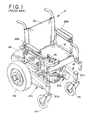
- Figure 1 is a perspective view of a power wheelchair of the type to which the subject invention may pertain.
- Figure 2 is an exploded perspective view of a conventional frame used in these types of wheelchairs.
- Figure 3 is an exploded perspective view of the components of the reversible, adjustable seat support assembly of the present invention.
- Figure 4 is an elevational view of a rear wheel drive power wheelchair with the seat at a 0° inclination.
- Figure 5 is an elevational view similar to Figure 3 but showing the seat at a 10° angle.
- Figure 6 shows an elevational view of a front wheel drive arrangement where the seat has been reversed from the position of Figures 4 and 5, and the seat is disposed at a 0° orientation.
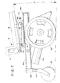
- Figure 7 is an elevational view similar to that of Figure 5 with the seat at an angle of approximately 10°.
- Figure 8 is a cross sectional view taken generally along the lines 8-8 in Figure 4.
- the wheelchair A includes a frame 10 to which enlarged diameter wheels 12 , also referred to as drive wheels, are operatively connected. Small diameter or driven wheels 14a, 14b are also operatively mounted to the frame. A seat 16 comprised of a seat portion 18 and a seat back 20 is mounted on the frame.
- the prior art power wheelchair of Figure 1 has a basic seat assembly, although it will be understood that the seat can be customized with special cushions, bolsters, pads, etc. , to meet the needs of the individual user.
- First and second motors 22a, 22b are mounted on the frame and operatively connected to the drive wheels through a gear box or other conventional structure.
- the motors are typically electrically operated and, thus, the wheelchair carries an on-board source of power such as batteries 24 .
- a control such as joy stick control 26 , is mounted on one of the arm rests 28 so that power is selectively provided to the left or right motor to selectively drive the wheels 12 in a forward or reverse direction.
- Details of a battery operated, joy stick controlled power wheelchair are generally known in the art so that further discussion herein is deemed unnecessary to a full and complete understanding of the present invention.
- powered rotation of the drive wheels steers the wheelchair since the driven wheels 14 are rotatably connected to the frame via caster assemblies 30 . Again, details of the caster assemblies are well known in the art so that further discussion is not warranted.
- first and second longitudinal frame members 40a, 40b extend fore and aft in the general direction of the drive and driven wheels.
- a cross or interconnecting frame member 42 is disposed substantially perpendicular and rigidly connected at opposite ends to the longitudinal frame members, for instance by welding or the like.
- Each longitudinal frame member has a first end 44 and a second end 46 .
- the first ends 44 terminate in a generally cylindrical housing that receives the caster assembly of the small diameter driven wheels 14a .
- a shock absorber assembly 48 (Figure 2) is preferably mounted adjacent the second ends 46 of the longitudinal frame members while the drive wheels are secured through a linkage assembly (unnumbered). Again, details of the structure shown in Figure 2 are set forth in greater detail in our U.S.A. Patent No. 5,575,348 so that familiarity with that structure is presumed and further description herein is deemed unnecessary.
- Figure 3 shows an exploded view of the seat support assembly, as well as Figures 4 and 5 which schematically illustrate a rear wheel drive version of a power wheelchair of the present invention.
- FIGs 4 and 5 schematically illustrate a rear wheel drive version of a power wheelchair of the present invention.
- like reference numerals will refer to like parts and the features of the present invention will be identified by new reference numerals.
- the enlarged diameter drive wheels 12 are more closely positioned adjacent the seat back 20 than the front of the seat portion 18.
- the small diameter driven wheels 14 are more closely located adjacent the front of the seat 18 than to the seat back 20 .
- the seat 16 includes rigid seat frame portions 60, 62 that are typically disposed beneath the cushion or upholstery portions of the wheelchair seat.
- seat frame member 60 is a rigid structure adapted to receive the seat cushion 18 while the angle bracket 62 is fixedly secured to the seat frame portion 60 in a generally perpendicular relation, and thus forms a part of the seat back 20 .
- a seat support assembly 64 ( Figure 4) interconnects the seat assembly 16 to the frame. It includes a first or upper seat support member 66 that is secured to an underside of the seat frame 60 .
- the seat support member 66 includes a pair of elongated slots 68, 70 generally disposed at opposite ends thereof. As will be more fully developed below, the elongated slots allow for desired angular adjustment of the seat relative to the frame.
- the seat support assembly includes a second or lower seat support member 76. It is adapted for connection to the frame, particularly the longitudinal members 40a, 40b in a manner to be described further below.
- the second seat support member has a generally triangular conformation that is mounted so that the higher end is disposed toward the first end 44 of the frame. Since the frame is preferably disposed at an angle, the triangular conformation provides that an upper surface of the second seat support is disposed in a generally horizontal plane.
- Openings 78 disposed at opposite ends of a second seat support member are adapted to receive a pin-type fastener, such as a nut and bolt 80 , that passes through the respective openings 68, 70 of the first seat support member.
- a pin-type fastener such as a nut and bolt 80
- the angular location of the seat may be adjusted.
- the fastener 80 is disposed adjacent an upper region of elongated opening 68
- fastener 82 is disposed adjacent a lower region of the elongated opening 70 .
- This attitude of the seat support assembly places the seat at a 0° orientation relative to the ground surface, i.e. , an upright seat position.
- FIGs 6 and 7 illustrate a front wheel drive wheelchair. Substantially, the same components are used in this front wheel drive version as were used in the rear wheel drive arrangement of Figures 4 and 5.
- the seat support assembly uses the identical two seat support members 66 and 76 , although the seat support members are reversed relative to one another. That is, the seat support member 66 remains secured to the seat frame member 60 in the same relationship so that the seat and seat support member 66 are merely reversed (i.e., rotated 180°) relative to the seat support member 76 and the frame.
- the fastener 80 is disposed adjacent the lower region of the elongated opening 70 while fastener 82 is disposed adjacent the upper region of the elongated opening 68 .
- a 10° adjustment of the seat angle can be accomplished in the front wheel drive version, again, by loosening the fasteners, re-orienting the seat support members (without disassembly), and tightening the fasteners at the desired new position.
- a 10° angle is defined between the seat 18 and the ground surface by positioning the fastener 82 adjacent the lower end of the elongated opening 68 while the fastener 80 is disposed adjacent the upper end of elongated opening 70.
- elongated openings and pins can be reversed, i.e., elongated openings provided on a seat support member secured to the frame while the fasteners 80, 82 could be provided on the seat support member secured to the seat, without substantially altering the seat adjustment function.
- each bar 84 includes threaded openings 86, 88 at opposite ends that allow the user to merely tighten the fasteners from a region easily accessible from outside of the wheelchair and without concern for holding a nut or the like in place at a region that would be difficult to access underneath the seat.
- FIG. 8 illustrates a cross-sectional view of one of the longitudinal frame members 40 , again, it being understood that the structure of the other longitudinal frame member is the same unless noted otherwise.
- the longitudinal frame member is a generally hollow rectangular structure having side walls 90, 92 and generally perpendicular upper and lower walls 94, 96 .
- the hollow rectangular tube construction provides the desired rigidity and strength required for the power wheelchair frame.
- channel 100 is defined by inverted Lshaped arms 102, 104 .
- the channel is integrally formed on an upper surface of the wall 94 of the longitudinal frame member. It will be appreciated, however, that the channel could also be defined by a separate components secured to the longitudinal frame members.
- the channel 100 has an opening 106 defined between the arms that preferably faces upwardly.
- the opening receives at least one fastener 108 , preferably a fastener at each end, extending from the second seat support member 76 .
- the fastener is a threaded nut and bolt assembly where the nut 110 is locked against rotation in the channel 100 while bolt 108 can be selectively tightened from above.
- the fore to aft location of the seat support assembly is fixed relative to the frame.
- the entire seat support assembly can be moved fore and aft along the longitudinal frame members, i.e., to various locations over the wheels 12, 14 as desired. Again, as briefly indicated above, this allows for alteration of the weight carried by the different wheels.
Landscapes
- Health & Medical Sciences (AREA)
- Life Sciences & Earth Sciences (AREA)
- Animal Behavior & Ethology (AREA)
- General Health & Medical Sciences (AREA)
- Public Health (AREA)
- Veterinary Medicine (AREA)
- Handcart (AREA)
- Automatic Cycles, And Cycles In General (AREA)
Applications Claiming Priority (2)
| Application Number | Priority Date | Filing Date | Title |
|---|---|---|---|
| US94424997A | 1997-10-06 | 1997-10-06 | |
| US944249 | 1997-10-06 |
Publications (2)
| Publication Number | Publication Date |
|---|---|
| EP0908167A2 true EP0908167A2 (fr) | 1999-04-14 |
| EP0908167A3 EP0908167A3 (fr) | 1999-12-08 |
Family
ID=25481064
Family Applications (1)
| Application Number | Title | Priority Date | Filing Date |
|---|---|---|---|
| EP98308025A Withdrawn EP0908167A3 (fr) | 1997-10-06 | 1998-10-01 | Siège réversible pour fauteuil roulant avec entraínement de roue avant et roue arrière ayant un règlage angulaire en continu |
Country Status (2)
| Country | Link |
|---|---|
| EP (1) | EP0908167A3 (fr) |
| CA (1) | CA2239706A1 (fr) |
Cited By (4)
| Publication number | Priority date | Publication date | Assignee | Title |
|---|---|---|---|---|
| WO2001003631A1 (fr) * | 1999-07-09 | 2001-01-18 | Invacare Deutschland Gmbh | Fauteuil roulant |
| WO2001089441A3 (fr) * | 2000-05-25 | 2002-04-11 | Movingpeople Net Internat B V | Chaise roulante |
| CN107568968A (zh) * | 2017-10-28 | 2018-01-12 | 泰州市明星五金配件厂 | 一种特殊的高端电动老板椅底座结构 |
| CN109199722A (zh) * | 2018-09-29 | 2019-01-15 | 浙江爱司米电气有限公司 | 一种快速拆装组合式助行机器人 |
Citations (1)
| Publication number | Priority date | Publication date | Assignee | Title |
|---|---|---|---|---|
| US5575348A (en) | 1994-04-15 | 1996-11-19 | Invacare Corporation | Powered wheelchair with adjustable center of gravity and independent suspension |
Family Cites Families (4)
| Publication number | Priority date | Publication date | Assignee | Title |
|---|---|---|---|---|
| DE3801874A1 (de) * | 1988-01-12 | 1989-07-20 | Ortopedia Gmbh | Elektrorollstuhl |
| WO1991017877A1 (fr) * | 1990-05-24 | 1991-11-28 | Medical Composite Technology | Chassis composite de fauteuil roulant et son procede de fabrication |
| WO1993000060A1 (fr) * | 1991-06-20 | 1993-01-07 | Tartan Rehab Limited | Siege coulissant pour fauteuil roulant |
| DE9310610U1 (de) * | 1993-07-17 | 1993-11-04 | Rundmund, Reinhold, 48317 Drensteinfurt | Rollstuhl |
-
1998
- 1998-06-05 CA CA 2239706 patent/CA2239706A1/fr not_active Abandoned
- 1998-10-01 EP EP98308025A patent/EP0908167A3/fr not_active Withdrawn
Patent Citations (1)
| Publication number | Priority date | Publication date | Assignee | Title |
|---|---|---|---|---|
| US5575348A (en) | 1994-04-15 | 1996-11-19 | Invacare Corporation | Powered wheelchair with adjustable center of gravity and independent suspension |
Cited By (5)
| Publication number | Priority date | Publication date | Assignee | Title |
|---|---|---|---|---|
| WO2001003631A1 (fr) * | 1999-07-09 | 2001-01-18 | Invacare Deutschland Gmbh | Fauteuil roulant |
| WO2001089441A3 (fr) * | 2000-05-25 | 2002-04-11 | Movingpeople Net Internat B V | Chaise roulante |
| CN107568968A (zh) * | 2017-10-28 | 2018-01-12 | 泰州市明星五金配件厂 | 一种特殊的高端电动老板椅底座结构 |
| CN109199722A (zh) * | 2018-09-29 | 2019-01-15 | 浙江爱司米电气有限公司 | 一种快速拆装组合式助行机器人 |
| CN109199722B (zh) * | 2018-09-29 | 2020-02-07 | 浙江爱司米电气有限公司 | 一种快速拆装组合式助行机器人 |
Also Published As
| Publication number | Publication date |
|---|---|
| CA2239706A1 (fr) | 1999-04-06 |
| EP0908167A3 (fr) | 1999-12-08 |
Similar Documents
| Publication | Publication Date | Title |
|---|---|---|
| US6003891A (en) | Tilt wheelchair with center of gravity compensation | |
| US4966379A (en) | Reclinable wheelchair | |
| EP0677285B1 (fr) | Fauteuil roulant motorisé avec centre de gravité réglable et avec suspension indépendant | |
| US5727802A (en) | Suspension wheelchair and wheelchair frame | |
| US7090240B2 (en) | Tiltable seating apparatus for wheelchair | |
| US6131679A (en) | Anti-tip assembly for power wheelchair | |
| US4892166A (en) | Motorized wheelchair assembly having coupling device | |
| US6932369B2 (en) | Wheelchair and structural elements therefore | |
| US5816614A (en) | Tiller assembly for personal mobility vehicles | |
| US4436320A (en) | Chassis for invalid wheelchairs | |
| US20100090437A1 (en) | Wheelchair Comprising A Foot Support | |
| EP0642429A1 (fr) | Fauteuil roulant electrique a ensemble moteur amovible----------. | |
| JP3433299B2 (ja) | 椅 子 | |
| DE20121824U1 (de) | Kleinfahrzeug, insbesondere Rollstuhl | |
| US20030122332A1 (en) | Wheel chair with monocoque-type body | |
| EP0941679A2 (fr) | Mécanisme de basculement et de glisse | |
| US6224156B1 (en) | Seat back recliner kit for wheelchair | |
| US20060181051A1 (en) | Active wheelchair | |
| EP0908167A2 (fr) | Siège réversible pour fauteuil roulant avec entraínement de roue avant et roue arrière ayant un règlage angulaire en continu | |
| US6250661B1 (en) | Tilt system for a powered wheelchair seat | |
| EP0761195B1 (fr) | Fauteuil roulant multifonctionnel | |
| EP1824724A2 (fr) | Fauteuil roulant pliable et plaque d'axe associee | |
| JP3072462B2 (ja) | 車椅子 | |
| WO1997031606A1 (fr) | Cadre lateral pour fauteuil roulant, et fauteuil roulant le comportant | |
| JP2553361Y2 (ja) | 特殊車輛用サスペンションシート |
Legal Events
| Date | Code | Title | Description |
|---|---|---|---|
| PUAI | Public reference made under article 153(3) epc to a published international application that has entered the european phase |
Free format text: ORIGINAL CODE: 0009012 |
|
| AK | Designated contracting states |
Kind code of ref document: A2 Designated state(s): AT BE CH CY DE DK ES FI FR GB GR IE IT LI LU MC NL PT SE |
|
| AX | Request for extension of the european patent |
Free format text: AL;LT;LV;MK;RO;SI |
|
| PUAL | Search report despatched |
Free format text: ORIGINAL CODE: 0009013 |
|
| AK | Designated contracting states |
Kind code of ref document: A3 Designated state(s): AT BE CH CY DE DK ES FI FR GB GR IE IT LI LU MC NL PT SE |
|
| AX | Request for extension of the european patent |
Free format text: AL;LT;LV;MK;RO;SI |
|
| AKX | Designation fees paid | ||
| REG | Reference to a national code |
Ref country code: DE Ref legal event code: 8566 |
|
| STAA | Information on the status of an ep patent application or granted ep patent |
Free format text: STATUS: THE APPLICATION IS DEEMED TO BE WITHDRAWN |
|
| 18D | Application deemed to be withdrawn |
Effective date: 20000609 |