EP0908202B1 - Schuhrückhaltevorrichtung auf einem Snowboard, insbesondere einem Ski - Google Patents
Schuhrückhaltevorrichtung auf einem Snowboard, insbesondere einem Ski Download PDFInfo
- Publication number
- EP0908202B1 EP0908202B1 EP98810928A EP98810928A EP0908202B1 EP 0908202 B1 EP0908202 B1 EP 0908202B1 EP 98810928 A EP98810928 A EP 98810928A EP 98810928 A EP98810928 A EP 98810928A EP 0908202 B1 EP0908202 B1 EP 0908202B1
- Authority
- EP
- European Patent Office
- Prior art keywords
- lock
- rail
- lever
- slide
- flanges
- Prior art date
- Legal status (The legal status is an assumption and is not a legal conclusion. Google has not performed a legal analysis and makes no representation as to the accuracy of the status listed.)
- Expired - Lifetime
Links
Images
Classifications
-
- A—HUMAN NECESSITIES
- A63—SPORTS; GAMES; AMUSEMENTS
- A63C—SKATES; SKIS; ROLLER SKATES; DESIGN OR LAYOUT OF COURTS, RINKS OR THE LIKE
- A63C9/00—Ski bindings
- A63C9/005—Ski bindings with means for adjusting the position of a shoe holder or of the complete binding relative to the ski
Definitions
- the present invention relates to a retaining device a shoe on a gliding board, for example a ski, comprising a body slidably mounted on a slide, a lock articulated on said body and immobilizing this body on the slide, latch and slide being, for this purpose, provided with means of mutual bonding along the central region of the slide, means consisting, on the one hand, of teeth and, on the other hand, of housings in which the teeth are engaged, the lock being provided with a lever unlocking extending above the slide, in direction from outside the body, this lever allowing manually release the slide lock by engaging a finger under the lever.
- Such a device is known from the utility model German 295 20 845.
- the teeth of the lock engage in a rack of the slide and the lever of the latch extends widely above the slide so as to allow the lock to be detached and rack by lifting the lever without help tool.
- the lever extends between two side walls body parallels to protect the lock against an unwanted unlocking due to a shock on its lever, for example shock when loading skis on a gondola. Lock security requires therefore a particular fixing body.
- the object of the present invention is to produce a lock having its own security means so that it can be used in fixing bodies existing.
- the retaining device according to the invention is characterized in that the unlocking lever has two side wings extending towards the down to the slide on either side of the region center of the slide.
- the release lever can be a part separate from the lock or come from a room with the lock.
- Seen from behind the unlocking lever present therefore an inverted U-shaped profile constituting a housing into which a finger can be easily inserted for lift the lever, this profile being however narrow enough to prevent unlocking longed for.
- the protective effect can also be increased by tilting the side faces the release lever and on the outside edge of the wings of the profile. The advantage of such an inclination to generate, in the event of an impact, forces tending to press the latch against the slide.
- the lock Taking into account the dimensional tolerances allowed in the manufacture of ski binding components and necessary for manufacturing at a reasonable cost, the lock inevitably presents some play in the slide. Downhill, this game results in slight displacements accompanied by noises which can create a feeling of instability.
- the lock according to the invention allows you to reduce or even delete this game. if the release lever came in one piece with the lock or if it is mounted without play on the lock and if we admit that the transverse play between the wings of the lock lever and the slide is equal or lower than the hanging play, the side wings of the release lever being located at a distance from the area of attachment of the bolt to the slide according to the longitudinal direction of the slide, they have for effect of significantly reducing or even eliminating the hanging game.
- the slide has two longitudinal grooves located on each side of the central region and the wings of the lock lever are parallel and engaged in said grooves, the width of these grooves being substantially equal to the thickness of the wings of the lock.
- the joint of the lock in the body of the device retention is ensured by two lateral tabs of the lock by which the lock is retained and articulated on the body.
- the retainer includes a spring recoil resting on one end of the angled lock upwards
- this bent end presents itself an elbow approximately halfway up so that the recoil spring, essentially rests against an inclined face towards the lever of the lock so as to create a couple pressing the lock against the slide in the hanging area.
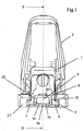
- Figure 1 is an end view, from the rear, of a fastening element for the heel of a shoe or heel.
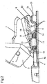
- Figure 2 is an axial sectional view along II-II of Figure 1, that is to say in the plane of symmetry.
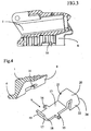
- Figure 3 is a sectional view along II-II of the body fixing alone, i.e. without any other component of the heel piece.
- Figure 4 is a partial perspective view of the body of the heel piece and the bolt, illustrating the joint of the lock on the body.
- the heel piece shown is essentially consisting of a fixing body 1 and a gripper 2 articulated around an axis 3 on the body 1 and solicited by a trigger spring contained in the body 1.
- the body 1 is mounted on a slide 4 consisting of a profile metallic with side edges curved towards the interior and in which the body 1 is engaged by two heels 5 and 6.
- the slide 4 is fixed by means screws on the ski or on a raised plate. It is surrounded by a covering 27 in material plastic.
- Slide 4 presents, in its part central, a raised strip 4a in which are formed two rows of holes 7. This strip presents, naturally, a trapezoidal profile due to stamping.
- the body 1 has a clearance 8 in the form of a tunnel in which is mounted a lock 9 provided with teeth 10 engaging in certain holes 7 and a recoil spring 11 working in compression between the bottom 12 of the clearance 8 and the lock 9.
- the shape of the lock 9 is clearly visible in the figure 4. It consists of a stamped metal part having a flat base 13 under which are formed teeth 10 and which has two lateral tabs 14 and 15 used for the articulation of the lock 9 in the body 1.
- the body 1 presents, in the interior side faces of clearance 8, hanging grooves 16 in which come engage lugs 14 and 15 and the bottom of which serves bearings at legs 14 and 15.
- the latch 9 On the side of spring 11, the latch 9 has a bent part upwards.
- This bent part itself has a bend 17, such so that the bent part forms a dihedral 18, 19 substantially symmetrical relative to a plane horizontal and whose edge is located a little above of the axis of the spring 11, so that this spring rests on the elbow 17, so as to create, around the hinge pin 9, a torque which has tendency to turn lock 9 clockwise clockwise, figure 2, i.e. press its toothed part against the slide 4 and by therefore keep the lock in position locked.
- the lever 9 Towards the back of the heel, i.e. towards the outside of the body 1, the lever 9 has a raised portion 20 extending above of the slide and forming a lever for the release teeth 10 of their housings 7.
- This lever 20 is provided with two lateral wings 21 and 22 extending towards the bottom, parallel to the longitudinal axis of the slide. These wings 21, 22 are slightly inclined outward so that lever 20 and its wings 21 and 22 form a clearly trapezoidal profile visible in Figure 1.
- the spacing of the wings 21 and 22 at their root is less than the width of the part raised central 4a of the slide 4 while the spacing of the wings 21 and 22 at their ends is slightly greater than the width of the upper face of the central zone 4a.
- the wings 21 and 22 are distant from teeth 10, that is to say from the latching area of the lock to the slide.
- the outer edge, relative to the body 1, 23, 24, wings 21 and 22 is tilted from bottom to top in the direction of teeth 10, i.e. the area hooking, so that a shock on these edges, for example a edge of a ski or when loading on a cable car, does not risk lift lever 20 and therefore unlock the lock 9, but has, on the contrary, tendency to press the lock against the slide.
- Slide 4 may not have a zone raised central.
- the wings 22 and 23 also have the effect of preventing accidental actuation of the lock by impact side of an object.
- the inclination of the wings also the effect, in the event of a side impact, of obtaining a force which tends to press the wings against the slide.
- the slide could have any other profile, for example example a profile as shown in the model utility DE 295 20 845.
- the slide could have a rack, for example a rack such as shown in the utility model DE 295 20 845.
- the lock could have holes cooperating with teeth or a slide rack.
- the device according to the invention is of course applicable to a fastener on the front of the shoe,
- the release lever could be a part separate from the lock, fixed on the lock or articulated on the latch and bearing on the slide.
Landscapes
- Footwear And Its Accessory, Manufacturing Method And Apparatuses (AREA)
- Fittings On The Vehicle Exterior For Carrying Loads, And Devices For Holding Or Mounting Articles (AREA)
Claims (11)
- Haltevorrichtung zum Halten eines Schuhs auf einem Gleitbrett mit einem auf einer Führungsschiene (4) gleitend montierten Gehäuse (1), einem Riegel (9), der an dem erwähnten Gehäuse (1) angelenkt ist und dieses auf der Führungsschiene (4) festhält, wobei Riegel (9) und Führungsschiene (4) zu diesem Zwecke mit Mitteln zum gegenseitigen Festhaken längs des zentralen Bereichs (4a) der Führungsschiene (4) versehen sind und diese Mittel einerseits aus Zähnen (10) und andererseits aus Vertiefungen (7) bestehen, in welche die Zähne (10) eingreifen, und wobei der Riegel (9) mit einem Entriegelungshebel (20) versehen ist, der sich über der Führungsschiene (4) in Richtung auf die Aussenseite des Gehäuses (1) erstreckt und die manuelle Freigabe des Riegels (9) der Führungsschiene (4) erlaubt, indem man mit einem Finger unter diesen Hebel (20) greift, dadurch gekennzeichnet, dass der erwähnte Hebel (20) mit zwei Seitenwänden (21, 22) versehen ist, die sich beiderseits des zentralen Bereichs (4a) der Führungsschiene (4) nach unten bis zu dieser Führungsschiene (4) erstrecken.
- Vorrichtung nach Anspruch 1, dadurch gekennzeichnet, dass die Seitenwände (21, 22) des Entriegelungshebels (20) seitlich durch die Führungsschiene (4) gehalten werden und in Längsrichtung im Abstand von der Zone liegen, in welcher der Riegel (9) auf der Führungsschiene (4) festhakbar ist.
- Vorrichtung nach Anspruch 2, bei welcher die erwähnten Vertiefungen (7) in einem hochliegenden Bereich (4a) der Gleitschiene (4) angebracht sind, dadurch gekennzeichnet, dass sich die Seitenwände (21, 22) des Entriegelungshebels (20) mit ihren Innenflächen auf den Seiten des hochliegenden zentralen Bereichs (4a) der Führungsschiene (4) abstützen.
- Vorrichtung nach Anspruch 3, dadurch gekennzeichnet, dass die Seitenwände (21, 22) des Entriegelungshebels (20) geneigt sind und nach unten divergieren.
- Vorrichtung nach Anspruch 2, dadurch gekennzeichnet, dass die Führungsschiene (4) zwei beiderseits des zentralen Bereichs (4a) liegende Längsnuten hat und dass die Seitenwände (21, 22) des Entriegelungshebels (20) parallel sind und in diese Nuten eingreifen, deren Breite im wesentlichen gleich der Dicke der Seitenwände (21, 22) des Riegels (9) ist.
- Vorrichtung nach einem der Ansprüche 1 bis 5, dadurch gekennzeichnet, dass der äussere endseitige Rand (23, 24) der Seitenwände (21, 22) von unten nach oben in Richtung auf die Zone geneigt ist, in welcher der Riegel (9) auf der Führungsschiene (4) festhakbar ist.
- Vorrichtung nach einem der Ansprüche 1 bis 6, dadurch gekennzeichnet, dass der Riegel (9) zwei seitliche Ansätze (14; 15) hat, durch die er am Gehäuse (1) gehalten und angelenkt ist.
- Vorrichtung nach einem der Ansprüche 1 bis 7, mit einer Rückschubfeder (11), die sich auf dem dem Hebel (20) abgewandten, nach oben abgewinkelten Ende des Riegels (9) abstützt, dadurch gekennzeichnet, dass dieses abgewinkelte Ende auf ungefähr halber Höhe einen Knick (17) hat, auf dem sich die Rückschubfeder abstützt, um den Riegel (9) gegen die Führungsschiene (4) zu drücken.
- Vorrichtung nach einem der Ansprüche 1 bis 8, dadurch gekennzeichnet, dass der Entriegelungshebel (20) und der Riegel (9) einteilig ausgebildet sind.
- Vorrichtung nach einem der Ansprüche 1 bis 8, dadurch gekennzeichnet, dass der Entriegelungshebel (20) aus einem vom Riegel (9) getrennte Teil besteht.
- Vorrichtung nach Anspruch 10, dadurch gekennzeichnet, dass der Entriegelungshebel (20) selber auf dem Riegel (9) angelenkt ist.
Applications Claiming Priority (2)
| Application Number | Priority Date | Filing Date | Title |
|---|---|---|---|
| FR9712636 | 1997-10-06 | ||
| FR9712636A FR2769237B1 (fr) | 1997-10-06 | 1997-10-06 | Dispositif de retenue d'une chaussure sur une planche de glisse, en particulier un ski |
Publications (2)
| Publication Number | Publication Date |
|---|---|
| EP0908202A1 EP0908202A1 (de) | 1999-04-14 |
| EP0908202B1 true EP0908202B1 (de) | 2004-01-28 |
Family
ID=9512039
Family Applications (1)
| Application Number | Title | Priority Date | Filing Date |
|---|---|---|---|
| EP98810928A Expired - Lifetime EP0908202B1 (de) | 1997-10-06 | 1998-09-17 | Schuhrückhaltevorrichtung auf einem Snowboard, insbesondere einem Ski |
Country Status (5)
| Country | Link |
|---|---|
| US (1) | US6220619B1 (de) |
| EP (1) | EP0908202B1 (de) |
| AT (1) | ATE258455T1 (de) |
| DE (1) | DE69821306T2 (de) |
| FR (1) | FR2769237B1 (de) |
Families Citing this family (3)
| Publication number | Priority date | Publication date | Assignee | Title |
|---|---|---|---|---|
| FR2833851B1 (fr) | 2001-12-20 | 2004-02-27 | Look Fixations Sa | Dispositif de reglage de la position d'une fixation de chaussure sur une planche de glisse |
| FR2881058B1 (fr) * | 2005-01-25 | 2007-04-20 | Skis Rossignol Sa Sa | Dispositif de reglage a engrenage de la durete d'une fixation |
| CN103492046B (zh) | 2011-01-20 | 2015-08-26 | 沙特阿拉伯石油公司 | 将废热用于co2的车上回收和存储的可逆固体吸附方法和系统 |
Family Cites Families (17)
| Publication number | Priority date | Publication date | Assignee | Title |
|---|---|---|---|---|
| AT276180B (de) * | 1965-12-20 | 1969-11-10 | Smolka & Co Wiener Metall | Skibindungselement |
| CH509812A (de) * | 1969-05-02 | 1971-07-15 | Gertsch Ernst | Längsverstellbare Absatzklemmvorrichtung an Skibindung |
| FR2368974A1 (fr) * | 1976-11-02 | 1978-05-26 | Beyl Jean Joseph Alfred | Dispositif de fixation de ski |
| AT367642B (de) * | 1980-06-12 | 1982-07-26 | Tyrolia Freizeitgeraete | Verstelleinrichtung fuer einen skibindungsteil |
| AT376572B (de) * | 1980-11-14 | 1984-12-10 | Tyrolia Freizeitgeraete | Verstellvorrichtung |
| AT371348B (de) * | 1981-06-12 | 1983-06-27 | Tyrolia Freizeitgeraete | Vorrichtung zur laengsverstellung von skibindungs- teilen |
| AT387151B (de) * | 1987-03-13 | 1988-12-12 | Tyrolia Freizeitgeraete | Sicherheitsskibindung |
| FR2614545B1 (fr) * | 1987-04-30 | 1989-06-16 | Salomon Sa | Fixation de securite pour ski |
| FR2638653B1 (fr) * | 1988-11-07 | 1991-01-25 | Salomon Sa | Fixation de securite pour ski |
| DE58904223D1 (de) * | 1989-04-25 | 1993-06-03 | Look Sa | Sicherheitsskibindung. |
| CH676205A5 (de) * | 1989-05-04 | 1990-12-28 | Urs P Meyer | |
| FR2672506B1 (fr) * | 1991-02-08 | 1993-04-30 | Salomon Sa | Fixation de securite pour ski. |
| FR2684889B1 (fr) * | 1991-12-13 | 1994-02-04 | Salomon Sa | Piece d'interface pour la glissiere d'un element de fixation, notamment de fixation alpine. |
| AT398701B (de) * | 1992-10-23 | 1995-01-25 | Tyrolia Freizeitgeraete | Skibindung mit einem fersenteil |
| DE19507267A1 (de) | 1995-03-03 | 1996-09-05 | Marker Deutschland Gmbh | Vorrichtung zur Längsverstellung eines Skibindungsteiles |
| FR2735699B1 (fr) * | 1995-06-22 | 1997-09-05 | Salomon Sa | Element de retenue d'une chaussure sur un ski |
| US5913532A (en) * | 1996-12-18 | 1999-06-22 | Look Fixations Sa | Ski binding |
-
1997
- 1997-10-06 FR FR9712636A patent/FR2769237B1/fr not_active Expired - Fee Related
-
1998
- 1998-09-17 AT AT98810928T patent/ATE258455T1/de not_active IP Right Cessation
- 1998-09-17 DE DE69821306T patent/DE69821306T2/de not_active Expired - Lifetime
- 1998-09-17 EP EP98810928A patent/EP0908202B1/de not_active Expired - Lifetime
- 1998-10-02 US US09/165,910 patent/US6220619B1/en not_active Expired - Lifetime
Also Published As
| Publication number | Publication date |
|---|---|
| FR2769237B1 (fr) | 1999-12-10 |
| US6220619B1 (en) | 2001-04-24 |
| DE69821306T2 (de) | 2004-10-28 |
| FR2769237A1 (fr) | 1999-04-09 |
| DE69821306D1 (de) | 2004-03-04 |
| ATE258455T1 (de) | 2004-02-15 |
| EP0908202A1 (de) | 1999-04-14 |
Similar Documents
| Publication | Publication Date | Title |
|---|---|---|
| EP0086908B1 (de) | Skischuh | |
| EP0659364B1 (de) | Spangenfassung | |
| EP0296898A1 (de) | Schuhbefestigungsvorrichtung an einem Fahrradpedal | |
| FR2705248A1 (fr) | Dispositif de retenue d'une chaussure sur une planche de glisse. | |
| FR2631905A1 (fr) | Dispositif d'ancrage | |
| CA2706758A1 (fr) | Chaussure pour ski | |
| CH636529A5 (fr) | Fixation de securite de ski. | |
| FR2635465A1 (fr) | Fixation de securite pour ski | |
| EP1106218B1 (de) | Langlaufski | |
| FR2739572A1 (fr) | Embase de fixation de ski reglable longitudinalement | |
| FR2619317A1 (fr) | Dispositif de fixation d'une tige ou d'un dessus de tige dans une chaussure de ski | |
| EP0908202B1 (de) | Schuhrückhaltevorrichtung auf einem Snowboard, insbesondere einem Ski | |
| EP0965369B1 (de) | Bindungselement fur einen alpinen Ski mit abnehmbarer Bremse | |
| CH633723A5 (fr) | Fixation de securite pour ski. | |
| FR2761422A1 (fr) | Dispositif de fixation d'un element quelconque, tel qu'une poignee, sur une paroi | |
| FR2651145A1 (fr) | Fixation de securite pour ski. | |
| EP1321172B1 (de) | Vorrichtung zur Einstellung der Position einer Snowboardbindung | |
| EP1025881B1 (de) | Skibremse | |
| FR2742997A1 (fr) | Perfectionnement pour dispositif de retenue d'une chaussure a une planche de glisse pour neige | |
| CH677432A5 (de) | ||
| EP1731202A1 (de) | In der Breite verstellbare Bremsvorrichtung für Gleitbrett | |
| FR2652508A1 (fr) | Dispositif d'appui, sur un ski, de la partie anterieure de la semelle d'une chaussure. | |
| FR2777473A1 (fr) | Dispositif interface entre un ski et des elements de retenue d'une chaussure pour regler rapidement et facilement la position longitudinale des elements de retenue avant et arriere sur un ski | |
| FR2782653A1 (fr) | Butee demontable pour corps coulissant de fixation de ski | |
| FR2811904A1 (fr) | Dispositif d'orientation angulaire d'une chaussure pour planche de glisse ou de roulage |
Legal Events
| Date | Code | Title | Description |
|---|---|---|---|
| PUAI | Public reference made under article 153(3) epc to a published international application that has entered the european phase |
Free format text: ORIGINAL CODE: 0009012 |
|
| 17P | Request for examination filed |
Effective date: 19990118 |
|
| AK | Designated contracting states |
Kind code of ref document: A1 Designated state(s): AT DE |
|
| AX | Request for extension of the european patent |
Free format text: AL;LT;LV;MK;RO;SI |
|
| AKX | Designation fees paid |
Free format text: AT DE |
|
| GRAP | Despatch of communication of intention to grant a patent |
Free format text: ORIGINAL CODE: EPIDOSNIGR1 |
|
| GRAS | Grant fee paid |
Free format text: ORIGINAL CODE: EPIDOSNIGR3 |
|
| GRAA | (expected) grant |
Free format text: ORIGINAL CODE: 0009210 |
|
| AK | Designated contracting states |
Kind code of ref document: B1 Designated state(s): AT DE |
|
| REF | Corresponds to: |
Ref document number: 69821306 Country of ref document: DE Date of ref document: 20040304 Kind code of ref document: P |
|
| PLBE | No opposition filed within time limit |
Free format text: ORIGINAL CODE: 0009261 |
|
| STAA | Information on the status of an ep patent application or granted ep patent |
Free format text: STATUS: NO OPPOSITION FILED WITHIN TIME LIMIT |
|
| 26N | No opposition filed |
Effective date: 20041029 |
|
| PGFP | Annual fee paid to national office [announced via postgrant information from national office to epo] |
Ref country code: AT Payment date: 20050913 Year of fee payment: 8 |
|
| PG25 | Lapsed in a contracting state [announced via postgrant information from national office to epo] |
Ref country code: AT Free format text: LAPSE BECAUSE OF NON-PAYMENT OF DUE FEES Effective date: 20060917 |
|
| PGFP | Annual fee paid to national office [announced via postgrant information from national office to epo] |
Ref country code: DE Payment date: 20160928 Year of fee payment: 19 |
|
| REG | Reference to a national code |
Ref country code: DE Ref legal event code: R119 Ref document number: 69821306 Country of ref document: DE |
|
| PG25 | Lapsed in a contracting state [announced via postgrant information from national office to epo] |
Ref country code: DE Free format text: LAPSE BECAUSE OF NON-PAYMENT OF DUE FEES Effective date: 20180404 |