EP0908209B1 - Einspuriger Rollschuh - Google Patents
Einspuriger Rollschuh Download PDFInfo
- Publication number
- EP0908209B1 EP0908209B1 EP98118750A EP98118750A EP0908209B1 EP 0908209 B1 EP0908209 B1 EP 0908209B1 EP 98118750 A EP98118750 A EP 98118750A EP 98118750 A EP98118750 A EP 98118750A EP 0908209 B1 EP0908209 B1 EP 0908209B1
- Authority
- EP
- European Patent Office
- Prior art keywords
- frame
- shoe
- base
- skate according
- wings
- Prior art date
- Legal status (The legal status is an assumption and is not a legal conclusion. Google has not performed a legal analysis and makes no representation as to the accuracy of the status listed.)
- Expired - Lifetime
Links
- 230000000284 resting effect Effects 0.000 claims description 5
- 230000004913 activation Effects 0.000 claims description 3
- 230000009849 deactivation Effects 0.000 claims description 3
- 239000004033 plastic Substances 0.000 claims description 3
- 229920003023 plastic Polymers 0.000 claims description 3
- 230000006835 compression Effects 0.000 claims description 2
- 238000007906 compression Methods 0.000 claims description 2
- 230000008878 coupling Effects 0.000 description 3
- 238000010168 coupling process Methods 0.000 description 3
- 238000005859 coupling reaction Methods 0.000 description 3
- 239000000463 material Substances 0.000 description 2
- 241000229970 Hypnos Species 0.000 description 1
- 230000009471 action Effects 0.000 description 1
- 230000003213 activating effect Effects 0.000 description 1
- 230000000670 limiting effect Effects 0.000 description 1
- 230000004048 modification Effects 0.000 description 1
- 238000012986 modification Methods 0.000 description 1
Images


Classifications
-
- A—HUMAN NECESSITIES
- A63—SPORTS; GAMES; AMUSEMENTS
- A63C—SKATES; SKIS; ROLLER SKATES; DESIGN OR LAYOUT OF COURTS, RINKS OR THE LIKE
- A63C17/00—Roller skates; Skate-boards
- A63C17/04—Roller skates; Skate-boards with wheels arranged otherwise than in two pairs
- A63C17/06—Roller skates; Skate-boards with wheels arranged otherwise than in two pairs single-track type
-
- A—HUMAN NECESSITIES
- A63—SPORTS; GAMES; AMUSEMENTS
- A63C—SKATES; SKIS; ROLLER SKATES; DESIGN OR LAYOUT OF COURTS, RINKS OR THE LIKE
- A63C17/00—Roller skates; Skate-boards
- A63C17/20—Roller skates; Skate-boards with fixable wheels permitting the skates to be used for walking
-
- A—HUMAN NECESSITIES
- A63—SPORTS; GAMES; AMUSEMENTS
- A63C—SKATES; SKIS; ROLLER SKATES; DESIGN OR LAYOUT OF COURTS, RINKS OR THE LIKE
- A63C17/00—Roller skates; Skate-boards
- A63C2017/0053—Roller skates; Skate-boards with foot plate quick release or shoe binding
Definitions
- the present invention relates to an inline skate.
- Conventional skates are constituted by a shoe, produced for example by injecting plastic material, which is associated with a usually U-shaped frame supporting a plurality of inline wheels.
- skates The problem that has arisen regarding the use of said skates is the fact that they can be used only for skating, thus forcing the user to remove, before putting on the skates, the shoes that he usually uses for normal walking.
- An engagement element such as a pin, is provided at the frame for a grip element which is constituted by a blade arranged below the sole of the shoe, which is locked with respect to the frame by virtue of the presence, to the rear of said frame, of an H-shaped rod whose ends are transversely pivoted to the frame at one end and are transversely pivoted, at the other end, to a lever which interacts with a suitable element associated with the shoe.
- the frame must be supported by the user.
- the aim of the present invention is to solve the above-described problems, eliminating the drawbacks of the cited prior art, by providing a skate which comprises a frame and a shoe which is detachably associated therewith and in which said connection or disconnection of the shoe with respect to the frame can be performed easily and quickly by the user.
- An important object of the present invention is to provide a skate in which the user can optimally position the shoe on the frame while standing.
- Another important object of the present invention is to provide a skate in which said coupling and uncoupling between the shoe and the frame can occur also if the resting surface is inclined, such as in a downhill road.
- Another important object of the present invention is to provide a skate which does not require the user to perform particular movements or physical efforts to achieve optimum positioning of the shoe on the frame.
- Another object of the present invention is to provide a skate which is structurally simple, reliable and safe in use.
- a skate comprising a frame provided with means for detachable connection to a shoe and with which wheels are associated, characterized in that it comprises a device for temporarily supporting said frame in a stable position which can be deactivated when said shoe is coupled to said frame.
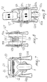
- 1 designates a skate comprising a shoe 2, for example of the type preferably comprising a soft upper 3 below which a sole 4 is associated.
- Said sole rests, in the particular illustrated embodiment, below the toe region 5 and the heel region 6, at a first base 7 and at a second base 8 of a frame 9 which forms a pair of first wings 10a and 10b between which two or more wheels 11 are freely pivoted and are thus arranged mutually in line.
- connection device includes a lever 12, which has two facing free ends 13a and 13b pivoted to the rear of the second base 8 and cooperates with a torsion bar or spring 14 which is suitable to force said lever 12 toward the region 15 of the heel of the shoe and to engage at a suitable base 16 formed to the rear of the sole 4.
- the reference numeral 19 designates the device for temporarily supporting the frame 9 in a stable position: said device is constituted, in the particular embodiment shown, by a U-shaped element which forms a third base 20 and a pair of second wings 21a and 21b which are laterally adjacent to the first wings 10a and 10b of the frame 9 and are pivoted transversely thereto by means of a suitable pivot 22 proximate to the second base 8.
- a sleeve 23 is rotatably associated with the third base 20 coaxially thereto, while suitable fittings 24a and 24b, made of plastics or rubber, are associated with the free ends of the second wings 21a and 21b.
- suitable fittings 24a and 24b made of plastics or rubber, are associated with the free ends of the second wings 21a and 21b.
- the shape and length of said fittings allow optimum resting on the ground in the regions adjacent to one of said wheels.
- the device 19 is further constituted by a spring 25 which is arranged coaxially to said pivot 22 and the ends whereof are rigidly coupled at said second wings 21a and 21b.
- the spring is suitable to force a clockwise rotation of the device, so as to make the fittings 24a and 24b interact with the ground when the shoe is not associated with the frame.
- a seat 26 is further formed at the second base 8 and is suitable to accommodate the sleeve 23 when the shoe is associated with the frame 9.
- a skate having been provided which comprises a device which allows to keep the frame in a stable vertical position with respect to the ground when the shoe is not associated therewith: this allows the user to quickly and easily associate the shoe with the frame while standing upright, since said frame is arranged in the optimum condition for resting the shoe thereon.
- the temporary support device When the user disengages the shoe from the frame, the temporary support device is automatically activated into the stable position of the frame without any specific intervention on the part of the user.
- the illustrated embodiment further allows the user to remove the shoe from the frame also in particularly demanding conditions, such as for example if the road slopes downhill.
- the materials and the dimensions that constitute the individual components of the device and the structure may also be the most pertinent according to specific requirements.
- the tips of the fittings 24a and 24b can have a conical shape or can in any case have a base whose dimensions allow to achieve optimum frame support.
- the location of the device can be varied according to specific requirements.
- the skate can further provide for the use of even more than one temporary support device, variously applied at one of the parts that constitute the frame.
- Figs. 7, 8 and 9 illustrate a second embodiment for a skate 101 which is again constituted by a shoe 102 composed of an upper 103 below which a sole 104 is associated.
- the sole 104 can be arranged, at the tip and heel regions, on a first base 107 and on a second base 108 of a frame 109 between the first wings 110a and 110b whereof suitable wheels 111 are freely pivoted.
- the means for detachable connection between the shoe 102 and the frame 109 are constituted by a substantially L-shaped lever 112, one end of which interacts with an abutment 116 formed to the rear of the sole 104.
- the lever 112 is articulated to a tension member such as a cable 127 which is associated at a plate 128 associated with the frame 109 so that it can slide along the longitudinal axis.
- a tension member such as a cable 127 which is associated at a plate 128 associated with the frame 109 so that it can slide along the longitudinal axis.
- Said plate 128 is forced to slide toward the region 105 of the tip of the shoe by a suitable cylindrical helical compression spring 125, which is interposed between a first tooth or seat 129 and a second tooth or seat 130 formed respectively in said plate 128 and in said frame 109 in the region of the second base 108.
- Slots 131 are formed at the lateral surfaces of the plate 128, preferably lie on a plane which is parallel to the plane of the first wings 110a and 110b and along the same transverse axis; the axis of said slots is arranged at right angles to the ground.
- the third base 120 of the device 119 for temporarily supporting the frame in a stable position when the shoe is not associated therewith is accommodated within said slots 131.
- the device 119 comprises second wings 121a and 121b which are arranged outside the first wings 110a and 110b of the frame 109 and are pivoted thereto by means of a suitable pivot 122.
- Suitable fittings 124a and 124b are associated with the tips of the second wings 121a and 121b and interact directly with the ground when the shoe is not associated with the frame.
- the plate 128 When the user associates the shoe with the frame, and therefore when locking occurs by means of the lever 112, the plate 128 is pulled and slides backward, simultaneously loading the spring 125 and producing, by virtue of the presence of the slots 131, the rotation of the device 119 and the lifting of the fittings 124a and 124b.
- the device can, for example, be of a telescopic type in which one end is associated with said frame and the other suitably shaped end interacts with the ground.
Landscapes
- Footwear And Its Accessory, Manufacturing Method And Apparatuses (AREA)
- Motorcycle And Bicycle Frame (AREA)
Claims (16)
- Rollschuh, umfassend: einen Rahmen (9), der mit einem Mittel zur lösbaren Verbindung mit einem Schuh (2) versehen ist, und mit dem Räder (11) verbunden sind, dadurch gekennzeichnet, dass er eine Einriehtung (19) zum vorübergehenden Halten des Rahmens in einer stabilen Position umfasst, welche deaktiviert werden kann, wenn der Schuh mit dem Rahmen verbunden wird.
- Rollschuh nach Anspruch 1, dadurch gekennzeichnet, dass die Einrichtung (19) eine erste zurückgezogene Position, die eine nicht ausbalancierte Position für den Rahmen (9) bildet und eine zweite stabil ausbalancierte Position für den Rahmen (9) aufweist.
- Rollschuh nach Anspruch 2, umfassend einen Schuh, der ein weiches Oberleder (3) aufweist, unterhalb dessen eine Sohle (4) angebracht ist, wobei die Sohle unterhalb der Zehen- und Fersenbereiche (5, 6) auf einem ersten Sockel (7) und einem zweiten Sockel (8) des Rahmens (9) aufliegt, der zwei erste Flügel (10a, 10b) bildet, zwischen denen sich zwei oder mehr miteinander in Reihe befindliche Räder (11) frei drehen lassen, dadurch gekennzeichnet, dass die Einrichtung (19) zum vorübergehenden Halten durch ein U-förmiges Element, das einen dritten Sockel (20) bildet, und zwei zweite Flügel (21a, 21b) gebildet wird, die seitlich am die ersten Flügel (10a, 10b) des Rahmens (9) angrenzen und sich dorthin mittels einer in der Nähe des zweiten Sockels (8) befindlichen Schwenkachse (22) schwenken lassen.
- Rollschuh nach Anspruch 3, dadurch gekennzeichnet, dass eine Hülse (23) drehbar und koaxial mit dem dritten Sockel (20) verbunden ist, während Passstücke (24a, 24b) mit den freien Enden der zweiten Flügel (21a, 21b) verbunden sind, wobei die Passstücke aus Kunststoff oder Gummi bestehen und eine Länge und Form aufweisen, die ein optimales Aufliegen auf dem Boden in den Bereichen ermöglichen, die an eines der Räder angrenzen.
- Rollschuh nach Anspruch 3 oder 4, dadurch gekennzeichnet, dass die Einrichtung weiter eine Feder (25) umfasst, die koaxial mit der Schwenkachse (22) angeordnet ist und deren Enden starr mit den zweiten Flügeln (21a, 21b) verbunden sind, wobei die Feder geeignet ist, eine Drehung der Einrichtung im Uhrzeigersinn zu erzwingen, um die zweiten Flügel oder die Passstücke so zu bewegen, dass sie mit dem Boden in Wechselwirkung treten, wenn der Schuh nicht mit dem Rahmen verbunden ist.
- Rollschuh nach Anspruch 5, dadurch gekennzeichnet, dass ein Sitz (26) an dem zweiten Sockel (8) ausgebildet und geeignet ist, den dritten Sockel (9) oder die Hülse (23) aufzunehmen, wenn der Schuh mit dem Rahmen verbunden ist.
- Rollschuh nach Anspruch 6, dadurch gekennzeichnet, dass, wenn der Schuh (2) mit dem Rahmen (9) verbunden wird, die Sohle (4) mit dem dritten Sockel (9) oder mit der Hülse (23) in Wechselwirkung tritt, wobei der dritte Sockel und die Hülse in den Sitz gezwungen und die zweiten Flügel (21a, 21b) zum Drehen gebracht werden, so dass sie hinsichtlich des Bodens angehoben werden.
- Rollschuh nach einem oder mehreren der vorherigen Ansprüche, dadurch gekennzeichnet, dass das Mittel zum gegenseitigen lösbaren Verbinden des Schuhs und des Rahmens einen Hebel (112) umfasst, der gelenkig mit einem Spannungselement oder Kabel (127) verbunden ist, das durch den Hebel gespannt werden kann und an einer Platte (128) angebracht ist, die wiederum mit dem Rahmen verbunden ist, so dass sie längs der Längsachse verschoben werden kann.
- Rollschuh nach Anspruch 8, dadurch gekennzeichnet, dass die Platte (128) durch wenigstens eine zylindrische spiralförmige Druckfeder (125), die zwischen einem ersten Zahn (129) und einem zweiten Zahn oder Sitz (130) angeordnet ist, die in der Platte beziehungsweise im Rahmen ausgebildet sind, gezwungen wird, sich in Richtung eines Bereichs der Schuhspitze zu verschieben.
- Rollschuh nach Anspruch 9, dadurch gekennzeichnet, dass die ersten und zweiten Zähne oder Sitze (129, 130) im Bereich des zweiten Sockels ausgebildet sind.
- Rollschuh nach Anspruch 9, dadurch gekennzeichnet, dass Schlitze (131) in Querrichtung an den seitlichen Flächen der Platte (128) ausgebildet sind und in einer E-bene liegen, die parallel zur Ebene der ersten Flügel liegt, wobei die Achse der Schlitze annähernd senkrecht zum Boden verläuft.
- Rollschuh nach Anspruch 11, dadurch gekennzeichnet, dass die Schlitze (131) den dritten Sockel (120) der Einrichtung (119) zum vorübergehenden Halten des Rahmens (109) in einer stabilen Position aufnehmen, wenn der Schuh nicht mit diesem verbunden ist.
- Rollschuh nach Anspruch 1, dadurch gekennzeichnet, dass die Einrichtung (19, 119) an den zweiten Flügeln in jedem Punkt oder Bereich der ersten Flügel oder des ersten oder zweiten Sockels des Rahmens drehbar angebracht ist.
- Rollschuh nach Anspruch 2, dadurch gekennzeichnet, dass die Einrichtung (119) mit dem Rahmen verbunden und vom Teleskoptyp ist.
- Rollschuh nach Anspruch 2, dadurch gekennzeichnet, dass die Einrichtung (19, 119) verschiebbar mit dem Rahmen verbunden ist.
- Rollschuh nach Anspruch 1, dadurch gekennzeichnet, dass die Aktivierung und/oder Deaktivierung der Einrichtung (19, 119) mittels eines direkten manuellen Eingriffs des Fahrers auf die Einrichtung erfolgt.
Applications Claiming Priority (3)
| Application Number | Priority Date | Filing Date | Title |
|---|---|---|---|
| ITTV970137U | 1997-10-09 | ||
| ITTV970137 | 1997-10-09 | ||
| IT97TV000137A IT1295494B1 (it) | 1997-10-09 | 1997-10-09 | Struttura di pattino con ruote in linea |
Publications (2)
| Publication Number | Publication Date |
|---|---|
| EP0908209A1 EP0908209A1 (de) | 1999-04-14 |
| EP0908209B1 true EP0908209B1 (de) | 2003-04-23 |
Family
ID=11420249
Family Applications (1)
| Application Number | Title | Priority Date | Filing Date |
|---|---|---|---|
| EP98118750A Expired - Lifetime EP0908209B1 (de) | 1997-10-09 | 1998-10-05 | Einspuriger Rollschuh |
Country Status (5)
| Country | Link |
|---|---|
| US (1) | US6267411B1 (de) |
| EP (1) | EP0908209B1 (de) |
| AT (1) | ATE238087T1 (de) |
| DE (1) | DE69813716T2 (de) |
| IT (1) | IT1295494B1 (de) |
Families Citing this family (3)
| Publication number | Priority date | Publication date | Assignee | Title |
|---|---|---|---|---|
| DE19955053A1 (de) * | 1999-11-15 | 2001-05-17 | Joerg Fasbender | Rollschuh mit abnehmbarer Rollenschiene |
| ITTV20010017U1 (it) * | 2001-02-26 | 2002-08-26 | Benetton Spa | Struttura di telaio particolarmente per pattini in linea |
| TW557069U (en) * | 2001-07-13 | 2003-10-01 | Winbond Electronics Corp | Multi-media display device suitable for digital TV and capable of showing many kinds of program |
Family Cites Families (10)
| Publication number | Priority date | Publication date | Assignee | Title |
|---|---|---|---|---|
| US3963251A (en) * | 1975-07-01 | 1976-06-15 | Miano Paul P | Articulated shoe sole with universal supportive wheel |
| US4021052A (en) * | 1976-04-21 | 1977-05-03 | Knowles Lloyd C | Land ski apparatus |
| US4166519A (en) * | 1977-01-03 | 1979-09-04 | Maloney Michael J | Skateboard brake |
| US4817974A (en) * | 1987-11-30 | 1989-04-04 | Bergeron Robert L | Skates and skate boards |
| US4892332A (en) * | 1988-11-04 | 1990-01-09 | Ryan Jennings | Braking system for roller skis |
| FR2707512B1 (fr) * | 1993-07-16 | 1995-09-29 | Salomon Sa | Frein de ski. |
| US5507506A (en) * | 1993-11-15 | 1996-04-16 | Shadroui; Geoffrey | Roller boot |
| US5901981A (en) * | 1996-06-20 | 1999-05-11 | Lucht; Douglas Allen | Roller-ski and brake apparatus |
| AT404559B (de) * | 1996-08-09 | 1998-12-28 | Fancyform Design Engineering | Inline-skate |
| FR2757782B1 (fr) * | 1996-12-31 | 1999-02-26 | Rossignol Sa | Patin a roulettes en ligne a chaussure amovible |
-
1997
- 1997-10-09 IT IT97TV000137A patent/IT1295494B1/it active IP Right Grant
-
1998
- 1998-10-05 DE DE69813716T patent/DE69813716T2/de not_active Expired - Lifetime
- 1998-10-05 AT AT98118750T patent/ATE238087T1/de not_active IP Right Cessation
- 1998-10-05 EP EP98118750A patent/EP0908209B1/de not_active Expired - Lifetime
- 1998-10-06 US US09/166,522 patent/US6267411B1/en not_active Expired - Fee Related
Also Published As
| Publication number | Publication date |
|---|---|
| IT1295494B1 (it) | 1999-05-12 |
| DE69813716T2 (de) | 2004-03-04 |
| ITTV970137A1 (it) | 1999-04-09 |
| DE69813716D1 (de) | 2003-05-28 |
| ITTV970137A0 (it) | 1997-10-09 |
| EP0908209A1 (de) | 1999-04-14 |
| US6267411B1 (en) | 2001-07-31 |
| ATE238087T1 (de) | 2003-05-15 |
Similar Documents
| Publication | Publication Date | Title |
|---|---|---|
| US8348284B2 (en) | Roller skate | |
| US8727359B2 (en) | Roller skate | |
| US9056241B2 (en) | Roller skate | |
| RU2345811C2 (ru) | Устройство крепления с поворотным рычагом | |
| US8292308B2 (en) | Roller skate | |
| CA2148742C (en) | Snowboard binding | |
| JP3176067B2 (ja) | スノーボードのクリート係合機構 | |
| US6431578B2 (en) | Ski binding | |
| US6003893A (en) | Snowboard binding | |
| US6644683B1 (en) | Ski binding, especially for cross-country skis | |
| US6409204B1 (en) | Telemark ski boot and releasable binding assembly | |
| US4155179A (en) | Ski boot | |
| US6267411B1 (en) | Inline skate | |
| US6561525B1 (en) | In-line skating device of roller skate | |
| CA2201416A1 (en) | Supporting frame for in-line wheels or for an ice-skating blade | |
| EP1020210B1 (de) | Abstützungsvorrichtung, insbesondere für Schuhe | |
| US4050716A (en) | Ski binding | |
| US6145853A (en) | Skate structure with longitudinally aligned wheels | |
| US6186519B1 (en) | Device for connecting a shoe to a sports implement | |
| US4678201A (en) | Ski binding | |
| CA1110287A (en) | Cross-country ski binding | |
| US7377524B2 (en) | Roller skate | |
| WO2015105784A1 (en) | Roller skate | |
| KR101320349B1 (ko) | 착탈식 인라인 스케이트 | |
| JPH03140101A (ja) | スキー靴 |
Legal Events
| Date | Code | Title | Description |
|---|---|---|---|
| PUAI | Public reference made under article 153(3) epc to a published international application that has entered the european phase |
Free format text: ORIGINAL CODE: 0009012 |
|
| AK | Designated contracting states |
Kind code of ref document: A1 Designated state(s): AT CH DE FR IT LI |
|
| AX | Request for extension of the european patent |
Free format text: AL;LT;LV;MK;RO;SI |
|
| 17P | Request for examination filed |
Effective date: 19990930 |
|
| AKX | Designation fees paid |
Free format text: AT CH DE FR IT LI |
|
| AXX | Extension fees paid |
Free format text: SI PAYMENT 19990930 |
|
| RAP1 | Party data changed (applicant data changed or rights of an application transferred) |
Owner name: BENETTON GROUP S.P.A. |
|
| GRAH | Despatch of communication of intention to grant a patent |
Free format text: ORIGINAL CODE: EPIDOS IGRA |
|
| GRAH | Despatch of communication of intention to grant a patent |
Free format text: ORIGINAL CODE: EPIDOS IGRA |
|
| GRAA | (expected) grant |
Free format text: ORIGINAL CODE: 0009210 |
|
| AK | Designated contracting states |
Designated state(s): AT CH DE FR IT LI |
|
| AX | Request for extension of the european patent |
Extension state: SI |
|
| PG25 | Lapsed in a contracting state [announced via postgrant information from national office to epo] |
Ref country code: LI Free format text: LAPSE BECAUSE OF FAILURE TO SUBMIT A TRANSLATION OF THE DESCRIPTION OR TO PAY THE FEE WITHIN THE PRESCRIBED TIME-LIMIT Effective date: 20030423 Ref country code: CH Free format text: LAPSE BECAUSE OF FAILURE TO SUBMIT A TRANSLATION OF THE DESCRIPTION OR TO PAY THE FEE WITHIN THE PRESCRIBED TIME-LIMIT Effective date: 20030423 Ref country code: AT Free format text: LAPSE BECAUSE OF FAILURE TO SUBMIT A TRANSLATION OF THE DESCRIPTION OR TO PAY THE FEE WITHIN THE PRESCRIBED TIME-LIMIT Effective date: 20030423 |
|
| REG | Reference to a national code |
Ref country code: CH Ref legal event code: EP |
|
| REF | Corresponds to: |
Ref document number: 69813716 Country of ref document: DE Date of ref document: 20030528 Kind code of ref document: P |
|
| REG | Reference to a national code |
Ref country code: CH Ref legal event code: PL |
|
| ET | Fr: translation filed | ||
| PLBE | No opposition filed within time limit |
Free format text: ORIGINAL CODE: 0009261 |
|
| STAA | Information on the status of an ep patent application or granted ep patent |
Free format text: STATUS: NO OPPOSITION FILED WITHIN TIME LIMIT |
|
| 26N | No opposition filed |
Effective date: 20040126 |
|
| PGFP | Annual fee paid to national office [announced via postgrant information from national office to epo] |
Ref country code: FR Payment date: 20111103 Year of fee payment: 14 |
|
| PGFP | Annual fee paid to national office [announced via postgrant information from national office to epo] |
Ref country code: DE Payment date: 20121213 Year of fee payment: 15 |
|
| PGFP | Annual fee paid to national office [announced via postgrant information from national office to epo] |
Ref country code: IT Payment date: 20121023 Year of fee payment: 15 |
|
| REG | Reference to a national code |
Ref country code: FR Ref legal event code: ST Effective date: 20130628 |
|
| PG25 | Lapsed in a contracting state [announced via postgrant information from national office to epo] |
Ref country code: FR Free format text: LAPSE BECAUSE OF NON-PAYMENT OF DUE FEES Effective date: 20121031 |
|
| REG | Reference to a national code |
Ref country code: DE Ref legal event code: R119 Ref document number: 69813716 Country of ref document: DE Effective date: 20140501 |
|
| PG25 | Lapsed in a contracting state [announced via postgrant information from national office to epo] |
Ref country code: DE Free format text: LAPSE BECAUSE OF NON-PAYMENT OF DUE FEES Effective date: 20140501 Ref country code: IT Free format text: LAPSE BECAUSE OF NON-PAYMENT OF DUE FEES Effective date: 20131005 |