EP0908247A2 - Einrichtung zur Messung der Zugkraft in einem Metallband - Google Patents
Einrichtung zur Messung der Zugkraft in einem Metallband Download PDFInfo
- Publication number
- EP0908247A2 EP0908247A2 EP98117997A EP98117997A EP0908247A2 EP 0908247 A2 EP0908247 A2 EP 0908247A2 EP 98117997 A EP98117997 A EP 98117997A EP 98117997 A EP98117997 A EP 98117997A EP 0908247 A2 EP0908247 A2 EP 0908247A2
- Authority
- EP
- European Patent Office
- Prior art keywords
- bearing block
- metal strip
- free end
- measuring
- roller
- Prior art date
- Legal status (The legal status is an assumption and is not a legal conclusion. Google has not performed a legal analysis and makes no representation as to the accuracy of the status listed.)
- Granted
Links
Images



Classifications
-
- G—PHYSICS
- G01—MEASURING; TESTING
- G01L—MEASURING FORCE, STRESS, TORQUE, WORK, MECHANICAL POWER, MECHANICAL EFFICIENCY, OR FLUID PRESSURE
- G01L5/00—Apparatus for, or methods of, measuring force, work, mechanical power, or torque, specially adapted for specific purposes
- G01L5/04—Apparatus for, or methods of, measuring force, work, mechanical power, or torque, specially adapted for specific purposes for measuring tension in flexible members, e.g. ropes, cables, wires, threads, belts or bands
- G01L5/10—Apparatus for, or methods of, measuring force, work, mechanical power, or torque, specially adapted for specific purposes for measuring tension in flexible members, e.g. ropes, cables, wires, threads, belts or bands using electrical means
- G01L5/106—Apparatus for, or methods of, measuring force, work, mechanical power, or torque, specially adapted for specific purposes for measuring tension in flexible members, e.g. ropes, cables, wires, threads, belts or bands using electrical means for measuring a reaction force applied on a cantilever beam
-
- B—PERFORMING OPERATIONS; TRANSPORTING
- B21—MECHANICAL METAL-WORKING WITHOUT ESSENTIALLY REMOVING MATERIAL; PUNCHING METAL
- B21B—ROLLING OF METAL
- B21B38/00—Methods or devices for measuring, detecting or monitoring specially adapted for metal-rolling mills, e.g. position detection, inspection of the product
- B21B38/06—Methods or devices for measuring, detecting or monitoring specially adapted for metal-rolling mills, e.g. position detection, inspection of the product for measuring tension or compression
-
- G—PHYSICS
- G01—MEASURING; TESTING
- G01L—MEASURING FORCE, STRESS, TORQUE, WORK, MECHANICAL POWER, MECHANICAL EFFICIENCY, OR FLUID PRESSURE
- G01L1/00—Measuring force or stress, in general
- G01L1/14—Measuring force or stress, in general by measuring variations in capacitance or inductance of electrical elements, e.g. by measuring variations of frequency of electrical oscillators
- G01L1/142—Measuring force or stress, in general by measuring variations in capacitance or inductance of electrical elements, e.g. by measuring variations of frequency of electrical oscillators using capacitors
-
- G—PHYSICS
- G01—MEASURING; TESTING
- G01L—MEASURING FORCE, STRESS, TORQUE, WORK, MECHANICAL POWER, MECHANICAL EFFICIENCY, OR FLUID PRESSURE
- G01L5/00—Apparatus for, or methods of, measuring force, work, mechanical power, or torque, specially adapted for specific purposes
- G01L5/04—Apparatus for, or methods of, measuring force, work, mechanical power, or torque, specially adapted for specific purposes for measuring tension in flexible members, e.g. ropes, cables, wires, threads, belts or bands
- G01L5/10—Apparatus for, or methods of, measuring force, work, mechanical power, or torque, specially adapted for specific purposes for measuring tension in flexible members, e.g. ropes, cables, wires, threads, belts or bands using electrical means
-
- G—PHYSICS
- G01—MEASURING; TESTING
- G01L—MEASURING FORCE, STRESS, TORQUE, WORK, MECHANICAL POWER, MECHANICAL EFFICIENCY, OR FLUID PRESSURE
- G01L5/00—Apparatus for, or methods of, measuring force, work, mechanical power, or torque, specially adapted for specific purposes
- G01L5/04—Apparatus for, or methods of, measuring force, work, mechanical power, or torque, specially adapted for specific purposes for measuring tension in flexible members, e.g. ropes, cables, wires, threads, belts or bands
- G01L5/10—Apparatus for, or methods of, measuring force, work, mechanical power, or torque, specially adapted for specific purposes for measuring tension in flexible members, e.g. ropes, cables, wires, threads, belts or bands using electrical means
- G01L5/108—Apparatus for, or methods of, measuring force, work, mechanical power, or torque, specially adapted for specific purposes for measuring tension in flexible members, e.g. ropes, cables, wires, threads, belts or bands using electrical means for measuring a reaction force applied on a single support, e.g. a glider
Definitions
- the invention relates to a device for measuring the tensile force in a metal band, especially a steel band, in a rolling mill, the metal strip being guided over a roll which is stored in a storage block.
- ABB's Cat. B07-7504E is known to be a Storage chair, in which a roller is arranged, on both sides in thin membranes that are perpendicular to the direction of a force acting on the roller and in the direction of Force are relatively easily deformable. Under the effect Such a force deforms the membranes.
- a Load cell located under the membranes measures the difference of external force and membrane restoring forces.
- Problematic is also here that force components that deviate from the actual measuring direction by a friction Support structure must be intercepted. Therefore this solution is also for a precise measurement of the pulling force in a metal band that is passed over the roll, only suitable to a limited extent.
- the object is achieved according to the invention by a device Claim 1 solved.
- the device has one in one Bearing block mounted roller on which the metal band, the Tensile load to be measured, is performed.
- the bearing block has an anchored end and a free end, the roller being arranged in the region of the free end and the device for measuring the tensile force comprises a sensor to measure the change in position of the free end opposite the anchored end.
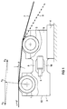
- FIG 1 shows a particularly advantageous embodiment of a device according to the invention for measuring the tensile force F B in a metal strip 7, in particular a steel strip.
- This device has a bearing block 12 with a free end 3 and an end 9 anchored in an anchor 4.
- the free end 3 of the bearing block 12 and the anchored end 9 of the bearing block 12 are connected to one another via bending beams 5 and 10.
- two bending beams 5 and 10 are provided. However, more bending beams can be provided.
- a roller 1 is arranged, over which a metal strip 7 is guided.
- the metal strip 7 runs away from the roll 1 at an entry angle ⁇ with respect to the horizontal and away from the roll 1 at an exit angle ⁇ with respect to the horizontal.
- an entry angle ⁇ 0 ° is assumed.
- deflection roller 2 at the anchored end 9 of the bearing block 1, over which the metal strip 7 is guided.
- the deflection roller 2 is arranged in such a way that a fixed and non-variable discharge angle ⁇ results regardless of a device following the bearing block. It has also proven to be particularly advantageous to arrange the rollers 1 and 2 in such a way that a run-off angle ⁇ of 3 to 15 °, advantageously 5 to 10 °. With such a choice of the run-off angle ⁇ , a particularly precise value for the tensile force F B in the metal strip 7 can be determined.
- the force F R acting on the roller 1 leads due to the elasticity in the bending beams 5 and 10 to a substantially vertical displacement of the free end 3 of this bearing block 12 relative to the anchored end 9 of the bearing block 12.
- This deflection is determined by means of a sensor 6 measured, which is advantageously designed as a capacitive sensor.
- the dashed line 8 shows a possible course of the Metal strip 7, such a change in the course the metal strip 7 by a device behind the bearing block 12 is caused. This applies in particular if the bearing block 12 has a reel for reeling the metal strip 7 follows.
- the design according to FIG 1 is particularly characterized by the measurement of a vertical shift. Measuring one vertical or approximately vertical displacement is for the tape tension measurement is particularly advantageous.
- 2 and 3 illustrate the measuring principle for measuring the tensile force in a metal strip 7 by means of the invention Facility.
- 2 shows the bending beams 5 and 10 between the free end 3 of the bearing block and the anchored End 9 of the bearing block in the unloaded state, i.e. in the Condition by no force on the free end 3 of the bearing block works.
- Reference numeral 6 designates the sensor for measurement the vertical displacement of the free end 3 of the bearing block opposite the anchored end 9 of the bearing block.
- the sensor 6 is designed and has a capacitive sensor on one side at least two electrodes 13 and 14 and on the other side at least one electrode 15.
- FIG. 3 shows the section of the bearing block 12 from FIG. 2 in the loaded state, ie in the state in which a force is exerted on the free end 3 of the bearing block 1 due to the tensile force F B in the metal strip 7. Due to the elasticity of the bending beams 5 and 10, this force causes a displacement of the free end 3 of the bearing block relative to the anchored end 9 of the bearing block. This shift is measured by the sensor 6. The displacement of the free end 3 relative to the anchored end 9 also displaces the electrodes 13 and 14 relative to the electrode 15, which results in a change in capacitance in the arrangement of the electrodes 13, 14 and 15 acting as a capacitor. This change in capacity is measured and converted into a vertical path change or into force.
- the electrodes 13, 14, 15 of the capacitor are advantageously designed as capacitor plates.
- the formation of the sensor 6 of the device according to the invention for measuring the tensile force in a metal strip 7 as a capacitive sensor is particularly advantageous.
- the capacitive sensor is particularly advantageously arranged such that the capacitor plates are perpendicular to the main direction of deformation or approximately perpendicular to the main direction of deformation.
- the main direction of deformation is the direction of the maximum displacement of the free end 3 of the bearing block 12, caused by the tensile force F B in the metal strip 7. If the capacitive sensor is arranged such that the capacitor plates are approximately perpendicular to the main direction of deformation, deformations in the remaining ones be neglected in both directions.
- ⁇ denotes the dielectric constant
- A the area the capacitor plates and a the distance between the capacitor plates from each other.
- FIG. 6 shows an exemplary embodiment of a device according to the invention for measuring the tensile force in a metal strip in an alternative embodiment to the exemplary embodiment according to FIGS. 1, 2 and 3.
- the reference numerals 1, 2, 3, 4, 5, 7, 8, 9, 10 and 12 correspond to the reference numerals 1,2,3,4,5,7,8,9,10 and 12 in FIG 1.
- a sensor 11 for measuring this displacement is arranged below the free end of the bearing block 12 in the exemplary embodiment according to FIG.
- the sensor 11 is advantageously arranged between the free end 3 of the bearing block 12 and a foundation 18 or a support.
- the advantageous embodiment of the device according to the invention 1 and 6 for measuring the tensile force in a metal strip 7 is particularly advantageous for measuring the tensile force in a metal band 7 in front of or behind a reel, used in particular between a reel and a roll stand. If the device according to FIG 1 or FIG 6 between a rolling stand from which a metal strip runs out, and one Reel on which the metal strip is wound, arranged, so it should be used according to FIG. 1 or 6.
- FIG. 7 shows a further alternative exemplary embodiment for a device according to the invention for measuring the tensile force in a metal strip.
- Reference numerals 1, 3, 4, 5, 6, 7, 9, 10 and 12 correspond to the corresponding reference numerals in FIG. 1.
- the drain angle ⁇ arises according to the arrangement between the bearing block 12 and a subsequent device, for. B. a reel or a roll stand.
- FIG. 8 shows a further alternative exemplary embodiment for an inventive device for measuring the tensile force in a metal band.
- Reference numerals 1, 3, 5, 6 correspond to 7, 9, 10 and 12 have the corresponding reference symbols in FIG. 1.
- the bearing block 12 is attached to a vertical anchor 4.
- FIG 9 shows a further alternative exemplary embodiment for an inventive device for measuring the tensile force in a metal strip 7.
- Reference numerals 1,3,4,5 correspond to 6,7,9,10 and 12 the corresponding reference numerals in FIG 1.
- the free End 3 of the bearing block 12 over the anchored end 9 of the bearing block 12 arranged.
- the sensor 6 is arranged in such a way that he has a horizontal displacement of the free end 3 of the Bearing blocks opposite the anchored end 9 of the bearing block 12 measures.
Landscapes
- Physics & Mathematics (AREA)
- General Physics & Mathematics (AREA)
- Engineering & Computer Science (AREA)
- Power Engineering (AREA)
- Mechanical Engineering (AREA)
- Force Measurement Appropriate To Specific Purposes (AREA)
- Vessels, Lead-In Wires, Accessory Apparatuses For Cathode-Ray Tubes (AREA)
- Investigating Strength Of Materials By Application Of Mechanical Stress (AREA)
Abstract
Description
Im einzelnen zeigen:
- FIG 1
- eine Einrichtung zur Messung der Zugkraft in einem Metallband,
- FIG 2
- einen Ausschnitt einer Einrichtung zur Messung der Zugkraft in einem Metallband im unbelasteten Zustand,
- FIG 3
- einen Ausschnitt einer Einrichtung zur Messung der Zugkraft in einem Metallband im belasteten Zustand,
- FIG 4
- ein Kräftediagramm,
- FIG 5
- einen Ausschnitt einer Einrichtung zur Messung der Zugkraft in einem Metallband,
- FIG 6
- eine alternative Ausfuhrung einer Einrichtung zur Messung der Zugkraft in einem Metallband,
- FIG 7
- eine weitere alternative Ausführung einer Einrichtung zur Messung der Zugkraft in einem Metallband,
- FIG 8
- eine weitere alternative Ausführung einer Einrichtung zur Messung der Zugkraft in einem Metallband und
- FIG 9
- eine weitere alternative Ausführung einer Einrichtung zur Messung der Zugkraft in einem Metallband.
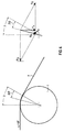
- FB
- die Zugkraft im Metallband 7
- FR
- die resultierende Kraft auf die Rolle 1
- Fv
- die Vertikalkomponente der resultierenden Kraft FR auf die Rolle 1
- Fh
- die Horizontalkomponente der resultierenden Kraft FR auf die Rolle 1.
- der Einlaufwinkel α ist 0°
- der Ablaufwinkel von der Meßrolle β ist 5 bis 10°
- die Reaktionskräfte verteilen sich symmetrisch auf zwei Lager, in denen die Rolle gelagert ist.
| β | FB / FB | Fv / FB | Fh / FB |
| 5° | 1 | 0.04358 | 0.00190 |
| 7.5° | 1 | 0.06526 | 0.00428 |
| 10° | 1 | 0.08682 | 0.00760 |
- wobei E
- der Elastizitätsmodul = 206000 N/mm2,
b die Breite der Biegeträger
h die Dicke der Biegeträger
l die Länge der Biegeträger
Unter der Voraussetzung geringer Verformungen erfolgt eine zusätzliche Streckung ΔlB bzw. Stauchung ΔlA der Biegeträger 5 bzw. 10, die zu einem Abkippen des freien Endes 3 des Lagerblocks 12 gegenüber dem verankerten Ende 9 des Lagerblocks 12 führt.
Claims (14)
- Einrichtung zur Messung der Zugkraft (FB) in einem Metallband (7) einer Walzstraße, wobei das Metallband (7) über eine Rolle (1) geführt wird, die in einem Lagerblock (12) gelagert ist,
dadurch gekennzeichnet,
daß der Lagerblock (12) ein verankertes Ende (9) und ein freies Ende (3) aufweist, wobei die Rolle (1) im Bereich des freien Endes (3) des Lagerblocks (12) angeordnet ist und wobei die Einrichtung zur Messung der Zugkraft (FB) einen, insbesondere als kapazitiven Sensor bzw. als Plattenkondensator ausgebildeten, Sensor (6,11) zur Messung einer Lageänderung des freien Endes (3) des Lagerblocks (12) gegenüber dem verankerten Ende (9) des Lagerblocks (12) aufweist. - Einrichtung nach Anspruch 1,
dadurch gekennzeichnet,
daß sie zumindest zwei Biegeträger (5,10) zwischen dem freien Ende (3) und dem verankerten Ende (9) des Lagerblocks (12) aufweist. - Einrichtung nach Anspruch 1 oder 2,
dadurch gekennzeichnet,
daß der Sensor (6,11) eine Lageänderung (f) des freien Endes (3) des Lagerblocks (12) gegenüber dem verankerten Ende (9) des Lagerblocks (12) in vertikaler Richtung messend ausgebildet ist. - Einrichtung nach Anspruch 1, 2 oder 3,
dadurch gekennzeichnet,
daß der Sensor (6) zwischen dem freien Ende (3) des Lagerblocks (12) und dem verankerten Ende (9) des Lagerblocks (12) angeordnet ist. - Einrichtung nach Anspruch 1, 2, 3 oder 4,
dadurch gekennzeichnet,
daß der Sensor (11) unterhalb des freien Endes (3) des Lagerblocks (12) angeordnet ist. - Einrichtung nach Anspruch 1, 2, 3, 4 oder 5,
dadurch gekennzeichnet,
daß die Kondensatorplatten (13,14,15) des als kapazitiven Sensor bzw. als Plattenkondensator ausgebildeten Sensors (6,11) parallel bzw. weitestgehend parallel zu den Biegeträgern (5,10) angeordnet sind. - Einrichtung nach einem der Ansprüche 1 bis 6,
dadurch gekennzeichnet,
daß der Lagerblock (12) eine Umlenkrolle (2) über die das Metallband (7) geführt wird, aufweist. - Einrichtung nach Anspruch 7,
dadurch gekennzeichnet,
daß die Umlenkrolle (2) im Bereich des verankerten Endes (9) des Lagerblocks (12) angeordnet ist. - Einrichtung nach Anspruch 7 oder 8,
dadurch gekennzeichnet,
daß die Umlenkrolle (2) in Laufrichtung des Metallbandes (7) hinter der Rolle (1) angeordnet ist. - Einrichtung nach Anspruch 7, 8 oder 9,
dadurch gekennzeichnet,
daß die Rolle (1) und die Umlenkrolle (2) derart angeordnet sind, daß das Metallband (7) zwischen ihnen einen Winkel β gegenüber der Horizontalen von 3° bis 15° aufweist. - Einrichtung nach einem der Ansprüche 1 bis 10,
dadurch gekennzeichnet,
daß sie zwischen dem letzten Walzgerüst der Walzstraße und einem Haspel zum Aufhaspeln des Metallbandes angeordnet ist. - Einrichtung nach einem der Ansprüche 1 bis 11,
dadurch gekennzeichnet,
daß sie zwischen einem Haspel zum Abhaspeln des Metallbandes und dem ersten Walzgerüst der Walzstraße angeordnet ist. - Einrichtung nach einem der vorhergehenden Ansprüche,
dadurch gekennzeichnet,
daß das Metallband ein Stahlband ist. - Einrichtung nach einem der vorhergehenden Ansprüche ,
dadurch gekennzeichnet,
daß die Walzstraße eine Kaltwalzstraße ist.
Applications Claiming Priority (2)
| Application Number | Priority Date | Filing Date | Title |
|---|---|---|---|
| DE19744032A DE19744032A1 (de) | 1997-10-06 | 1997-10-06 | Einrichtung zur Messung der Zugkraft in einem Metallband |
| DE19744032 | 1997-10-06 |
Publications (3)
| Publication Number | Publication Date |
|---|---|
| EP0908247A2 true EP0908247A2 (de) | 1999-04-14 |
| EP0908247A3 EP0908247A3 (de) | 2002-09-18 |
| EP0908247B1 EP0908247B1 (de) | 2004-11-17 |
Family
ID=7844691
Family Applications (1)
| Application Number | Title | Priority Date | Filing Date |
|---|---|---|---|
| EP98117997A Expired - Lifetime EP0908247B1 (de) | 1997-10-06 | 1998-09-23 | Einrichtung zur Messung der Zugkraft in einem Metallband |
Country Status (3)
| Country | Link |
|---|---|
| EP (1) | EP0908247B1 (de) |
| AT (1) | ATE282487T1 (de) |
| DE (2) | DE19744032A1 (de) |
Cited By (1)
| Publication number | Priority date | Publication date | Assignee | Title |
|---|---|---|---|---|
| DE102007035037A1 (de) * | 2007-07-26 | 2009-01-29 | Continental Automotive Gmbh | Messvorrichtung zur Bestimmung von Gurtkräften |
Families Citing this family (3)
| Publication number | Priority date | Publication date | Assignee | Title |
|---|---|---|---|---|
| DE102006023529B4 (de) * | 2006-05-19 | 2008-07-03 | Tensometric-Meßtechnik GmbH | Anordnung zur Zugkraftmessung von Endlosmaterial |
| DE102006057258B4 (de) * | 2006-11-22 | 2010-04-08 | Brosa Ag | Torsionsunanfälliger Kraftaufnehmer mit Steg in Zentralöffnung |
| JP2008267923A (ja) * | 2007-04-18 | 2008-11-06 | Nitta Ind Corp | 張力測定装置 |
Family Cites Families (5)
| Publication number | Priority date | Publication date | Assignee | Title |
|---|---|---|---|---|
| DE739436C (de) * | 1940-04-09 | 1943-09-25 | Aeg | Einrichtung zum Messen der Spannung von bandfoermigem Walzgut |
| GB643775A (en) * | 1948-03-05 | 1950-09-27 | English Electric Co Ltd | Apparatus for providing a continuous indication dependent on the tension in material passing through a treating machine |
| US2809519A (en) * | 1954-09-22 | 1957-10-15 | Olin Mathieson | Web flatness indicator |
| FR2453396A1 (fr) * | 1979-04-02 | 1980-10-31 | Testut Aequitas | Recepteur de charge a parallelogramme d'une seule piece et transducteur capacitif |
| JPH0786440B2 (ja) * | 1990-03-16 | 1995-09-20 | 日本フィリップス株式会社 | 張力測定装置 |
-
1997
- 1997-10-06 DE DE19744032A patent/DE19744032A1/de not_active Ceased
-
1998
- 1998-09-23 EP EP98117997A patent/EP0908247B1/de not_active Expired - Lifetime
- 1998-09-23 AT AT98117997T patent/ATE282487T1/de not_active IP Right Cessation
- 1998-09-23 DE DE59812268T patent/DE59812268D1/de not_active Expired - Fee Related
Cited By (1)
| Publication number | Priority date | Publication date | Assignee | Title |
|---|---|---|---|---|
| DE102007035037A1 (de) * | 2007-07-26 | 2009-01-29 | Continental Automotive Gmbh | Messvorrichtung zur Bestimmung von Gurtkräften |
Also Published As
| Publication number | Publication date |
|---|---|
| DE59812268D1 (de) | 2004-12-23 |
| ATE282487T1 (de) | 2004-12-15 |
| EP0908247A3 (de) | 2002-09-18 |
| DE19744032A1 (de) | 1999-04-08 |
| EP0908247B1 (de) | 2004-11-17 |
Similar Documents
| Publication | Publication Date | Title |
|---|---|---|
| DE2334492C2 (de) | Vorrichtung zur kontinuierlichen Steuerung der Ebenheit und Parallelität von Walzgutoberflächen | |
| DE60122069T2 (de) | Walzwerk mit Bandprofilerfassungseinrichtung und Bandprofilerfassungsverfahren | |
| EP0949493A1 (de) | Kraftaufnehmer des doppelbalkentyps | |
| DE3721746C2 (de) | ||
| DE1573698A1 (de) | Verfahren zum Messen der Verteilung von Zugspannungen ueber die Breite von unter Laengszug stehendem bandfoermigem Gut und zugehoerige Messvorrichtung | |
| DE2612744C2 (de) | Gleitlager für Walzgerüstwalzen | |
| EP0908247B1 (de) | Einrichtung zur Messung der Zugkraft in einem Metallband | |
| DE2124112A1 (de) | Hohlzylindrischer Meßgrößenumformer mit Beanspru chungsmeßeinrichtungen | |
| DE3841106A1 (de) | Kompensator fuer eine pendelwalze | |
| DE2459248C2 (de) | Regelungs-Vorrichtung zum Ausregeln walzkraftbedingter Walzendurchbiegungen | |
| DE2544556A1 (de) | Stuetzrollengeruest fuer stahl-brammenstranggiessanlagen, insbesondere fuer bogen- brammenstranggiessanlagen | |
| EP0698428B1 (de) | Einrichtung zur Erfassung des Walzspaltes zwischen zwei Arbeitswalzen eines Walzgerüstes | |
| DE2030409C3 (de) | Verfahren und Vorrichtung zur Messung der Form von Stahlbandern unter Zugspannung | |
| DE1752959C3 (de) | Vorrichtung zum Vermeiden von Planheitsabweichungen an kaltgewalztem Metallband während des Walzens unter Längszug | |
| WO2008055886A1 (de) | Regelverfahren für ein walzgerüst, walzanordnung und walzstrasse | |
| AT390741B (de) | Walzwerk, insbesondere kaltwalzwerk | |
| EP0175844A2 (de) | Verfahren und Vorrichtung zur Korrektur des Dickenprofils des zu walzenden Bandes an einer mehrgerüstigen Warmbandstrasse | |
| DE1752052C3 (de) | Walzgerüst zum Dressieren von kaltgewalztem Metallband | |
| DE102006023529B4 (de) | Anordnung zur Zugkraftmessung von Endlosmaterial | |
| DE1427796A1 (de) | Anordnung zum Messen des Walzdruckes in Walzenstuehlen | |
| EP0891435A1 (de) | Vorrichtung zum messen der dicke und/oder der ungleichmässigkeit von watten oder vliesen | |
| DE1752968B2 (de) | Vorgespanntes Walzgerüst mit Walzen-Rückbiegeeinrichtungen | |
| DE2363841A1 (de) | Strangfuehrungsgeruest zum stuetzen eines teilweise erstarrten stranges in einer stranggiessanlage | |
| DE1527739A1 (de) | Walzenbiegevorrichtung | |
| DE1158025B (de) | Regeleinrichtung fuer Walzgerueste |
Legal Events
| Date | Code | Title | Description |
|---|---|---|---|
| PUAI | Public reference made under article 153(3) epc to a published international application that has entered the european phase |
Free format text: ORIGINAL CODE: 0009012 |
|
| AK | Designated contracting states |
Kind code of ref document: A2 Designated state(s): AT BE CH CY DE DK ES FI FR GB GR IE IT LI LU MC NL PT SE |
|
| AX | Request for extension of the european patent |
Free format text: AL;LT;LV;MK;RO;SI |
|
| PUAL | Search report despatched |
Free format text: ORIGINAL CODE: 0009013 |
|
| AK | Designated contracting states |
Kind code of ref document: A3 Designated state(s): AT BE CH CY DE DK ES FI FR GB GR IE IT LI LU MC NL PT SE |
|
| AX | Request for extension of the european patent |
Free format text: AL;LT;LV;MK;RO;SI |
|
| RIC1 | Information provided on ipc code assigned before grant |
Free format text: 7B 21B 38/06 A, 7G 01L 5/10 B, 7G 01L 1/14 B |
|
| 17P | Request for examination filed |
Effective date: 20030303 |
|
| AKX | Designation fees paid |
Designated state(s): AT DE FI SE |
|
| 17Q | First examination report despatched |
Effective date: 20030917 |
|
| GRAP | Despatch of communication of intention to grant a patent |
Free format text: ORIGINAL CODE: EPIDOSNIGR1 |
|
| GRAS | Grant fee paid |
Free format text: ORIGINAL CODE: EPIDOSNIGR3 |
|
| GRAA | (expected) grant |
Free format text: ORIGINAL CODE: 0009210 |
|
| AK | Designated contracting states |
Kind code of ref document: B1 Designated state(s): AT DE FI SE |
|
| REG | Reference to a national code |
Ref country code: IE Ref legal event code: FG4D Free format text: GERMAN |
|
| REF | Corresponds to: |
Ref document number: 59812268 Country of ref document: DE Date of ref document: 20041223 Kind code of ref document: P |
|
| REG | Reference to a national code |
Ref country code: SE Ref legal event code: TRGR |
|
| REG | Reference to a national code |
Ref country code: IE Ref legal event code: FD4D |
|
| PLBE | No opposition filed within time limit |
Free format text: ORIGINAL CODE: 0009261 |
|
| STAA | Information on the status of an ep patent application or granted ep patent |
Free format text: STATUS: NO OPPOSITION FILED WITHIN TIME LIMIT |
|
| 26N | No opposition filed |
Effective date: 20050818 |
|
| PGFP | Annual fee paid to national office [announced via postgrant information from national office to epo] |
Ref country code: DE Payment date: 20081121 Year of fee payment: 11 |
|
| PGFP | Annual fee paid to national office [announced via postgrant information from national office to epo] |
Ref country code: SE Payment date: 20090908 Year of fee payment: 12 Ref country code: FI Payment date: 20090908 Year of fee payment: 12 Ref country code: AT Payment date: 20090813 Year of fee payment: 12 |
|
| PG25 | Lapsed in a contracting state [announced via postgrant information from national office to epo] |
Ref country code: DE Free format text: LAPSE BECAUSE OF NON-PAYMENT OF DUE FEES Effective date: 20100401 |
|
| REG | Reference to a national code |
Ref country code: SE Ref legal event code: EUG |
|
| PG25 | Lapsed in a contracting state [announced via postgrant information from national office to epo] |
Ref country code: FI Free format text: LAPSE BECAUSE OF NON-PAYMENT OF DUE FEES Effective date: 20100923 |
|
| PG25 | Lapsed in a contracting state [announced via postgrant information from national office to epo] |
Ref country code: AT Free format text: LAPSE BECAUSE OF NON-PAYMENT OF DUE FEES Effective date: 20100923 |
|
| PG25 | Lapsed in a contracting state [announced via postgrant information from national office to epo] |
Ref country code: SE Free format text: LAPSE BECAUSE OF NON-PAYMENT OF DUE FEES Effective date: 20100924 |