EP0908259A2 - Plaquette de coupe, son procédé de fabrication ainsi qu'un outil et une méthode d'usinage utilisant cette plaquette - Google Patents
Plaquette de coupe, son procédé de fabrication ainsi qu'un outil et une méthode d'usinage utilisant cette plaquette Download PDFInfo
- Publication number
- EP0908259A2 EP0908259A2 EP98115382A EP98115382A EP0908259A2 EP 0908259 A2 EP0908259 A2 EP 0908259A2 EP 98115382 A EP98115382 A EP 98115382A EP 98115382 A EP98115382 A EP 98115382A EP 0908259 A2 EP0908259 A2 EP 0908259A2
- Authority
- EP
- European Patent Office
- Prior art keywords
- cutting
- coating
- tool
- cutting insert
- free
- Prior art date
- Legal status (The legal status is an assumption and is not a legal conclusion. Google has not performed a legal analysis and makes no representation as to the accuracy of the status listed.)
- Withdrawn
Links
- 238000005520 cutting process Methods 0.000 title claims abstract description 165
- 238000003754 machining Methods 0.000 title claims abstract description 28
- 238000000034 method Methods 0.000 title claims description 41
- 238000004519 manufacturing process Methods 0.000 title claims description 4
- 238000000576 coating method Methods 0.000 claims description 51
- 239000011248 coating agent Substances 0.000 claims description 39
- 239000000463 material Substances 0.000 claims description 30
- 239000011230 binding agent Substances 0.000 claims description 11
- 238000003801 milling Methods 0.000 claims description 10
- 238000007514 turning Methods 0.000 claims description 8
- 229910018072 Al 2 O 3 Inorganic materials 0.000 claims description 7
- 238000000227 grinding Methods 0.000 claims description 7
- 239000000203 mixture Substances 0.000 claims description 7
- 239000010432 diamond Substances 0.000 claims description 5
- 229910003460 diamond Inorganic materials 0.000 claims description 5
- 238000005245 sintering Methods 0.000 claims description 5
- PXHVJJICTQNCMI-UHFFFAOYSA-N Nickel Chemical compound [Ni] PXHVJJICTQNCMI-UHFFFAOYSA-N 0.000 claims description 4
- ATJFFYVFTNAWJD-UHFFFAOYSA-N Tin Chemical compound [Sn] ATJFFYVFTNAWJD-UHFFFAOYSA-N 0.000 claims description 4
- 239000010431 corundum Substances 0.000 claims description 4
- 229910052593 corundum Inorganic materials 0.000 claims description 4
- 239000013078 crystal Substances 0.000 claims description 4
- 238000000151 deposition Methods 0.000 claims description 4
- 230000008021 deposition Effects 0.000 claims description 4
- 229910052581 Si3N4 Inorganic materials 0.000 claims description 3
- 238000009499 grossing Methods 0.000 claims description 3
- 230000035939 shock Effects 0.000 claims description 3
- HQVNEWCFYHHQES-UHFFFAOYSA-N silicon nitride Chemical compound N12[Si]34N5[Si]62N3[Si]51N64 HQVNEWCFYHHQES-UHFFFAOYSA-N 0.000 claims description 3
- 238000005299 abrasion Methods 0.000 claims description 2
- 238000009713 electroplating Methods 0.000 claims description 2
- 229910052759 nickel Inorganic materials 0.000 claims description 2
- 239000002245 particle Substances 0.000 claims description 2
- 229910052594 sapphire Inorganic materials 0.000 claims description 2
- 239000010980 sapphire Substances 0.000 claims description 2
- 238000005476 soldering Methods 0.000 claims description 2
- 238000005507 spraying Methods 0.000 claims description 2
- 239000010410 layer Substances 0.000 description 16
- 230000008569 process Effects 0.000 description 14
- 238000005229 chemical vapour deposition Methods 0.000 description 5
- 230000015572 biosynthetic process Effects 0.000 description 3
- 239000000919 ceramic Substances 0.000 description 3
- 230000000694 effects Effects 0.000 description 3
- 230000003466 anti-cipated effect Effects 0.000 description 2
- 230000008859 change Effects 0.000 description 2
- 239000011159 matrix material Substances 0.000 description 2
- 230000007246 mechanism Effects 0.000 description 2
- 230000006641 stabilisation Effects 0.000 description 2
- 238000011105 stabilization Methods 0.000 description 2
- 230000007704 transition Effects 0.000 description 2
- 229910052580 B4C Inorganic materials 0.000 description 1
- 229910000831 Steel Inorganic materials 0.000 description 1
- 230000009471 action Effects 0.000 description 1
- 230000005540 biological transmission Effects 0.000 description 1
- INAHAJYZKVIDIZ-UHFFFAOYSA-N boron carbide Chemical compound B12B3B4C32B41 INAHAJYZKVIDIZ-UHFFFAOYSA-N 0.000 description 1
- 229910010293 ceramic material Inorganic materials 0.000 description 1
- 230000003749 cleanliness Effects 0.000 description 1
- 238000012937 correction Methods 0.000 description 1
- 238000013016 damping Methods 0.000 description 1
- 238000005553 drilling Methods 0.000 description 1
- 230000005489 elastic deformation Effects 0.000 description 1
- 238000005516 engineering process Methods 0.000 description 1
- 238000001704 evaporation Methods 0.000 description 1
- 238000010438 heat treatment Methods 0.000 description 1
- 230000010354 integration Effects 0.000 description 1
- 239000002184 metal Substances 0.000 description 1
- 229910052751 metal Inorganic materials 0.000 description 1
- 150000001247 metal acetylides Chemical class 0.000 description 1
- 239000007769 metal material Substances 0.000 description 1
- 238000003825 pressing Methods 0.000 description 1
- 238000004904 shortening Methods 0.000 description 1
- 229910010271 silicon carbide Inorganic materials 0.000 description 1
- HBMJWWWQQXIZIP-UHFFFAOYSA-N silicon carbide Chemical compound [Si+]#[C-] HBMJWWWQQXIZIP-UHFFFAOYSA-N 0.000 description 1
- 239000010959 steel Substances 0.000 description 1
- 239000002344 surface layer Substances 0.000 description 1
- UONOETXJSWQNOL-UHFFFAOYSA-N tungsten carbide Chemical compound [W+]#[C-] UONOETXJSWQNOL-UHFFFAOYSA-N 0.000 description 1
- 238000001771 vacuum deposition Methods 0.000 description 1
Images

Classifications
-
- C—CHEMISTRY; METALLURGY
- C23—COATING METALLIC MATERIAL; COATING MATERIAL WITH METALLIC MATERIAL; CHEMICAL SURFACE TREATMENT; DIFFUSION TREATMENT OF METALLIC MATERIAL; COATING BY VACUUM EVAPORATION, BY SPUTTERING, BY ION IMPLANTATION OR BY CHEMICAL VAPOUR DEPOSITION, IN GENERAL; INHIBITING CORROSION OF METALLIC MATERIAL OR INCRUSTATION IN GENERAL
- C23C—COATING METALLIC MATERIAL; COATING MATERIAL WITH METALLIC MATERIAL; SURFACE TREATMENT OF METALLIC MATERIAL BY DIFFUSION INTO THE SURFACE, BY CHEMICAL CONVERSION OR SUBSTITUTION; COATING BY VACUUM EVAPORATION, BY SPUTTERING, BY ION IMPLANTATION OR BY CHEMICAL VAPOUR DEPOSITION, IN GENERAL
- C23C28/00—Coating for obtaining at least two superposed coatings either by methods not provided for in a single one of groups C23C2/00 - C23C26/00 or by combinations of methods provided for in subclasses C23C and C25C or C25D
- C23C28/04—Coating for obtaining at least two superposed coatings either by methods not provided for in a single one of groups C23C2/00 - C23C26/00 or by combinations of methods provided for in subclasses C23C and C25C or C25D only coatings of inorganic non-metallic material
- C23C28/044—Coating for obtaining at least two superposed coatings either by methods not provided for in a single one of groups C23C2/00 - C23C26/00 or by combinations of methods provided for in subclasses C23C and C25C or C25D only coatings of inorganic non-metallic material coatings specially adapted for cutting tools or wear applications
-
- B—PERFORMING OPERATIONS; TRANSPORTING
- B23—MACHINE TOOLS; METAL-WORKING NOT OTHERWISE PROVIDED FOR
- B23B—TURNING; BORING
- B23B27/00—Tools for turning or boring machines; Tools of a similar kind in general; Accessories therefor
- B23B27/14—Cutting tools of which the bits or tips or cutting inserts are of special material
- B23B27/141—Specially shaped plate-like cutting inserts, i.e. length greater or equal to width, width greater than or equal to thickness
- B23B27/145—Specially shaped plate-like cutting inserts, i.e. length greater or equal to width, width greater than or equal to thickness characterised by having a special shape
-
- C—CHEMISTRY; METALLURGY
- C23—COATING METALLIC MATERIAL; COATING MATERIAL WITH METALLIC MATERIAL; CHEMICAL SURFACE TREATMENT; DIFFUSION TREATMENT OF METALLIC MATERIAL; COATING BY VACUUM EVAPORATION, BY SPUTTERING, BY ION IMPLANTATION OR BY CHEMICAL VAPOUR DEPOSITION, IN GENERAL; INHIBITING CORROSION OF METALLIC MATERIAL OR INCRUSTATION IN GENERAL
- C23C—COATING METALLIC MATERIAL; COATING MATERIAL WITH METALLIC MATERIAL; SURFACE TREATMENT OF METALLIC MATERIAL BY DIFFUSION INTO THE SURFACE, BY CHEMICAL CONVERSION OR SUBSTITUTION; COATING BY VACUUM EVAPORATION, BY SPUTTERING, BY ION IMPLANTATION OR BY CHEMICAL VAPOUR DEPOSITION, IN GENERAL
- C23C30/00—Coating with metallic material characterised only by the composition of the metallic material, i.e. not characterised by the coating process
- C23C30/005—Coating with metallic material characterised only by the composition of the metallic material, i.e. not characterised by the coating process on hard metal substrates
-
- B—PERFORMING OPERATIONS; TRANSPORTING
- B23—MACHINE TOOLS; METAL-WORKING NOT OTHERWISE PROVIDED FOR
- B23B—TURNING; BORING
- B23B2200/00—Details of cutting inserts
- B23B2200/28—Angles
-
- B—PERFORMING OPERATIONS; TRANSPORTING
- B23—MACHINE TOOLS; METAL-WORKING NOT OTHERWISE PROVIDED FOR
- B23B—TURNING; BORING
- B23B2226/00—Materials of tools or workpieces not comprising a metal
- B23B2226/12—Boron nitride
- B23B2226/125—Boron nitride cubic [CBN]
-
- B—PERFORMING OPERATIONS; TRANSPORTING
- B23—MACHINE TOOLS; METAL-WORKING NOT OTHERWISE PROVIDED FOR
- B23B—TURNING; BORING
- B23B2228/00—Properties of materials of tools or workpieces, materials of tools or workpieces applied in a specific manner
- B23B2228/04—Properties of materials of tools or workpieces, materials of tools or workpieces applied in a specific manner applied by chemical vapour deposition [CVD]
-
- B—PERFORMING OPERATIONS; TRANSPORTING
- B23—MACHINE TOOLS; METAL-WORKING NOT OTHERWISE PROVIDED FOR
- B23B—TURNING; BORING
- B23B2228/00—Properties of materials of tools or workpieces, materials of tools or workpieces applied in a specific manner
- B23B2228/08—Properties of materials of tools or workpieces, materials of tools or workpieces applied in a specific manner applied by physical vapour deposition [PVD]
-
- B—PERFORMING OPERATIONS; TRANSPORTING
- B23—MACHINE TOOLS; METAL-WORKING NOT OTHERWISE PROVIDED FOR
- B23B—TURNING; BORING
- B23B2228/00—Properties of materials of tools or workpieces, materials of tools or workpieces applied in a specific manner
- B23B2228/10—Coatings
-
- B—PERFORMING OPERATIONS; TRANSPORTING
- B23—MACHINE TOOLS; METAL-WORKING NOT OTHERWISE PROVIDED FOR
- B23B—TURNING; BORING
- B23B2270/00—Details of turning, boring or drilling machines, processes or tools not otherwise provided for
- B23B2270/26—Burnishing
-
- Y—GENERAL TAGGING OF NEW TECHNOLOGICAL DEVELOPMENTS; GENERAL TAGGING OF CROSS-SECTIONAL TECHNOLOGIES SPANNING OVER SEVERAL SECTIONS OF THE IPC; TECHNICAL SUBJECTS COVERED BY FORMER USPC CROSS-REFERENCE ART COLLECTIONS [XRACs] AND DIGESTS
- Y10—TECHNICAL SUBJECTS COVERED BY FORMER USPC
- Y10T—TECHNICAL SUBJECTS COVERED BY FORMER US CLASSIFICATION
- Y10T407/00—Cutters, for shaping
- Y10T407/10—Cutters, for shaping including noncutting work modifying means
-
- Y—GENERAL TAGGING OF NEW TECHNOLOGICAL DEVELOPMENTS; GENERAL TAGGING OF CROSS-SECTIONAL TECHNOLOGIES SPANNING OVER SEVERAL SECTIONS OF THE IPC; TECHNICAL SUBJECTS COVERED BY FORMER USPC CROSS-REFERENCE ART COLLECTIONS [XRACs] AND DIGESTS
- Y10—TECHNICAL SUBJECTS COVERED BY FORMER USPC
- Y10T—TECHNICAL SUBJECTS COVERED BY FORMER US CLASSIFICATION
- Y10T407/00—Cutters, for shaping
- Y10T407/26—Cutters, for shaping comprising cutting edge bonded to tool shank
-
- Y—GENERAL TAGGING OF NEW TECHNOLOGICAL DEVELOPMENTS; GENERAL TAGGING OF CROSS-SECTIONAL TECHNOLOGIES SPANNING OVER SEVERAL SECTIONS OF THE IPC; TECHNICAL SUBJECTS COVERED BY FORMER USPC CROSS-REFERENCE ART COLLECTIONS [XRACs] AND DIGESTS
- Y10—TECHNICAL SUBJECTS COVERED BY FORMER USPC
- Y10T—TECHNICAL SUBJECTS COVERED BY FORMER US CLASSIFICATION
- Y10T407/00—Cutters, for shaping
- Y10T407/27—Cutters, for shaping comprising tool of specific chemical composition
-
- Y—GENERAL TAGGING OF NEW TECHNOLOGICAL DEVELOPMENTS; GENERAL TAGGING OF CROSS-SECTIONAL TECHNOLOGIES SPANNING OVER SEVERAL SECTIONS OF THE IPC; TECHNICAL SUBJECTS COVERED BY FORMER USPC CROSS-REFERENCE ART COLLECTIONS [XRACs] AND DIGESTS
- Y10—TECHNICAL SUBJECTS COVERED BY FORMER USPC
- Y10T—TECHNICAL SUBJECTS COVERED BY FORMER US CLASSIFICATION
- Y10T82/00—Turning
- Y10T82/10—Process of turning
-
- Y—GENERAL TAGGING OF NEW TECHNOLOGICAL DEVELOPMENTS; GENERAL TAGGING OF CROSS-SECTIONAL TECHNOLOGIES SPANNING OVER SEVERAL SECTIONS OF THE IPC; TECHNICAL SUBJECTS COVERED BY FORMER USPC CROSS-REFERENCE ART COLLECTIONS [XRACs] AND DIGESTS
- Y10—TECHNICAL SUBJECTS COVERED BY FORMER USPC
- Y10T—TECHNICAL SUBJECTS COVERED BY FORMER US CLASSIFICATION
- Y10T82/00—Turning
- Y10T82/30—Miscellaneous
Definitions
- the invention relates to a cutting insert, in particular an indexable insert, according to the preamble of claim 1, a method for Production of such a cutting plate according to the preamble of Claim 18, equipped with such a cutting plate Tool according to the preamble of claim 29 and a method for machining a workpiece using a such insert or tool after Preamble of claim 31.
- the movements during the cutting process are relative movements between a cutting edge and the workpiece.
- the movements are generated by a machine tool and can be circular or any.
- the chips arise when the Cutting wedge formed from free face and rake face after a feed movement penetrates into the workpiece through the active movement.
- They are cutting wedges made of metallic and non-metallic materials known, for example cutting steel, hard metal, ceramic, Mixed ceramics, corundum, silicon carbide, boron carbide, diamond and the like.
- Tungsten carbide inserts in particular can be provided with a very thin surface layer made of extremely fine-grained carbides or ceramics and thus experience a significant increase in wear resistance.
- the most important coating materials which are usually applied by vacuum deposition, are TiCN, TiN, Al 2 O 3 , and TiC.
- the PVD, CVD and arc PVD processes are known for evaporating the coating materials. With the PVD method, maximum layer thicknesses of approximately 2 to 5 ⁇ m can be achieved, with the CVD method, maximum layer thicknesses of approximately 12 to 15 ⁇ m and with the arc PVD method, maximum layer thicknesses up to approximately 50 ⁇ m can be achieved.
- the cutting material or its coating is in surface contact with the workpiece along the rake face.
- the cutting edge is subjected to a wear load due to the cutting movement, which leads to flattening, the so-called chip and flank wear.
- the stress on the surfaces of the cutting wedge by pressure and shear forces under the influence of temperature is different. Accordingly, a distinction is made between different types of failure of the various surface elements, for example open space wear, crater wear, plastic deformation, notch wear, comb crack formation, fatigue fracture, crumbling, tool breakage, built-up edge formation. These types of wear can occur in parallel and impair the cutting process and the surface result on the workpiece. In practice, abrasive wear is permitted for reasons of economy.
- the end of the service life of the cutting edge is determined as a parameter of passive force, the resulting heat and surface quality.
- the wear caused by cutting elements breaking out is generally defined as the end of the service life.
- the cutting wedges are only available as small indexable inserts executed to the tool body over many To be able to use downtimes and to minimize the use of expensive cutting materials. Be at the same time the requirements for today's machining processes the accuracy of the cutting edges is always greater ( ⁇ 0.01 mm). At the Due to the shrinkage, the sintering process is a repeatability over several batches with only additional ones Grinding operations attainable. There must also be high demands to the quality of the recordings for the cutting inserts precise positioning over many insert lifetimes and hold the exchangeable inserts have to. The plates must be replaced and fastened qualified staff to be carried out because of the cleanliness of the Fits and the repeatability of the fastening movement the positional accuracy of the insert.
- the required clearance angle increases with narrowing pitch of the inserts. This is advantageous to achieve shorter tool change times. Furthermore is the size of the clearance angle by the cutting edge radius certainly. A reasonable relationship between Cutting edge radius and chip thickness can be found. Since the Possible effective feed in the unit of time when milling, drilling and broach the sum of feed / tooth and number of teeth / tool narrow division is sought for economic reasons.
- the invention has for its object the generic Cutting insert, the generic method, the generic To design tools and the generic machining process in such a way that in a simple manner and with long tool downtimes or its insert a high machining accuracy is achieved on the workpiece.
- the clearance angle lies on Cutting wedge in the range between 0 ° and approximately 3 °. Because of this low Flank angle, which can even be 0 °, is simple achieved a satisfactory machining result. Is the Flank angle 0 °, a cutting surface is formed, which is connected to the Cutting edge connects. With sufficient stabilization of the The cutting edge becomes the part that presses into the workpiece surface the insert is reduced to a minimum.
- the insert can be made more cost-effectively Easy way.
- the cutting surface is the rake face or the free face in the form of a Coating applied, which is possible in a simple manner.
- the cutting materials contained in the respective coatings corresponding to those that occur during machining with the insert Loads are selected.
- the cutting edges lie in the rotating tool according to the invention the inserts on the circumference of the tool on one imaginary cylinder jacket or any rotationally symmetrical Contour.
- the insert When working with the tool according to the invention or the tool according to the invention
- the insert is placed directly in the open area Following the detachment of the chip from the workpiece, the exposed one Fractured surface smoothed on the workpiece. In this way, in one can be roughed and finished in a single operation.
- the smoothing effect occurs when the chip is removed Roughness peaks in the fractured surface of the workpiece eliminated, see above that subsequent finishing of the workpiece is not necessary is.
- the tool has at least one Insert 1, which in a known manner on a tool holder is attached.
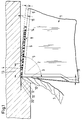
- the insert 1 has a cutting wedge 2, which with a Rake face 3 and a free surface 4 is provided.
- the wedge angle 5 (Fig. 1) is in the range between about 70 ° and 95 ° and is preferably 90 °.
- the clearance angle on the cutting wedge 2 is in the range between 0 ° and about 3 °, preferably at 0 °.
- a workpiece 6 is machined with the indexable insert 1. Here, a chip 7 is lifted from the workpiece 6.
- the free area 4 is covered by at least one coating 8 Insert 1 formed.
- the coating 8 has a thickness 9 of more than at least about 0.02 mm. Instead of this one layer can also be provided several thin layers, which the Form layer 8.
- the rake face 3 has a coating 10 or has a larger one Mass fraction on as the coating 8 of the open area 4.
- the Coating 10 consists of shock-resistant material with a wear-reducing surface, with low roughness, insulating Properties and a low coefficient of friction. This will ensures that the rake face 3 has little wear subject to.
- the free space wear, the surface quality and dimensional accuracy of the workpiece 6 determined can be reduced, reducing the quality and / or quantity of the workpieces that can be produced with the cutting insert 1 6 can be increased. Due to a higher temperature resistance the cutting edge can change the speed of action between the tool and the workpiece 6 can be increased, whereby a Productivity gain is achieved.
- the rake angle 11 (FIG. 1) of the insert 1 is in the range of about -10 ° to about + 15 °.
- the free surface 4 has one on the cutting edge 12 adjoining area 13 which with the rake face 3 Includes clearance angle between about 0 ° and 3 °.
- the area 13 goes then into an open area 14, which has a larger clearance angle 15, which is in the range between about 5 ° and 10 °.
- a very thick wear-resistant layer 8 is applied to the open area 4 and is machined by simple circumferential dressing, similar to the dressing of a grinding wheel, whereby a highly precise tool is produced. After the application of the coating 8, before the first use of the insert 1 or the tool on the free surface 4, wear of the insert is deliberately anticipated.
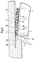
- the coating 8 has a binder 16, in which wear-resistant elements 17 are embedded. They consist of individual CBN monocrystals or similar hard material particles such as Al 2 O 3 (corundum), silicon nitride, sapphire, natural or artificial diamond crystals and the like.
- the monocrystalline cutting elements 17 have a diameter or a cross-sectional width which is of the order of about 0.05 mm.
- the binder 16 enables the CBN monocrystals 17 to be adequately fastened over the service life of the insert 1. If 6 load impacts occur during the machining of the workpiece, the cutting elements 17 or their cutting edges can yield elastically.
- the CBN elements 17 are only provided on those active surfaces of the cutting wedge 2 which experience minor load impacts.
- the CBN elements 17 must show great wear resistance and high warm hardness. At the transition between the impact-loaded rake face 3 and the free face 4 there is a large number of such CBN elements 17, so that after wear of one element 17 the subsequent element is immediately available for further processing.
- the one formed from the CBN mono-elements 17 and the binder 16 Matrix has a sufficiently high layer thickness, which is advantageous is larger than 50 ⁇ m and enables a dressing process. With the sintering accuracy, the placement accuracy and the Panel seating accuracy in proportion to their corresponding cost shares be reduced. Nickel, for example, comes in as binder 16 Consideration.
- Each CBN element 17 has a cutting edge.
- the stochastic Failure probability of a cutting edge due to a formed by a plurality of CBN elements 17 to the cutting edge 12 adjoining area is increased so that longer service lives with the tool can be driven. If the insert 1 the free surface 4 in the manner described by dressing circumferentially are processed by the processing-specific mechanisms emerging forces in this anticipated Insert wear on the free surface 4 due to this special Surface design added.
- the cutting edge 12 will adequately supported by the layer matrix, the wear-resistant CBN elements 17 of the open area coating 8 a very form a small proportion of load.
- wear-resistant elements 17 Through the worked into the coating 8 of the open area 4 wear-resistant elements 17 is with the insert 1 the roughing chip 7 with a geometrically determined cutting edge and at the same time a chip removal similar to grinding with geome trically indefinite cutting performed. The geometrically un certain edges are cut from the edges of monocrystalline wear-resistant elements 17 are formed. The essential material removal can only from the geometrically determined cutting edge or their cutting edge 12 are performed.
- the wear-resistant elements 17 are preferably made of CBN, that is a highly wear-resistant, warm-hard cutting material. For this Elements also come in ceramic materials, diamond and the like into consideration.
- the wear-resistant embedded in the binder 16 Elements 17 cause abrasive surface contact between the cutting surface 4 and the workpiece surface 18. Thereby roughness peaks are smoothed. That way it can Workpiece 6 roughed and finished in a single operation become. There are no longer two processes for the rough and the Finishing necessary.
- the space requirement of the insert 1 is as small as possible held. It even becomes a cutting surface in the form of the surface segment 13 of a rotationally symmetrical body, that connects to the cutting edge 12.
- the free area 4 is with a designed very low load share. This is achieved that with sufficient stabilization of the cutting edge 12 the part of the indexable insert 1 pressing into the workpiece surface 18 is reduced to a minimum.
- the individual grains 17 form with their lying in the surface Edges the geometrically indefinite cutting edges, with those in limited Machining is possible. With these edges the workpiece surface 18 immediately following the removal of the chip 17 smoothed.
- the thickness 9 of the coating 8 of the open area 4 can be greater than 0.02 mm. This large layer thickness enables a larger one Elasticity of the wear-resistant elements forming the cutting edge 12 17. By coating with different grain sizes or Deposition times can be an exact absolute dimension of the cutting edge 12 can be achieved by the large number of individual wear-resistant Elements 17 is formed. Due to the low proportion of the Open space 4, 13 become vibrations between the workpiece 6 and steamed the tool.
- the tool equipped with the indexable inserts 1 enables a cutting process, where the cutting speed in the range between the turning, milling and grinding speeds in the range between approximately 100 m / min and 2000 m / min.
- the Cutting speed and the feed through the relative movement coordinated between the workpiece 6 and the tool Depending on the processing task for rough or fine machining, the Cutting speed and the feed through the relative movement coordinated between the workpiece 6 and the tool.
- a short can be between the cutting edge 12 and the free surface 4 be flat or curved cutting surface. 1 is the short flat cutting surface 13 is shown. Because of the described Anticipating wear by dressing the open area 4, a higher machining accuracy of the insert 1 is achieved.
- the free area 4 consists of a large number of geometrically indefinite cutting through the edges of wear-resistant Elements 17 are formed. But it is also possible that the open space 4 from a variety of geometrically determined cutting edges consists.
- the cutting wedge 2 or the insert 1 can be used as a wafer by sintering from different cutting materials or cutting material mixtures getting produced.
- the tool or the insert 1 consists of various Materials that match the stress during machining to be chosen. These materials can be in layers be applied, the different material layers different Can have thickness.
- the insert 1 has one Base body, which in the manner described on the rake face 3rd and at least one coating 10 on the free surface 4 or 8 has. On the rake face 3 and on the free face 4 can both in terms of type and number of different coatings be provided. These coatings 8, 10 can in turn consist of several individual layers.
- the coatings 8, 10 are advantageously evaporated onto the base body. For this are the PVD (physical vapor deposit), the CVD (chemical vapor deposition) and the Arc PVD process known. These procedures will since they are known, not explained in detail.
- the PVD process coatings with a thickness between about 2 and 5 ⁇ m, in the CVD process coatings in a thickness of about 12 to 15 ⁇ m and with the Arc PVD process coatings in one thickness up to about 50 ⁇ m can be produced. Depending on the desired thickness of the coatings 8 and 10, one of these methods is advantageous used.
- FIG 3 shows an embodiment in which a thin coating 21 is provided on the coating 8 with the wear-resistant elements 17. It consists of TiC, TiN, Al 2 O 3 , TiCN and the like and is applied by one of the methods described for the coating 8.
- the inserts 1 can be used in tools that for turning, milling, turning broaching or rotary milling.
- the individual cutting plates 1 lie on the circumference of this tool either on a cylinder jacket or any rotationally symmetrical Contour.
- the open areas 4 or their open area sections 13 form a polygon on the circumference of the tool.
- the open space section 13 can, in addition to the grinding described processed by laser or other dressing methods. Sharpening of this section 13 is also possible.
- all known methods of grinding technology are used, to deliberately remove layer components in the open area 4.
- the radius of the cutting edge 12 can be very can be kept small, so that when using the insert 1 a correspondingly low pushing load on the insert 1 is achieved.
- the dressing process can be extremely sharp Achieve cutting edge 12, creating the machined workpiece surface 18 has a high accuracy.
- the abrasive surface contact between the area 13 of the open space 4 of the insert 1 and the workpiece surface 18 In addition, the roughness tips are smoothed, which improves the machining accuracy is still increased.
- the machining accuracy can additionally can be increased by making the machine rigidity mechanical or is increased by control-related corrections. Also one Increases the cutting speed in the cutting process to increased machining accuracy.
- the Inserts 1 are today individual with an accuracy of ⁇ 5 microns or ground in a row.
- the plate seats of the tool will be with tuning elements to an accuracy of up to ⁇ 10 ⁇ m Voted.
- the simplest and cheapest solution is the insert 1 so that the clearance angle on the cutting part 2 between 0 and 3 °, preferably 0 °.
- This clearance angle will achieved by dressing the free area 4 in the area 13.
- Alone through this measure is compared to conventional turning or Inserts 1 significantly improved accuracy and economy achieved.
- those previously described other measures are meaningfully combined with each other, whereby the machining accuracy and economy even further be improved.
- the wear-resistant elements 17, which are preferably CBN monocrystals are only on those active surfaces of the Insert 1 provided that experience low load impacts, but a high level of wear resistance and a high level of hardness have to show.
- This effective area is the open area 4.
- the transition between the impact-loaded rake face 3 and that with the CBN crystals occupied area 13 is due to redundancy of the CBN grains determining the workpiece surface.
- This coating 8 is not designed as a fine-grained sintered cutting edge 12, but consists of single monocrystals that are sufficient Have the opportunity to move against each other.
- the binder 16 enables elastic integration of the CBN grains 17 and enables sufficient over the service life of the insert 1 Attachment of the CBN grains 17.
Landscapes
- Chemical & Material Sciences (AREA)
- Engineering & Computer Science (AREA)
- Mechanical Engineering (AREA)
- Chemical Kinetics & Catalysis (AREA)
- Materials Engineering (AREA)
- Metallurgy (AREA)
- Organic Chemistry (AREA)
- Inorganic Chemistry (AREA)
- Cutting Tools, Boring Holders, And Turrets (AREA)
Applications Claiming Priority (2)
| Application Number | Priority Date | Filing Date | Title |
|---|---|---|---|
| DE19742765 | 1997-09-27 | ||
| DE19742765A DE19742765A1 (de) | 1997-09-27 | 1997-09-27 | Schneidplatte, insbesondere Wendeplatte, Verfahren zur Herstellung einer solchen Schneidplatte, mit solchen Schneidplatten ausgestattetes Werkzeug und Verfahren zum Zerspanen eines Werkstückes unter Verwendung einer solchen Schneidplatte oder unter Einsatz eines solchen Werkzeuges |
Publications (2)
| Publication Number | Publication Date |
|---|---|
| EP0908259A2 true EP0908259A2 (fr) | 1999-04-14 |
| EP0908259A3 EP0908259A3 (fr) | 2003-01-22 |
Family
ID=7843865
Family Applications (1)
| Application Number | Title | Priority Date | Filing Date |
|---|---|---|---|
| EP98115382A Withdrawn EP0908259A3 (fr) | 1997-09-27 | 1998-08-17 | Plaquette de coupe, son procédé de fabrication ainsi qu'un outil et une méthode d'usinage utilisant cette plaquette |
Country Status (3)
| Country | Link |
|---|---|
| US (1) | US6508150B1 (fr) |
| EP (1) | EP0908259A3 (fr) |
| DE (1) | DE19742765A1 (fr) |
Cited By (3)
| Publication number | Priority date | Publication date | Assignee | Title |
|---|---|---|---|---|
| US6682274B2 (en) | 2000-10-02 | 2004-01-27 | Walter Ag | Cutting insert with wear detection |
| DE10332101A1 (de) * | 2003-07-15 | 2005-02-03 | Kennametal Inc. | Schneidwerkzeug und Verfahren zur Verringerung der Verschleißmarkenbreite bei einem Schneidwerkzeug |
| EP1473102A3 (fr) * | 2003-04-29 | 2006-08-02 | Fette GmbH | Outil de coupe |
Families Citing this family (16)
| Publication number | Priority date | Publication date | Assignee | Title |
|---|---|---|---|---|
| EP1253988B1 (fr) * | 1999-12-17 | 2003-07-02 | BOEHRINGER WERKZEUGMASCHINEN GmbH | Procede d'usinage par enlevement de copeaux sans vrille de surfaces a symetrie de rotation |
| WO2002087812A1 (fr) | 2001-04-27 | 2002-11-07 | Thk Co., Ltd. | Appareil et procede de decoupe d'un acier durci long |
| SE529855C2 (sv) * | 2005-12-30 | 2007-12-11 | Sandvik Intellectual Property | Belagt hårdmetallskär och sätt att tillverka detta |
| EP2014254B1 (fr) * | 2007-06-07 | 2018-10-31 | Nobel Biocare Services AG | Procédé et produit fritté pour former un bridge |
| ATE507796T1 (de) | 2007-06-07 | 2011-05-15 | Nobel Biocare Services Ag | Verfahren zur herstellung eines dentalen produkts |
| US7922267B2 (en) * | 2007-08-10 | 2011-04-12 | Krueger International, Inc. | Movable monitor and keyboard storage system for a worksurface |
| EP2072020A1 (fr) * | 2007-12-17 | 2009-06-24 | Nobel Biocare Services AG | Procédé de fabrication d'un produit céramique dentaire |
| US9656335B2 (en) * | 2013-03-08 | 2017-05-23 | United Technologies Corporation | Broach tool rake face with a tailored surface topography |
| US9296054B2 (en) * | 2013-05-23 | 2016-03-29 | Kennametal Inc. | Indexable cutting insert with a triangular shape |
| US11376675B2 (en) * | 2014-04-23 | 2022-07-05 | Korloy Inc. | Cutting tool having partially-removed film formed thereon |
| KR101537718B1 (ko) * | 2014-04-23 | 2015-07-20 | 한국야금 주식회사 | 부분적으로 제거된 피막이 형성된 절삭공구 |
| DE102015222491B4 (de) * | 2015-11-13 | 2023-03-23 | Kennametal Inc. | Schneidwerkzeug und Verfahren zu dessen Herstellung |
| DE102016105847A1 (de) * | 2016-03-31 | 2017-10-05 | Kohnle GmbH | Schneidkörper und Schneidwerkzeug |
| JP6977034B2 (ja) * | 2017-06-21 | 2021-12-08 | 京セラ株式会社 | 被覆工具、切削工具及び切削加工物の製造方法 |
| CN107570772B (zh) * | 2017-09-07 | 2020-04-28 | 株洲钻石切削刀具股份有限公司 | 一种表面具有多种不同涂层的切削刀片 |
| DE102024103319A1 (de) * | 2024-02-06 | 2025-08-07 | Zermet Zerspanungstechnik Gmbh & Co. Kg | Verfahren und Vorrichtung zum Herstellen einer planaren oder zylindrischen Oberfläche an einem beschichteten Werkstück sowie Schneidplatte eines Drehwerkzeugs |
Family Cites Families (15)
| Publication number | Priority date | Publication date | Assignee | Title |
|---|---|---|---|---|
| DE305189C (fr) * | ||||
| US2164303A (en) * | 1937-12-08 | 1939-07-04 | Alfred J Berg | Tool for cutting or turning |
| FR62025E (fr) * | 1951-09-25 | 1955-06-02 | Outil à mise rapportée pour machines-outils | |
| US2846193A (en) * | 1957-01-07 | 1958-08-05 | Chadderdon Jack | Milling cutter for use in oil wells |
| SE305791B (fr) * | 1964-02-06 | 1968-11-04 | Diadur Ab | |
| GB1463137A (en) * | 1974-04-24 | 1977-02-02 | Coal Ind | Rock cutting tip inserts application |
| US4194860A (en) * | 1978-06-26 | 1980-03-25 | The Valeron Corporation | Face milling cutter |
| US4561810A (en) * | 1981-12-16 | 1985-12-31 | General Electric Company | Bi-level cutting insert |
| JPS6076902A (ja) * | 1983-10-03 | 1985-05-01 | Yamaha Motor Co Ltd | 高硬度材料切削用工具 |
| US5266388A (en) * | 1990-09-17 | 1993-11-30 | Kennametal Inc. | Binder enriched coated cutting tool |
| US5178645A (en) * | 1990-10-08 | 1993-01-12 | Sumitomo Electric Industries, Ltd. | Cutting tool of polycrystalline diamond and method of manufacturing the same |
| SE9301811D0 (sv) * | 1993-05-27 | 1993-05-27 | Sandvik Ab | Cutting insert |
| DE4319505C2 (de) * | 1993-06-12 | 1996-02-15 | Walter Ag | Wendeschneidplatte |
| US5722803A (en) * | 1995-07-14 | 1998-03-03 | Kennametal Inc. | Cutting tool and method of making the cutting tool |
| US5750247A (en) * | 1996-03-15 | 1998-05-12 | Kennametal, Inc. | Coated cutting tool having an outer layer of TiC |
-
1997
- 1997-09-27 DE DE19742765A patent/DE19742765A1/de not_active Withdrawn
-
1998
- 1998-08-17 EP EP98115382A patent/EP0908259A3/fr not_active Withdrawn
- 1998-09-25 US US09/161,011 patent/US6508150B1/en not_active Expired - Fee Related
Cited By (6)
| Publication number | Priority date | Publication date | Assignee | Title |
|---|---|---|---|---|
| US6682274B2 (en) | 2000-10-02 | 2004-01-27 | Walter Ag | Cutting insert with wear detection |
| DE10048899B4 (de) * | 2000-10-02 | 2004-04-08 | Walter Ag | Schneidplatte mit Verschleißerkennung |
| EP1473102A3 (fr) * | 2003-04-29 | 2006-08-02 | Fette GmbH | Outil de coupe |
| DE10332101A1 (de) * | 2003-07-15 | 2005-02-03 | Kennametal Inc. | Schneidwerkzeug und Verfahren zur Verringerung der Verschleißmarkenbreite bei einem Schneidwerkzeug |
| US7431747B2 (en) | 2003-07-15 | 2008-10-07 | Kennametal Inc. | Cutting tool and method of reducing the width of wear mark on a cutting tool |
| DE10332101B4 (de) * | 2003-07-15 | 2016-02-04 | Kennametal Inc. | Schneidwerkzeug und Verfahren zu dessen Herstellung |
Also Published As
| Publication number | Publication date |
|---|---|
| EP0908259A3 (fr) | 2003-01-22 |
| DE19742765A1 (de) | 1999-04-01 |
| US6508150B1 (en) | 2003-01-21 |
Similar Documents
| Publication | Publication Date | Title |
|---|---|---|
| EP0908259A2 (fr) | Plaquette de coupe, son procédé de fabrication ainsi qu'un outil et une méthode d'usinage utilisant cette plaquette | |
| DE69928154T2 (de) | Ultra-feine Nutenschneidspitze und ultra-feines Nutenwerkzeug | |
| EP1317985B1 (fr) | Alesoir | |
| DE60108536T2 (de) | Kugelkopffräser | |
| DE69509600T2 (de) | Drehendes Schneidwerkzeug und dessen Herstellungsmethode | |
| DE102019003976B4 (de) | Bohrer | |
| EP2036675B1 (fr) | Roue d'ajustement et outil d'ajustement pour ajuster des outils dotés d'une dent pour le traitement précis d'une pièce usinée, en particulier une roue dentée | |
| EP3385014B1 (fr) | Procédé de fabrication d'un outil de perçage par usinage par enlèvement de copeaux des pièces à usiner ainsi qu'outil de perçage | |
| DE102006001816B4 (de) | Sägeblatt mit einem Grundkörper und Zähnen mit einer Schneide mit einer Verschleißschutzschicht | |
| EP2859975A1 (fr) | Outil de coupe rotatif présentant des bords coupants s'étendant en forme de vis ainsi que procédé de fabrication de celui-ci | |
| DE4338077C2 (de) | Honelement | |
| DE69503537T2 (de) | CVD Diamant Schneidwerkzeuge | |
| EP1944110B1 (fr) | Procédé destiné à la manipulation et au traitement d'outils destinés au traitement par enlèvement de copeaux de pièces usinées | |
| EP0912283B1 (fr) | Fraisage a grande vitesse | |
| DE4226335C2 (de) | Verwendung eines Honverfahrens zum Honen von Zylinder-Innenflächen, Werkzeug dafür und Zylinder | |
| EP3993938B1 (fr) | Outil d'usinage par enlèvement de copeaux à dents asymétriques munies de particules de coupe | |
| EP1768807A1 (fr) | Plaquette de coupe a faces structurees | |
| DE19757242A1 (de) | Bohrwerkzeug für Bohrungen in Vollmaterial | |
| WO2022167205A1 (fr) | Barre de polissage, procédé de fabrication d'une barre de polissage et outil de polissage | |
| WO2007031337A1 (fr) | Procede et dispositif pour usiner des pieces a usiner par enlevement de copeaux | |
| EP3492204B1 (fr) | Procédé de fabrication d'un outil de coupe | |
| DE102016105847A1 (de) | Schneidkörper und Schneidwerkzeug | |
| DE202008016389U1 (de) | Abrichtrad und Abrichtwerkzeug für das Abrichten von eine Verzahnung aufweisenden Werkzeugen für die Feinbearbeitung eines Werkstücks, insbesondere eines Zahnrades | |
| EP4025367B1 (fr) | Procédé de restauration d'une fraise de finition à bout hémisphérique | |
| EP2202334A1 (fr) | Outil d'enlèvement de copeaux |
Legal Events
| Date | Code | Title | Description |
|---|---|---|---|
| PUAI | Public reference made under article 153(3) epc to a published international application that has entered the european phase |
Free format text: ORIGINAL CODE: 0009012 |
|
| AK | Designated contracting states |
Kind code of ref document: A2 Designated state(s): AT BE CH CY DE DK ES FI FR GB GR IE IT LI LU MC NL PT SE |
|
| AX | Request for extension of the european patent |
Free format text: AL;LT;LV;MK;RO;SI |
|
| PUAL | Search report despatched |
Free format text: ORIGINAL CODE: 0009013 |
|
| AK | Designated contracting states |
Kind code of ref document: A3 Designated state(s): AT BE CH CY DE DK ES FI FR GB GR IE IT LI LU MC NL PT SE |
|
| AX | Request for extension of the european patent |
Free format text: AL;LT;LV;MK;RO;SI |
|
| RIC1 | Information provided on ipc code assigned before grant |
Free format text: 7B 23B 27/14 A, 7C 23C 30/00 B |
|
| AKX | Designation fees paid |
Designated state(s): AT DE ES FR GB IT SE |
|
| STAA | Information on the status of an ep patent application or granted ep patent |
Free format text: STATUS: THE APPLICATION IS DEEMED TO BE WITHDRAWN |
|
| 18D | Application deemed to be withdrawn |
Effective date: 20030723 |