EP0908269B2 - Disposition de machines-outils avec deux unités d'usinage opposées - Google Patents
Disposition de machines-outils avec deux unités d'usinage opposées Download PDFInfo
- Publication number
- EP0908269B2 EP0908269B2 EP98118692A EP98118692A EP0908269B2 EP 0908269 B2 EP0908269 B2 EP 0908269B2 EP 98118692 A EP98118692 A EP 98118692A EP 98118692 A EP98118692 A EP 98118692A EP 0908269 B2 EP0908269 B2 EP 0908269B2
- Authority
- EP
- European Patent Office
- Prior art keywords
- machine tool
- rotary table
- machining
- rotary
- table carrier
- Prior art date
- Legal status (The legal status is an assumption and is not a legal conclusion. Google has not performed a legal analysis and makes no representation as to the accuracy of the status listed.)
- Expired - Lifetime
Links
- 238000003754 machining Methods 0.000 title claims abstract description 37
- 238000000034 method Methods 0.000 abstract description 4
- 238000003801 milling Methods 0.000 abstract 1
- 238000012545 processing Methods 0.000 description 68
- 238000004519 manufacturing process Methods 0.000 description 8
- 238000005192 partition Methods 0.000 description 6
- 238000013461 design Methods 0.000 description 4
- 239000000969 carrier Substances 0.000 description 3
- 230000008878 coupling Effects 0.000 description 3
- 238000010168 coupling process Methods 0.000 description 3
- 238000005859 coupling reaction Methods 0.000 description 3
- 238000012546 transfer Methods 0.000 description 3
- 238000003860 storage Methods 0.000 description 2
- 238000005516 engineering process Methods 0.000 description 1
- 230000001681 protective effect Effects 0.000 description 1
- 230000002040 relaxant effect Effects 0.000 description 1
- 238000012549 training Methods 0.000 description 1
Images



Classifications
-
- B—PERFORMING OPERATIONS; TRANSPORTING
- B23—MACHINE TOOLS; METAL-WORKING NOT OTHERWISE PROVIDED FOR
- B23Q—DETAILS, COMPONENTS, OR ACCESSORIES FOR MACHINE TOOLS, e.g. ARRANGEMENTS FOR COPYING OR CONTROLLING; MACHINE TOOLS IN GENERAL CHARACTERISED BY THE CONSTRUCTION OF PARTICULAR DETAILS OR COMPONENTS; COMBINATIONS OR ASSOCIATIONS OF METAL-WORKING MACHINES, NOT DIRECTED TO A PARTICULAR RESULT
- B23Q39/00—Metal-working machines incorporating a plurality of sub-assemblies, each capable of performing a metal-working operation
- B23Q39/02—Metal-working machines incorporating a plurality of sub-assemblies, each capable of performing a metal-working operation the sub-assemblies being capable of being brought to act at a single operating station
- B23Q39/021—Metal-working machines incorporating a plurality of sub-assemblies, each capable of performing a metal-working operation the sub-assemblies being capable of being brought to act at a single operating station with a plurality of toolheads per workholder, whereby the toolhead is a main spindle, a multispindle, a revolver or the like
- B23Q39/025—Metal-working machines incorporating a plurality of sub-assemblies, each capable of performing a metal-working operation the sub-assemblies being capable of being brought to act at a single operating station with a plurality of toolheads per workholder, whereby the toolhead is a main spindle, a multispindle, a revolver or the like with different working directions of toolheads on same workholder
- B23Q39/026—Metal-working machines incorporating a plurality of sub-assemblies, each capable of performing a metal-working operation the sub-assemblies being capable of being brought to act at a single operating station with a plurality of toolheads per workholder, whereby the toolhead is a main spindle, a multispindle, a revolver or the like with different working directions of toolheads on same workholder simultaneous working of toolheads
-
- B—PERFORMING OPERATIONS; TRANSPORTING
- B23—MACHINE TOOLS; METAL-WORKING NOT OTHERWISE PROVIDED FOR
- B23Q—DETAILS, COMPONENTS, OR ACCESSORIES FOR MACHINE TOOLS, e.g. ARRANGEMENTS FOR COPYING OR CONTROLLING; MACHINE TOOLS IN GENERAL CHARACTERISED BY THE CONSTRUCTION OF PARTICULAR DETAILS OR COMPONENTS; COMBINATIONS OR ASSOCIATIONS OF METAL-WORKING MACHINES, NOT DIRECTED TO A PARTICULAR RESULT
- B23Q39/00—Metal-working machines incorporating a plurality of sub-assemblies, each capable of performing a metal-working operation
- B23Q39/04—Metal-working machines incorporating a plurality of sub-assemblies, each capable of performing a metal-working operation the sub-assemblies being arranged to operate simultaneously at different stations, e.g. with an annular work-table moved in steps
-
- B—PERFORMING OPERATIONS; TRANSPORTING
- B23—MACHINE TOOLS; METAL-WORKING NOT OTHERWISE PROVIDED FOR
- B23Q—DETAILS, COMPONENTS, OR ACCESSORIES FOR MACHINE TOOLS, e.g. ARRANGEMENTS FOR COPYING OR CONTROLLING; MACHINE TOOLS IN GENERAL CHARACTERISED BY THE CONSTRUCTION OF PARTICULAR DETAILS OR COMPONENTS; COMBINATIONS OR ASSOCIATIONS OF METAL-WORKING MACHINES, NOT DIRECTED TO A PARTICULAR RESULT
- B23Q7/00—Arrangements for handling work specially combined with or arranged in, or specially adapted for use in connection with, machine tools, e.g. for conveying, loading, positioning, discharging, sorting
- B23Q7/02—Arrangements for handling work specially combined with or arranged in, or specially adapted for use in connection with, machine tools, e.g. for conveying, loading, positioning, discharging, sorting by means of drums or rotating tables or discs
Definitions
- the invention relates to a machine tool group with two opposing processing units according to the preamble of claim 1.
- the workpiece to be machined is clamped on a rotary table carrier, which is rotatable about a vertical axis and fixedly connected to the machine. With a loading device, the workpieces are loaded along the circumference of the rotary table carrier.
- the invention has for its object to form the generic machine tool group so that it is suitable for high job change rates and can work both as a stand-alone machine and in concatenation with other manufacturing cells or machining centers.
- the tools of the two processing units are preferably engaged simultaneously on the workpiece.
- the two processing units form a manufacturing cell in which a simultaneous multi-side machining on the workpiece is possible.
- the workpieces sit on the pallets, which are transported with the rotary table carrier in the processing station between the two processing units.
- the rotary table carrier rotates about the preferably vertical axis, which is located at a distance from the center axis located between the processing units. Since the workpiece remains in the processing station during the simultaneous multi-side machining, positioning deviations of the workpiece can not occur, as is usual when changing between different processing stations.
- the machining forces acting on the workpiece are at least partially compensated. Since the clamping device is accommodated on the pallet, the most diverse workpieces can be processed in the processing station between the two processing units. If the workpiece or the workpiece group is processed by the tools of both machining units, different tools can work on different tool sides. Further features of the invention will become apparent from the other claims, the description and the drawings.
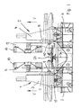
- the machine tool group has two processing units 1, 2, which face each other at a distance.
- the two processing units 1, 2 are advantageously the same design, but arranged mirror-symmetrically to each other. Of course, the processing units 1, 2 but also be designed differently.
- Each processing unit 1, 2 has a stand 3, 4, which is mounted on a bed 5, 6.
- a respective carriage 7, 8 is arranged to be movable in the Y direction.
- Each carriage 7, 8 carries a spindle 9, 10, which extends in the Z direction.
- the spindles 9, 10 tools can be used for machining a workpiece or a group of workpieces. By preferably a quill movement, the spindles 9, 10 are moved in the Z direction.
- 1 and 2 are two positions of the spindles 9, 10 located. With the carriage 7, 8, the spindles 9, 10 can be adjusted in the Y direction. An adjustment in the X direction is possible because the stands 3, 4 are movable on the bed 5, 6 in the X direction.
- the two processing units 1, 2 are identical, a left or right design is not required. Due to the described possibilities of movement, the two spindles 7, 8 can be moved in a right-angled Cartesian coordinate system in the X, Y and Z axes.
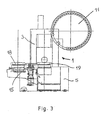
- Each processing unit 1, 2 is provided with a tool magazine 11, 12, which in the embodiment of the Fig. 1 to 3 Round magazines are, which are rotatably mounted about an axis lying in the Z direction on the stand 3, 4 of the respective processing unit 1, 2.
- the two tool magazines 11, 12 are how it looks Fig. 1 results, arranged on the mutually facing sides of the processing units 1, 2.
- tools 13, 14 are housed, which can be changed in a known manner with a (not shown) changer in the pick-up process in the respective spindle 9, 10.
- the tool magazines 11, 12 are formed in a known manner and are rotatably driven by a motor.
- the axes of rotation of the tool magazines 11, 12 are provided in the upper region of the stands 3, 4 ( Fig. 1 ).
- the tool magazines 11, 12 may be rotatably mounted directly on the uprights 3, 4. But it is also possible to store the tool magazines 11, 12 on additional stands. These additional stands are then advantageously firmly connected to the uprights 3, 4, so that both stands can be moved together in the X direction.
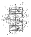
- a rotary table 15 which is rotatable about a vertical axis 16. It lies, seen in plan view ( Fig. 2 ), with distance to the central axis 17 of the working area between the two processing units 1, 2. As a result, the rotary table 15 projects laterally beyond the two processing units 1, 2.
- rotary table 15 diametrically opposite each other two smaller rotary tables 18 and 19 are provided which are rotatable about mutually parallel, lying in the Y-direction axes 20 and 21.
- the axes of rotation 20, 21 each have the same distance from the axis of rotation 16 of the rotary table 15.
- the two rotary tables 18, 19 on both sides of a partition 22 which extends in the vertical direction and is arranged diametrically on the rotary table 15.
- partition wall 22 of the rotary table 15 is divided into two approximately semicircular areas, in each of which a rotary table 18 and 19 is located.
- pallets 23, 24 are constructed as workpiece carriers.
- a workpiece carrier is located in each case in the processing station 25 between the two processing units 1, 2, while the other workpiece carrier can be loaded and unloaded on a set-up station 26.
- the processing station 25 and the set-up station 26 are separated from each other by the partition 22.
- the partition 22 prevents chips from reaching the processing station 25 in the area of the set-up station 26.
- more than two further rotary tables 18, 19 can be mounted on it.
- the rotary tables 18, 19 may be formed as part tables or equipped with a NC rotary axis.
- the rotary tables 18, 19 are rotatably driven about their axes 20, 21. Since these rotary tables 18, 19 are mounted on the rotary table 15, the rotary tables 18, 19 perform a planetary movement about the axis 17 located centrally between the two processing units 1, 2. On the exchangeable pallets 23, 24 different workpieces can be clamped, so that in the processing station 25 successively different workpieces can be edited.
- the spindles 9, 10 of the processing units 1, 2 are advantageously in the described three-axis Cartesian coordinate system NC controlled movable. It is additionally possible to provide further degrees of freedom in the form of twists, so that the tools used in the spindles 9, 10 can also occupy angular positions with respect to the X, Y, Z space.
- the processing station 25 between the two processing units 1, 2 is separated by the partition wall 22 against the set-up station 26.
- the partition wall 22 extends at a distance from the central center axis 17 of the processing station 25.
- setup station 26, which is opposite the processing station 25, the necessary loading / set-up and unloading operations can be made while the workpiece located in the processing station 25 with the in the Spindles 9, 10 tools used is processed.
- the processing station 25, which forms the working space of the machine tool group, is advantageously formed by protective doors (not shown) for the operator as a chip collecting space.
- the exchangeable pallets 23, 24 are advantageously conveyed by an automatic loading device.
- spatial turrets 27 can be inserted into the spindles 9, 10.
- spindles 9, 10 multi-spindle heads 28 (FIG. Fig. 5 ) to clamp.
- the various tools of the turret 27 and the multi-spindle head 28 the workpieces can be optimally processed.
- individual tools can also be used in the spindles 9, 10. The respectively required tools or heads are removed from the respective processing unit 1, 2 associated tool magazines 11, 12.
- the spindle axes 29, 30 ( Fig. 2 ) of the processing units 1, 2 form the tangents of an imaginary arc of a circle whose common centers lie on the axis 16 of the rotary table 15.
- the processing units 1, 2 are adjusted in terms of work area, speed of the linear and rotary axes and in terms of performance to the different, to be done editing tasks.
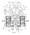
- Fig. 6 shows the connection of the two processing units 1, 2 to a circular accumulator 31, which can be rotatably driven about a vertical axis 32.
- the axis of rotation 32 is located in the area next to the two processing units 1, 2.
- the axes of rotation are 32 and 16 of the circular memory 31 and the rotary table 15 in a common vertical plane 33 which extends centrally between the two processing units 1, 2.
- the axes of rotation are 20 and 21 of the rotary tables 18, 19 in the vertical plane 33 when the workpiece is processed in the processing station 25.
- the round memory 31 extends to close to the vertical axis of rotation 16 of the rotary table 15.
- a plurality of removable pallets 34 are mounted, on which the workpieces to be machined can be clamped.
- the set-up station 26 is no longer in the amount of the processing station 25, but in addition to the processing unit 1.
- the corresponding tool is clamped on the removable pallet 34 '.
- the change pallet 34 'with the clamped workpiece is then brought to the round store 31 at the point 34 ", from which the respective change pallet arrives after a corresponding rotation of the round store 31 about the axis 32 to the rotary table 15. From it the change pallet 34 is taken over.
- the change pallet 34 with the clamped workpiece is brought into the processing station 25 between the two processing units 1, 2.
- the workpiece previously machined by the tools of the spindle 9, 10 is here together with the associated change pallet
- the interchangeable pallet with the machined workpiece passes into the set-up station 26.
- four interchangeable pallets 34 are arranged at an angular distance of 90 ° to one another on the circular accumulator 31. That's why the round spokes r 31 each rotated by 90 ° to successively bring the respective change pallets to the rotary table 15. It is rotated in each case by 180 ° about its axis 16 in order to transport the change pallet with the workpiece into the processing station 25. In the 180 ° rotation of the rotary table 15, the removable pallet with the machined workpiece is transported to the round memory 31.
- Fig. 7 shows by way of example the coupling of the machine tool group to a linear linkage 35.
- the machine tool group with the two processing units 1, 2 is located next to the linear linkage 35. It has a track 36 on which a carriage 37 is movable with a linear drive. On the carriage 37, a removable pallet 38 can be mounted on which the respective workpiece to be machined can be clamped.
- a pallet store 39 On the side facing away from the machine tool group side of the web 36 is a pallet store 39, in the direction of travel of the carriage 37 successively pallets 38 are mounted.
- the carriage 37 is provided with perpendicular to its direction of travel guides 40, via which the pallets 38 can be easily transported from the pallet storage 39 on the carriage 37 and from there to the rotary table 15.
- the machine tool group is the same, as based on the Fig. 1 to 3 has been explained in detail.
- Fig. 8 and 9 have the processing units 1, 2 chain magazines 11a, 12a as a tool magazine, which are formed with one or more loops.
- the tools 13, 14 are by means of a one- or two-armed pivoting gripper 41 ( Fig. 9 ) between the chain magazine 11a, 12a and the respective spindle 9, 10 of the processing units 1, 2 replaced.
- the use of a two-armed gripper 41 has the advantage that in one operation the tool located in the respective spindle 9, 10 and in the respective chain magazine 11a, 12a can be detected and exchanged for one another after a 180 ° turn.
- the machine tool group is the same design as the embodiment of the Fig. 1 to 3 ,
- a high throughput speed and productivity is achieved by the simultaneous engagement of a plurality of processing units 1, 2 or the tools clamped in their spindles 9, 10 on the workpiece. Position deviations of the workpiece between different processing stations can not occur because the workpiece does not leave the area between the two processing units 1, 2 during processing.
- the working forces acting on the workpiece, which lead to deformations, are at least partially compensated, since the processing units 1, 2 and thus their spindles 9, 10 are located on opposite sides of the workpiece to be machined. All machining movements are performed by the tool. In the X direction, the stand 3, 4 of the respective processing unit 1, 2 is moved. In the Y direction, the machining movement by moving the spindle 9, 10 carrying carriage 7, 8.
- the machining movement in the Z direction is preferably carried out by the quill movement of the spindles 9, 10. Since the machining movements are performed by the tool, different workpiece masses can Dynamic movement between tool and workpiece does not influence unfavorably dynamically.
- measuring, checking, loading, tensioning, relaxing and unloading can be conveniently carried out at the stationary setup station.
- the two processing units 1, 2 can be manufactured inexpensively with identical design. Have the two processing units 1, 2 different training, they can be optimally adapted to specific processing tasks.
- the processing machines 1, 2 can operate sequentially, e.g. at each different angle settings of the rotary tables 18, 19.
Landscapes
- Engineering & Computer Science (AREA)
- Mechanical Engineering (AREA)
- Feeding Of Workpieces (AREA)
- Multi-Process Working Machines And Systems (AREA)
- Perforating, Stamping-Out Or Severing By Means Other Than Cutting (AREA)
- Automatic Tool Replacement In Machine Tools (AREA)
- Inorganic Insulating Materials (AREA)
Claims (11)
- Disposition de machine-outils avec deux unités d'usinage (1, 2), opposées l'une par rapport à l'autre, comprenant respectivement une broche (9, 10) pour outils, avec lesquelles au moins une pièce est usinable, laquelle est supportée par un dispositif de fixation, monté sur une palette (23, 24; 34), laquelle est prévue sur un support de table circulaire (15) mobile autour d'un axe vertical (16) et est située dans une station d'usinage (25), laquelle est disposée entre les deux unités d'usinage (1, 2) , à l'aide des outils desquelles la pièce est usinable simultanément,
caractérisée en ce que la palette (23, 24; 34) est transportable par l'intermédiaire du support de la table circulaire (15) dans la station d'usinage (25) entre les deux unités d'usinage de préférence de forme identique et que l'axe de rotation (16) du support de table circulaire (15) est prévu à distance d'un axe central (17) situé entre les deux unités d'usinage (1, 2) et est situé dans la zone entre les deux unités 'usinage (1, 2) et que l'axe de rotation (16) du support de table circulaire (15) et l'axe central (17) sont situés dans un plan vertical (33) qui se trouve centriquement entre les deux unités d'usinage (1, 2) et que sur le support de table circulaire (15) au moins deux tables circulaires (18, 19) sont montées en position couchée à distance l'une à l'autre, lesquelles sont opposées diamétralement par rapport au support de table circulaire (15) et sont rotatives sur des axes parallèles (20, 21) l'un à l'autre, lesquels sont situés parallèlement à l'axe de rotation (16) du support de la table circulaire (15) et sont à distance égale de l'axe de rotation (16). - Disposition de machines-outils selon revendication 1,
caractérisée en ce que les axes de rotation (16; 20, 21) du support de table circulaire (15) et des tables circulaires (18, 19) recevant les palettes (23, 24; 34) et avantageusement formées comme tables graduées, sont situées dans un plan commun et que de préférence les tables circulaires (18, 19) sont munies d'un axe de rotation de commande numérique et que les palettes (23, 24; 34) sont transportables par une installation de chargement automatique (31, 35). - Disposition de machines-outils selon une des revendications 1 à 2,
caractérisée en ce que sur le support de table circulaire (15) une paroi de séparation (22), est disposée debout laquelle sépare la station d'usinage (25) d'un poste de mise en route (26) ou d'un magasin de palettes (31). - Disposition de machines-outils selon une des revendications 1 à 3,
caractérisée en ce que au moins une, de préférence les deux unités d'usinage (1, 2) sont mobiles en plusieurs degrés de liberté par commande numérique, de préférence dans un système de coordination triaxial cartésien et qu'avantageusement au moins l'une, de préférence les deux unités d'usinage (1, 2) comprennent des degrés de liberté rotatifs. - Disposition de machines-outils selon une des revendications 1 à 4,
caractérisée en ce que le support de table circulaire (15) est formé comme changeur de palettes et/ou la station d'usinage (25) est formée comme espace collecteur de copeaux avec des portes de protection. - Disposition de machines-outils selon une des revendications 1 à 5,
caractérisée en ce que dans les broches (9, 10) des unités d'usinage (1, 2) des tourelles revolver tridimensionnelles (27) et/ou des têtes multibroches (28) sont insérables et que de préférence des magasins d'outils (11, 12) avantageusement rotatifs sur essieux horizontaux et/ou des magasins d'outils (11a, 12a) construits comme magasin à chaîne avec une ou plusieurs boucles sont adjoints aux broches (9, 10) et que de préférence les outils sont échangés à l'aide d'un preneur (41) entre un ou deux bras pivotable entre le magasin et les broches (9, 10) des unités d'usinage (1, 2). - Disposition des machines-outils selon une des revendications 1 à 6,
caractérisée en ce que les essieux (29, 30) des broches (9, 10) représentent des tangentes d'une famille de cercles imaginaire dont le centre commun est situé dans l'essieu (16) du support de table circulaire (15). - Disposition des machines-outils selon une des revendications 1 à 7,
caractérisée en ce que les unités d'usinage (1, 2) sont adaptable à des tâches d'usinage différentes par rapport à la zone de travail, à la vitesse d'essieux linéaires et rotatifs ainsi qu'à la puissance. - Disposition des machines-outils selon une des revendications 1 à 8,
caractérisée en ce que le magasin des palettes (31) est rotatif sur un essieu (32), situé parallèlement par rapport à l'essieu (16) du support de table circulaire (15), l'essieu (32) étant situé avantageusement avec l'essieu rotatif (16) du support de table circulaire (15) et les essieux rotatifs (20, 21) des tables circulaires (18, 19) dans un plan commun (33), se déroulant avantageusement à travers la station d'usinage (25). - Disposition de machines-outils selon une des revendications 1 à 9,
caractérisée en ce que les unités d'usinage (1, 2) sont entraînables indépendamment l'une de l'autre et/ou travaillent séquentiellement, par exemple sur des positions angulaires respectivement différentes des tables circulaires (18, 19). - Disposition des machines-outils selon une des revendications 1 à 10,
caractérisée en ce que les palettes (38) sont emmagasinables dans un magasin linéaire (39) et que de préférence entre le magasin linéaire (39) et les unités d'usinage (1, 2) un convoyeur (36, 37, 40) est ménagé pour les palettes (38).
Applications Claiming Priority (2)
| Application Number | Priority Date | Filing Date | Title |
|---|---|---|---|
| DE19744157 | 1997-10-07 | ||
| DE19744157A DE19744157A1 (de) | 1997-10-07 | 1997-10-07 | Werkzeugmaschinengruppe mit zwei einander gegenüberstehenden Bearbeitungseinheiten |
Publications (4)
| Publication Number | Publication Date |
|---|---|
| EP0908269A2 EP0908269A2 (fr) | 1999-04-14 |
| EP0908269A3 EP0908269A3 (fr) | 2002-05-08 |
| EP0908269B1 EP0908269B1 (fr) | 2004-01-14 |
| EP0908269B2 true EP0908269B2 (fr) | 2009-05-27 |
Family
ID=7844773
Family Applications (1)
| Application Number | Title | Priority Date | Filing Date |
|---|---|---|---|
| EP98118692A Expired - Lifetime EP0908269B2 (fr) | 1997-10-07 | 1998-10-02 | Disposition de machines-outils avec deux unités d'usinage opposées |
Country Status (3)
| Country | Link |
|---|---|
| EP (1) | EP0908269B2 (fr) |
| AT (1) | ATE257757T1 (fr) |
| DE (2) | DE19744157A1 (fr) |
Cited By (1)
| Publication number | Priority date | Publication date | Assignee | Title |
|---|---|---|---|---|
| WO2011021215A3 (fr) * | 2009-08-05 | 2011-05-05 | Kennametal India Limited | Module de colonne multiaxial, procédé d'échange d'outils, et procédé d'assemblage |
Families Citing this family (24)
| Publication number | Priority date | Publication date | Assignee | Title |
|---|---|---|---|---|
| EP1346788A3 (fr) * | 2002-03-22 | 2003-10-22 | GROB-Werke Burkhart Grob e.K. | Centre d'usinage |
| DE10302985A1 (de) * | 2002-03-22 | 2003-10-23 | Grob Werke Burkhart Grob Ek | Bearbeitungszentrum |
| DE10224577A1 (de) | 2002-06-03 | 2003-12-11 | Kessler Kg Maschf | Vorrichtung zur Bearbeitung von Werkstücken sowie Maschinenanordnung hierzu |
| DE10231017A1 (de) * | 2002-07-09 | 2004-04-08 | Burkhart Grob E.K. Grob-Werke | Transferstraße |
| DE10235518B4 (de) * | 2002-08-05 | 2007-01-11 | Emag Holding Gmbh | Verfahren und Vorrichtung zur Werkstück-Bearbeitung |
| DE10257151A1 (de) * | 2002-12-05 | 2004-06-24 | Grob-Werke Burkhart Grob E.K. | Werkzeugmaschine |
| DE10258734A1 (de) * | 2002-12-16 | 2004-06-24 | Alfing Kessler Sondermaschinen Gmbh | Werkzeugmaschine |
| DE10345119A1 (de) * | 2003-04-28 | 2004-11-18 | Grob-Werke Burkhart Grob E.K. | Bearbeitungsmaschine |
| DE10334285A1 (de) * | 2003-07-25 | 2005-02-24 | Grob-Werke Burkhart Grob E.K. | Bearbeitungsmaschine mit zwei Bearbeitungseinheiten |
| DE10349697B4 (de) * | 2003-10-24 | 2007-03-29 | Daimlerchrysler Ag | Bearbeitungssystem zur spanenden Bearbeitung von Zylinderköpfen |
| DE10358381A1 (de) * | 2003-12-11 | 2005-07-07 | Grob-Werke Burkhart Grob E.K. | Bearbeitungszentrum mit insbesondere vertikal angeordneten Bearbeitungsspindeln |
| DE202007018833U1 (de) * | 2006-11-13 | 2009-06-10 | Iemca Giuliani Macchine Italia S.P.A., Faenza | Werkzeugmaschine |
| TR200809177U (tr) * | 2008-11-28 | 2009-04-21 | Di̇ri̇nler Maki̇na Sanayi̇ Ve Ti̇caret Anoni̇m Şi̇rketi̇ | İki kafalı ve altı eksenli CNC yatay freze. |
| EP2233247B1 (fr) * | 2009-03-27 | 2011-08-24 | Emissa S.A. | Centre d'usinage autonome de haute production à prise de pièce verticale |
| DE102010028032B4 (de) * | 2010-04-21 | 2012-02-09 | Felsomat Gmbh & Co. Kg | Werkzeugmaschine mit zusätzlichem Zuganker |
| DE102014100212B4 (de) | 2013-01-11 | 2018-04-05 | Bumotec Sa | Bearbeitungseinheit mit zwei Arbeitsspindeln und Fertigungsstraße |
| DE202013000225U1 (de) | 2013-01-11 | 2014-04-14 | Bumotec Sa | Bearbeitungseinheit mit zwei Arbeitsspindeln |
| JP6351712B2 (ja) * | 2013-06-11 | 2018-07-04 | エーリコン テクスティル ゲゼルシャフト ミット ベシュレンクテル ハフツング ウント コンパニー コマンディートゲゼルシャフトOerlikon Textile GmbH & Co. KG | テクスチャリング加工機 |
| EP3048182B1 (fr) | 2015-01-20 | 2018-11-21 | Sturm Maschinen- & Anlagenbau GmbH | Installation et procédé de revêtement métallique d'une pièce usinée |
| DE102015108194A1 (de) * | 2015-05-22 | 2016-11-24 | Ffg Werke Gmbh | Werkzeugmaschine mit horizontalen Arbeitsspindeln |
| DE102015121925A1 (de) | 2015-09-24 | 2017-03-30 | Alfing Kessler Sondermaschinen Gmbh | Werkzeugmaschine |
| CN114192903A (zh) * | 2021-12-17 | 2022-03-18 | 浙江博亚精密机械有限公司 | 螺纹、螺旋面以及渐开线面转子加工装置 |
| JP7750803B2 (ja) * | 2022-08-03 | 2025-10-07 | 株式会社スギノマシン | インデックス加工機 |
| JP2025064130A (ja) * | 2023-10-05 | 2025-04-17 | 株式会社スギノマシン | 加工システム |
Citations (1)
| Publication number | Priority date | Publication date | Assignee | Title |
|---|---|---|---|---|
| EP0172299A1 (fr) † | 1984-07-24 | 1986-02-26 | Maschinenfabrik Diedesheim GmbH | Machine-outil |
Family Cites Families (3)
| Publication number | Priority date | Publication date | Assignee | Title |
|---|---|---|---|---|
| US4485911A (en) * | 1982-01-26 | 1984-12-04 | The Budd Company | Transfer machine |
| FR2631869A1 (fr) * | 1988-05-25 | 1989-12-01 | Somex Sa | Machine-outil modulaire comportant au moins une unite d'usinage |
| US5265497A (en) * | 1992-09-08 | 1993-11-30 | Cincinnati Milacron Inc. | Guard for operator access station |
-
1997
- 1997-10-07 DE DE19744157A patent/DE19744157A1/de not_active Withdrawn
-
1998
- 1998-10-02 EP EP98118692A patent/EP0908269B2/fr not_active Expired - Lifetime
- 1998-10-02 AT AT98118692T patent/ATE257757T1/de not_active IP Right Cessation
- 1998-10-02 DE DE59810579T patent/DE59810579D1/de not_active Expired - Fee Related
Patent Citations (1)
| Publication number | Priority date | Publication date | Assignee | Title |
|---|---|---|---|---|
| EP0172299A1 (fr) † | 1984-07-24 | 1986-02-26 | Maschinenfabrik Diedesheim GmbH | Machine-outil |
Cited By (1)
| Publication number | Priority date | Publication date | Assignee | Title |
|---|---|---|---|---|
| WO2011021215A3 (fr) * | 2009-08-05 | 2011-05-05 | Kennametal India Limited | Module de colonne multiaxial, procédé d'échange d'outils, et procédé d'assemblage |
Also Published As
| Publication number | Publication date |
|---|---|
| DE59810579D1 (de) | 2004-02-19 |
| EP0908269A2 (fr) | 1999-04-14 |
| ATE257757T1 (de) | 2004-01-15 |
| EP0908269B1 (fr) | 2004-01-14 |
| DE19744157A1 (de) | 1999-04-08 |
| EP0908269A3 (fr) | 2002-05-08 |
Similar Documents
| Publication | Publication Date | Title |
|---|---|---|
| EP0908269B2 (fr) | Disposition de machines-outils avec deux unités d'usinage opposées | |
| DE3427245C2 (de) | Werkzeugmaschine | |
| DE19514058C2 (de) | Drehmaschine mit mehreren Spindeln | |
| EP2812152B1 (fr) | Machine de rodage à plusieurs postes de travail et table rotative | |
| DE19533320C2 (de) | Rundtaktmaschine | |
| EP1871570B1 (fr) | Châine de production servant à usiner des pièces avec souplesse | |
| EP0885686B1 (fr) | Centre d'usinage | |
| DE19521846A1 (de) | Numerisch gesteuerte Bearbeitungsmaschine | |
| EP1294531A1 (fr) | Dispositif d'usinage de pieces au moyen d'au moins une machine-outil | |
| EP3784432B1 (fr) | Machine-outil avec une broche de travail montee sur une surface inclinee | |
| EP3641972B1 (fr) | Systeme de déplacement et machine à tailler les engrenages | |
| DE8915924U1 (de) | Bohr- und Fräswerk | |
| DE19904859A1 (de) | Drehmaschine mit zwei Werkstückspindeln | |
| EP1413395A1 (fr) | Machine-outil | |
| DE19800034C2 (de) | Werkzeugmaschine für Bearbeitungswerkzeuge aus der Gruppe Schleifkörper und Fräser | |
| DE4015570A1 (de) | Werkzeugmaschine, insbesondere vertikal-schleifmaschine und verfahren zum bearbeiten von werkstuecken mit dieser maschine | |
| DE10034973A1 (de) | Universalmaschine | |
| EP0130309A1 (fr) | Machines à travailler le bois | |
| EP0612278B1 (fr) | Tour automatique multibroche | |
| EP1459838B1 (fr) | Centre d'usinage vertical | |
| EP1294530A2 (fr) | Machine-outil destinee a l'usinage au moins triaxial de pieces | |
| DE19803563C1 (de) | Werkzeugmaschine, insbesondere Drehmaschine mit wenigstens einer hängend angeordneten horizontalen Arbeitsspindel | |
| DE10058627A1 (de) | Drehmaschine | |
| DE10144679A1 (de) | Bearbeitungszentrum | |
| EP1647358B1 (fr) | Machine de traitement plusieurs faces de la pièce et dispositif pour le positionnement de la pièce |
Legal Events
| Date | Code | Title | Description |
|---|---|---|---|
| PUAI | Public reference made under article 153(3) epc to a published international application that has entered the european phase |
Free format text: ORIGINAL CODE: 0009012 |
|
| AK | Designated contracting states |
Kind code of ref document: A2 Designated state(s): AT BE CH CY DE DK ES FI FR GB GR IE IT LI LU MC NL PT SE |
|
| AX | Request for extension of the european patent |
Free format text: AL;LT;LV;MK;RO;SI |
|
| PUAL | Search report despatched |
Free format text: ORIGINAL CODE: 0009013 |
|
| AK | Designated contracting states |
Kind code of ref document: A3 Designated state(s): AT BE CH CY DE DK ES FI FR GB GR IE IT LI LU MC NL PT SE |
|
| AX | Request for extension of the european patent |
Free format text: AL;LT;LV;MK;RO;SI |
|
| RIC1 | Information provided on ipc code assigned before grant |
Free format text: 7B 23Q 39/02 A, 7B 23Q 37/00 B, 7B 23Q 7/02 B |
|
| 17P | Request for examination filed |
Effective date: 20020912 |
|
| 17Q | First examination report despatched |
Effective date: 20021029 |
|
| AKX | Designation fees paid |
Designated state(s): AT DE ES FR GB IT SE |
|
| GRAP | Despatch of communication of intention to grant a patent |
Free format text: ORIGINAL CODE: EPIDOSNIGR1 |
|
| GRAS | Grant fee paid |
Free format text: ORIGINAL CODE: EPIDOSNIGR3 |
|
| GRAA | (expected) grant |
Free format text: ORIGINAL CODE: 0009210 |
|
| AK | Designated contracting states |
Kind code of ref document: B1 Designated state(s): AT DE ES FR GB IT SE |
|
| PG25 | Lapsed in a contracting state [announced via postgrant information from national office to epo] |
Ref country code: IT Free format text: LAPSE BECAUSE OF FAILURE TO SUBMIT A TRANSLATION OF THE DESCRIPTION OR TO PAY THE FEE WITHIN THE PRE;WARNING: LAPSES OF ITALIAN PATENTS WITH EFFECTIVE DATE BEFORE 2007 MAY HAVE OCCURRED AT ANY TIME BEFORE 2007. THE CORRECT EFFECTIVE DATE MAY BE DIFFERENT FROM THE ONE RECORDED.SCRIBED TIME-LIMIT Effective date: 20040114 Ref country code: GB Free format text: LAPSE BECAUSE OF FAILURE TO SUBMIT A TRANSLATION OF THE DESCRIPTION OR TO PAY THE FEE WITHIN THE PRESCRIBED TIME-LIMIT Effective date: 20040114 Ref country code: FR Free format text: LAPSE BECAUSE OF FAILURE TO SUBMIT A TRANSLATION OF THE DESCRIPTION OR TO PAY THE FEE WITHIN THE PRESCRIBED TIME-LIMIT Effective date: 20040114 |
|
| REG | Reference to a national code |
Ref country code: GB Ref legal event code: FG4D Free format text: NOT ENGLISH |
|
| REG | Reference to a national code |
Ref country code: IE Ref legal event code: FG4D Free format text: GERMAN |
|
| REF | Corresponds to: |
Ref document number: 59810579 Country of ref document: DE Date of ref document: 20040219 Kind code of ref document: P |
|
| PG25 | Lapsed in a contracting state [announced via postgrant information from national office to epo] |
Ref country code: SE Free format text: LAPSE BECAUSE OF FAILURE TO SUBMIT A TRANSLATION OF THE DESCRIPTION OR TO PAY THE FEE WITHIN THE PRESCRIBED TIME-LIMIT Effective date: 20040414 |
|
| PG25 | Lapsed in a contracting state [announced via postgrant information from national office to epo] |
Ref country code: ES Free format text: LAPSE BECAUSE OF FAILURE TO SUBMIT A TRANSLATION OF THE DESCRIPTION OR TO PAY THE FEE WITHIN THE PRESCRIBED TIME-LIMIT Effective date: 20040425 |
|
| GBV | Gb: ep patent (uk) treated as always having been void in accordance with gb section 77(7)/1977 [no translation filed] |
Effective date: 20040114 |
|
| REG | Reference to a national code |
Ref country code: IE Ref legal event code: FD4D |
|
| PG25 | Lapsed in a contracting state [announced via postgrant information from national office to epo] |
Ref country code: AT Free format text: LAPSE BECAUSE OF NON-PAYMENT OF DUE FEES Effective date: 20041002 |
|
| PLBQ | Unpublished change to opponent data |
Free format text: ORIGINAL CODE: EPIDOS OPPO |
|
| PLBI | Opposition filed |
Free format text: ORIGINAL CODE: 0009260 |
|
| PLAX | Notice of opposition and request to file observation + time limit sent |
Free format text: ORIGINAL CODE: EPIDOSNOBS2 |
|
| 26 | Opposition filed |
Opponent name: ALFING KESSLER SONDERMASCHINEN GMBH Effective date: 20041014 |
|
| EN | Fr: translation not filed | ||
| PLAX | Notice of opposition and request to file observation + time limit sent |
Free format text: ORIGINAL CODE: EPIDOSNOBS2 |
|
| PLBB | Reply of patent proprietor to notice(s) of opposition received |
Free format text: ORIGINAL CODE: EPIDOSNOBS3 |
|
| PLAU | Termination of opposition procedure: information related to despatch of decision deleted |
Free format text: ORIGINAL CODE: EPIDOSDOPC1 |
|
| PLBD | Termination of opposition procedure: decision despatched |
Free format text: ORIGINAL CODE: EPIDOSNOPC1 |
|
| PLAB | Opposition data, opponent's data or that of the opponent's representative modified |
Free format text: ORIGINAL CODE: 0009299OPPO |
|
| PLAO | Information deleted related to despatch of communication that opposition is rejected |
Free format text: ORIGINAL CODE: EPIDOSDREJ1 |
|
| PLCK | Communication despatched that opposition was rejected |
Free format text: ORIGINAL CODE: EPIDOSNREJ1 |
|
| PUAH | Patent maintained in amended form |
Free format text: ORIGINAL CODE: 0009272 |
|
| STAA | Information on the status of an ep patent application or granted ep patent |
Free format text: STATUS: PATENT MAINTAINED AS AMENDED |
|
| 27A | Patent maintained in amended form |
Effective date: 20090527 |
|
| AK | Designated contracting states |
Kind code of ref document: B2 Designated state(s): AT DE ES FR GB IT SE |
|
| PGFP | Annual fee paid to national office [announced via postgrant information from national office to epo] |
Ref country code: DE Payment date: 20081222 Year of fee payment: 11 |
|
| REG | Reference to a national code |
Ref country code: ES Ref legal event code: FD2A Effective date: 20041004 |
|
| PG25 | Lapsed in a contracting state [announced via postgrant information from national office to epo] |
Ref country code: DE Free format text: LAPSE BECAUSE OF NON-PAYMENT OF DUE FEES Effective date: 20100501 |