EP0908336A2 - Installation de climatisation ou de chauffage pour véhicules de grand volume - Google Patents
Installation de climatisation ou de chauffage pour véhicules de grand volume Download PDFInfo
- Publication number
- EP0908336A2 EP0908336A2 EP98116155A EP98116155A EP0908336A2 EP 0908336 A2 EP0908336 A2 EP 0908336A2 EP 98116155 A EP98116155 A EP 98116155A EP 98116155 A EP98116155 A EP 98116155A EP 0908336 A2 EP0908336 A2 EP 0908336A2
- Authority
- EP
- European Patent Office
- Prior art keywords
- air
- opening
- guide box
- air guide
- recirculating
- Prior art date
- Legal status (The legal status is an assumption and is not a legal conclusion. Google has not performed a legal analysis and makes no representation as to the accuracy of the status listed.)
- Granted
Links
Images


Classifications
-
- B—PERFORMING OPERATIONS; TRANSPORTING
- B60—VEHICLES IN GENERAL
- B60H—ARRANGEMENTS OF HEATING, COOLING, VENTILATING OR OTHER AIR-TREATING DEVICES SPECIALLY ADAPTED FOR PASSENGER OR GOODS SPACES OF VEHICLES
- B60H1/00—Heating, cooling or ventilating devices
- B60H1/00457—Ventilation unit, e.g. combined with a radiator
- B60H1/00471—The ventilator being of the radial type, i.e. with radial expulsion of the air
-
- B—PERFORMING OPERATIONS; TRANSPORTING
- B60—VEHICLES IN GENERAL
- B60H—ARRANGEMENTS OF HEATING, COOLING, VENTILATING OR OTHER AIR-TREATING DEVICES SPECIALLY ADAPTED FOR PASSENGER OR GOODS SPACES OF VEHICLES
- B60H1/00—Heating, cooling or ventilating devices
- B60H1/00357—Air-conditioning arrangements specially adapted for particular vehicles
- B60H1/00371—Air-conditioning arrangements specially adapted for particular vehicles for vehicles carrying large numbers of passengers, e.g. buses
-
- B—PERFORMING OPERATIONS; TRANSPORTING
- B60—VEHICLES IN GENERAL
- B60H—ARRANGEMENTS OF HEATING, COOLING, VENTILATING OR OTHER AIR-TREATING DEVICES SPECIALLY ADAPTED FOR PASSENGER OR GOODS SPACES OF VEHICLES
- B60H1/00—Heating, cooling or ventilating devices
- B60H1/00007—Combined heating, ventilating, or cooling devices
- B60H1/00207—Combined heating, ventilating, or cooling devices characterised by the position of the HVAC devices with respect to the passenger compartment
- B60H2001/00235—Devices in the roof area of the passenger compartment
Definitions
- the invention relates to an air conditioning or heating system for Large-capacity vehicles, in particular for buses, according to the Preamble of claim 1.
- the invention has for its object in a climate or Heating system of the type mentioned the efficiency ventilation and ventilation with heated or to significantly improve cooled air.
- the air conditioning or heating system Advantage of the separate skimming and processing of fresh air and recirculated air in parallel air duct boxes, both of which lead to the interior of the vehicle greater air flow both with ventilation and with Ventilation with conditioned or unconditioned air is achieved so that a faster air exchange is possible without the fan noise in an unacceptable way increase.
- Better air circulation results in one Long-distance limousine to a more pleasant in the long term climate feeling and improves the well-being of the passengers considerably.
- the air intake and conditioning agents in everyone Air duct box a blower and a heat exchanger and / or an evaporator of a refrigeration unit.
- in the Vehicle interior is a return air opening and in which the Recirculating air duct box an exhaust air opening provided, via the air in the vehicle environment can flow out.
- Control means in the form of swiveling Air flaps are used to selectively close and release the Air vents. Because of these constructive measures, it is by switching on the two fans and selective control of the individual air openings possible, to implement different operating modes, all in all one enable optimal air conditioning of the open-top van.
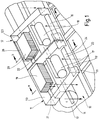
- Heating system is for use in a large capacity vehicle, e.g. Omnibus, designed and is on the roof 10 of the Large vehicle arranged. It shows two of each other separate air duct boxes 11, 12 on side by side are arranged and on the output side in an air duct 13 open out along the roof 10 of the MPV extends and with air outlets 14 to the vehicle interior is provided.
- the air outlets 14 can be at a distance channel openings arranged from each other or - as this in Fig. 1 is shown - from a continuous slot be formed.
- One air duct box 11, in the following Fresh air guide box 11 is called, on the input side a fresh air opening 15 connected to the vehicle surroundings, while the other air duct box 12, in the following air duct box 12 called, at a circulating air opening 16 for Vehicle interior is connected.
- Every air duct box 11, 12 is with a blower 17 or 18 and a heat exchanger 19 or 20 equipped, the suction openings of the blower 17, 18 of the fresh air opening 15 and the recirculating air opening 16 and the outlets of the blowers 17, 18 to the heat exchangers 19, 20 are turned.
- the heat exchangers 19, 20 are known Way of that heated in the internal combustion engine Cooling water flowed through, the heat output by Throttling of the cooling water flow can be set.
- the heat exchangers are 19.20 ⁇ m 45 ° inclined so that the fan 17 or 18th generated air flow flows through the heat exchanger 19 or 20 and via the mouth opening 21 or 22 in the bottom 112 or 122 of the air guide boxes 11, 12 enters the air duct 13.
- the air duct 13 then distributes the air outlets 14 Air in the vehicle interior.
- FIGS. 2-4 and not further in FIG. 1 is shown, is in the roof 10 of the MPV Return air opening 23 is provided, which is congruent with a Air inlet 24 is arranged in the fresh air guide box 11.
- the air inlet 24 is close to one below the Fresh air opening 15 arranged air outlet 25 in Fresh air guide box 11, the fresh air opening 15 and the air outlet 25 in one side wall 111 of the Fresh air guide box 11 and the air inlet 24 in the the roof 10 overlying floor 112 of the fresh air guide box 11 is arranged.
- One inside the Fresh air guide box 11 extending wall part 114 is like this arranged that the air inlet 24 and the return air opening 23rd is shielded from the fresh air opening 15 and communicates exclusively with the air outlet 25.
- the the side wall 111 opposite side wall 113 of the Fresh air guide box 11 is shot.
- the Recirculating air guide box 12 is in the mouth opening 22nd the nearby side wall 123 of the circulating air guide box 12 an exhaust air opening 26 is provided, through which the fan 18 through the air circulation opening 16 from the vehicle interior sucked-in air can be blown out into the vehicle environment can.
- the side wall 121 opposite the side wall 123 of the circulating air guide box 12 is closed.
- control means in the form of air flaps for Control of the air openings, such as fresh air opening 15, Air outlet 25, air circulation opening 16, mouth opening 22 and Exhaust air opening 26 is provided.
- air flaps for Control of the air openings, such as fresh air opening 15, Air outlet 25, air circulation opening 16, mouth opening 22 and Exhaust air opening 26 is provided.
- the fresh air guide box 11 a swiveling, two-winged first Backflow flap 27 arranged so that it is in a first Pivot position fresh air opening 15 and air outlet 25 shuts off (Fig. 4a) and in a second pivot position Fresh air opening 15 and air outlet 25 releases (Fig. 2a and 3a).
- a second one, here single-wing backflow valve 28 arranged so that the air circulation opening 16 in a first swivel position blocks (shown in dashed lines in Fig. 2b and 3b) and in a second pivot position releases (in Fig. 2b, 3b and Fig. 4b shown in solid lines). Furthermore is in the Recirculating air guide box 12 a swiveling air flap 29 so arranged that they in a first pivot position Exhaust opening 26 in the side wall 123 blocks and the Mouth opening 22 in the bottom 122 of the circulating air guide box 12 releases to the air duct 13 (Fig.
- the Air flap 29 is electrically pivotable while the two Backflow flaps 27.28 from the suction of them assigned blower 17 or 18 in its second Swivel position are transferred and when the Blower 17 and 18 automatically in their first pivot position fall behind.
- the two heat exchangers 19, 20 are inactive, i.e. not flowed through by the cooling water of the internal combustion engine.
- the Fan 17 in the fresh air guide box 11 is switched on. Due to the suction pressure generated by the fan 17, the swivels first backflow flap 27 in its second pivot position, so that the fresh air opening 15 and the air outlet 25 for Releases vehicle environment.
- the fan 17 now sucks the fresh air opening 15 fresh air and promotes it in the Air duct 13, where it via the air outlets 14 in Vehicle interior is distributed.
- the flap position is in Operating mode "Air conditioning with ventilation" shown.
- the two heat exchangers 19, 20 are from the cooling water flows through the internal combustion engine and give heat to it flowing air.
- the fan 17 is switched on, whereby the first backflow valve 27 into its second Swiveling position is transferred and thereby the Fresh air opening 15 and the air outlet 25 releases.
- the Blower 17 draws in fresh air which is in heat exchanger 19 heated and via the mouth opening 21 and the air duct 13 is supplied to the vehicle interior.
- the vent takes place via the return air opening 23 and the air outlet 25.
- Im Recirculating air guide box 12 takes the air flap 29 its first Pivot position so that the exhaust air opening 26 is closed and the opening 22 to the air duct 13 is released.
- the fan 18 in the circulating air guide box 12 can now either switched on or off.
- In the first case is recirculated air from the vehicle interior through the recirculation air opening 16 suctioned off, heated in the heat exchanger 20 and over the Mouth opening 22 and the air outlets 14 in the air duct 13 Vehicle interior fed again.
- the ventilation takes place exclusively via the return air opening 23 and the air outlet 25 in the fresh air guide box 11.
- With the fan switched off 18 in the circulating air guide box 12 prevents the first Second backflow flap 28 remaining in pivot position heated fresh air from the air duct 13 in the Circulating air flows.
- the invention is not based on that described above Heating system for large vehicles limited. Will be in everyone Air guide box 11 and 12 arranged there Heat exchanger 19 or 20 an evaporator of a refrigeration unit upstream in the air flow, the fan 17, 18 conveyed air not only via the heat exchangers 19.20 heated special can also be cooled via the evaporator.
Landscapes
- Physics & Mathematics (AREA)
- Thermal Sciences (AREA)
- Engineering & Computer Science (AREA)
- Mechanical Engineering (AREA)
- Air-Conditioning For Vehicles (AREA)
Applications Claiming Priority (2)
| Application Number | Priority Date | Filing Date | Title |
|---|---|---|---|
| DE19744716 | 1997-10-10 | ||
| DE1997144716 DE19744716C1 (de) | 1997-10-10 | 1997-10-10 | Klima- oder Heizungsanlage für Großraumfahrzeuge |
Publications (3)
| Publication Number | Publication Date |
|---|---|
| EP0908336A2 true EP0908336A2 (fr) | 1999-04-14 |
| EP0908336A3 EP0908336A3 (fr) | 2001-07-18 |
| EP0908336B1 EP0908336B1 (fr) | 2005-03-30 |
Family
ID=7845111
Family Applications (1)
| Application Number | Title | Priority Date | Filing Date |
|---|---|---|---|
| EP19980116155 Expired - Lifetime EP0908336B1 (fr) | 1997-10-10 | 1998-08-27 | Installation de climatisation ou de chauffage pour véhicules de grand volume |
Country Status (3)
| Country | Link |
|---|---|
| EP (1) | EP0908336B1 (fr) |
| DE (1) | DE19744716C1 (fr) |
| ES (1) | ES2239790T3 (fr) |
Families Citing this family (2)
| Publication number | Priority date | Publication date | Assignee | Title |
|---|---|---|---|---|
| DE10336767B3 (de) | 2003-08-09 | 2004-12-30 | Waeco International Gmbh | Verfahren und Vorrichtung zum Kühlen von mobilen Wohnräumen, wie Wohnwagen, Booten u. dgl. im Standbetrieb |
| DE102005002199A1 (de) * | 2005-01-17 | 2006-07-20 | Truma Gerätetechnik GmbH & Co. KG | Belüftungsvorrichtung für Freizeitfahrzeuge |
Citations (1)
| Publication number | Priority date | Publication date | Assignee | Title |
|---|---|---|---|---|
| DE19535290C1 (de) | 1995-09-22 | 1996-11-14 | Thermal Werke Beteiligungen Gm | Klimatisierungseinrichtung zum Einbau in einen Dachkanal eines Nutzfahrzeugs, insbesondere Omnibusses |
Family Cites Families (3)
| Publication number | Priority date | Publication date | Assignee | Title |
|---|---|---|---|---|
| DE3642910A1 (de) * | 1986-12-16 | 1988-07-07 | Daimler Benz Ag | Oberhalb der scheibenfront eines omnibusses ueber die dachkontur ueberstehender dachlaengstraeger |
| DE4435292C5 (de) * | 1994-10-01 | 2005-06-23 | Carrier Sütrak GmbH | Klimagerät |
| DE19510396C5 (de) * | 1995-03-22 | 2006-05-11 | Carrier Sütrak GmbH | Klimagerät |
-
1997
- 1997-10-10 DE DE1997144716 patent/DE19744716C1/de not_active Expired - Fee Related
-
1998
- 1998-08-27 EP EP19980116155 patent/EP0908336B1/fr not_active Expired - Lifetime
- 1998-08-27 ES ES98116155T patent/ES2239790T3/es not_active Expired - Lifetime
Patent Citations (1)
| Publication number | Priority date | Publication date | Assignee | Title |
|---|---|---|---|---|
| DE19535290C1 (de) | 1995-09-22 | 1996-11-14 | Thermal Werke Beteiligungen Gm | Klimatisierungseinrichtung zum Einbau in einen Dachkanal eines Nutzfahrzeugs, insbesondere Omnibusses |
Also Published As
| Publication number | Publication date |
|---|---|
| EP0908336B1 (fr) | 2005-03-30 |
| ES2239790T3 (es) | 2005-10-01 |
| EP0908336A3 (fr) | 2001-07-18 |
| DE19744716C1 (de) | 1998-11-19 |
Similar Documents
| Publication | Publication Date | Title |
|---|---|---|
| DE60223437T2 (de) | Fahrzeugklimaanlage | |
| DE60016137T3 (de) | Heizungs- Lüftungs- und/oder Klimaanlagen für Kraftfahrzeuge | |
| WO1991004164A1 (fr) | Climatisation pour vehicules a moteur, notamment autobus | |
| DE19954308C2 (de) | Klimaanlage für Fahrgastzellen von Fahrzeugen | |
| DE3824794C2 (fr) | ||
| DE19919975C1 (de) | Klimaanlage für eine Fahrgastzelle eines Fahrzeugs | |
| DE4440044A1 (de) | Klimagerät | |
| DE1455863A1 (de) | Klimaanlage fuer Kraftfahrzeuge | |
| DE3514359C2 (de) | Vorrichtung zum Beheizen und/oder Klimatisieren des Innenraums eines Fahrzeuges | |
| EP1228907B1 (fr) | Appareil de climatisation pour véhicule automobile | |
| DE102017218345A1 (de) | Verfahren zur verteilung von luftventilation in einem fahrzeug | |
| DE102004040908A1 (de) | Fahrzeug-Klimaanlage | |
| DE19744716C1 (de) | Klima- oder Heizungsanlage für Großraumfahrzeuge | |
| DE19923189C1 (de) | Klimaanlage zur Klimatisierung des Fonds einer Fahrgastzelle | |
| EP1426213A2 (fr) | Dispositif de climatisation pour véhicules | |
| DE19539850C2 (de) | Klima- oder Heizungsanlage für Fahrzeuge | |
| DE102019133612A1 (de) | Kraftfahrzeug mit platzsparender klimaanlagenarchitektur | |
| DE10121788B4 (de) | Einrichtung zur Belüftung einer Fahrgastzelle eines Fahrzeugs | |
| DE19741862A1 (de) | Klimaanlage für Fahrzeuge | |
| DE19650909C1 (de) | Heizungs- oder Klimaanlage | |
| DE4034290A1 (de) | Fahrzeug-klimageraet | |
| EP1356964B1 (fr) | Système de ventilation, en particulier de conditionnement d'air d'un véhicule | |
| DE19951101C1 (de) | Klimaanlage für eine Fahrgastzelle eines Fahrzeugs | |
| DE102004030672B4 (de) | V-förmige Wärmetauscheranordnung einer Heiz-Klimaanlage | |
| EP1843908B1 (fr) | Systeme de climatisation pour un vehicule a moteur |
Legal Events
| Date | Code | Title | Description |
|---|---|---|---|
| PUAI | Public reference made under article 153(3) epc to a published international application that has entered the european phase |
Free format text: ORIGINAL CODE: 0009012 |
|
| AK | Designated contracting states |
Kind code of ref document: A2 Designated state(s): BE ES FR GB IT NL SE |
|
| AX | Request for extension of the european patent |
Free format text: AL;LT;LV;MK;RO;SI |
|
| PUAL | Search report despatched |
Free format text: ORIGINAL CODE: 0009013 |
|
| AK | Designated contracting states |
Kind code of ref document: A3 Designated state(s): AT BE CH CY DE DK ES FI FR GB GR IE IT LI LU MC NL PT SE |
|
| AX | Request for extension of the european patent |
Free format text: AL;LT;LV;MK;RO;SI |
|
| 17P | Request for examination filed |
Effective date: 20010609 |
|
| AKX | Designation fees paid |
Free format text: BE ES FR GB IT NL SE |
|
| REG | Reference to a national code |
Ref country code: DE Ref legal event code: 8566 |
|
| GRAP | Despatch of communication of intention to grant a patent |
Free format text: ORIGINAL CODE: EPIDOSNIGR1 |
|
| GRAS | Grant fee paid |
Free format text: ORIGINAL CODE: EPIDOSNIGR3 |
|
| GRAA | (expected) grant |
Free format text: ORIGINAL CODE: 0009210 |
|
| AK | Designated contracting states |
Kind code of ref document: B1 Designated state(s): BE ES FR GB IT NL SE |
|
| REG | Reference to a national code |
Ref country code: GB Ref legal event code: FG4D Free format text: NOT ENGLISH |
|
| REG | Reference to a national code |
Ref country code: SE Ref legal event code: TRGR |
|
| GBT | Gb: translation of ep patent filed (gb section 77(6)(a)/1977) |
Effective date: 20050422 |
|
| REG | Reference to a national code |
Ref country code: ES Ref legal event code: FG2A Ref document number: 2239790 Country of ref document: ES Kind code of ref document: T3 |
|
| PLBE | No opposition filed within time limit |
Free format text: ORIGINAL CODE: 0009261 |
|
| STAA | Information on the status of an ep patent application or granted ep patent |
Free format text: STATUS: NO OPPOSITION FILED WITHIN TIME LIMIT |
|
| ET | Fr: translation filed | ||
| 26N | No opposition filed |
Effective date: 20060102 |
|
| PGFP | Annual fee paid to national office [announced via postgrant information from national office to epo] |
Ref country code: NL Payment date: 20080813 Year of fee payment: 11 Ref country code: ES Payment date: 20080828 Year of fee payment: 11 |
|
| PGFP | Annual fee paid to national office [announced via postgrant information from national office to epo] |
Ref country code: IT Payment date: 20080825 Year of fee payment: 11 Ref country code: FR Payment date: 20080813 Year of fee payment: 11 |
|
| PGFP | Annual fee paid to national office [announced via postgrant information from national office to epo] |
Ref country code: GB Payment date: 20080821 Year of fee payment: 11 |
|
| PGFP | Annual fee paid to national office [announced via postgrant information from national office to epo] |
Ref country code: SE Payment date: 20080815 Year of fee payment: 11 Ref country code: BE Payment date: 20080918 Year of fee payment: 11 |
|
| BERE | Be: lapsed |
Owner name: *EVOBUS G.M.B.H. Effective date: 20090831 |
|
| REG | Reference to a national code |
Ref country code: NL Ref legal event code: V1 Effective date: 20100301 |
|
| GBPC | Gb: european patent ceased through non-payment of renewal fee |
Effective date: 20090827 |
|
| REG | Reference to a national code |
Ref country code: FR Ref legal event code: ST Effective date: 20100430 |
|
| PG25 | Lapsed in a contracting state [announced via postgrant information from national office to epo] |
Ref country code: BE Free format text: LAPSE BECAUSE OF NON-PAYMENT OF DUE FEES Effective date: 20090831 |
|
| PG25 | Lapsed in a contracting state [announced via postgrant information from national office to epo] |
Ref country code: NL Free format text: LAPSE BECAUSE OF NON-PAYMENT OF DUE FEES Effective date: 20100301 Ref country code: FR Free format text: LAPSE BECAUSE OF NON-PAYMENT OF DUE FEES Effective date: 20090831 |
|
| REG | Reference to a national code |
Ref country code: ES Ref legal event code: FD2A Effective date: 20090828 |
|
| PG25 | Lapsed in a contracting state [announced via postgrant information from national office to epo] |
Ref country code: GB Free format text: LAPSE BECAUSE OF NON-PAYMENT OF DUE FEES Effective date: 20090827 |
|
| PG25 | Lapsed in a contracting state [announced via postgrant information from national office to epo] |
Ref country code: IT Free format text: LAPSE BECAUSE OF NON-PAYMENT OF DUE FEES Effective date: 20090827 |
|
| PG25 | Lapsed in a contracting state [announced via postgrant information from national office to epo] |
Ref country code: SE Free format text: LAPSE BECAUSE OF NON-PAYMENT OF DUE FEES Effective date: 20090828 |
|
| PG25 | Lapsed in a contracting state [announced via postgrant information from national office to epo] |
Ref country code: ES Free format text: LAPSE BECAUSE OF NON-PAYMENT OF DUE FEES Effective date: 20090828 |