EP0908355A2 - Dispositif pour la transmission de signaux sans contacts électriques entre volant et colonne de direction - Google Patents
Dispositif pour la transmission de signaux sans contacts électriques entre volant et colonne de direction Download PDFInfo
- Publication number
- EP0908355A2 EP0908355A2 EP98118806A EP98118806A EP0908355A2 EP 0908355 A2 EP0908355 A2 EP 0908355A2 EP 98118806 A EP98118806 A EP 98118806A EP 98118806 A EP98118806 A EP 98118806A EP 0908355 A2 EP0908355 A2 EP 0908355A2
- Authority
- EP
- European Patent Office
- Prior art keywords
- resistance
- steering wheel
- steering column
- trigger
- control unit
- Prior art date
- Legal status (The legal status is an assumption and is not a legal conclusion. Google has not performed a legal analysis and makes no representation as to the accuracy of the status listed.)
- Granted
Links
Images
Classifications
-
- B—PERFORMING OPERATIONS; TRANSPORTING
- B60—VEHICLES IN GENERAL
- B60R—VEHICLES, VEHICLE FITTINGS, OR VEHICLE PARTS, NOT OTHERWISE PROVIDED FOR
- B60R21/00—Arrangements or fittings on vehicles for protecting or preventing injuries to occupants or pedestrians in case of accidents or other traffic risks
- B60R21/01—Electrical circuits for triggering passive safety arrangements, e.g. airbags, safety belt tighteners, in case of vehicle accidents or impending vehicle accidents
- B60R21/017—Electrical circuits for triggering passive safety arrangements, e.g. airbags, safety belt tighteners, in case of vehicle accidents or impending vehicle accidents including arrangements for providing electric power to safety arrangements or their actuating means, e.g. to pyrotechnic fuses or electro-mechanic valves
- B60R21/0173—Diagnostic or recording means therefor
-
- B—PERFORMING OPERATIONS; TRANSPORTING
- B60—VEHICLES IN GENERAL
- B60R—VEHICLES, VEHICLE FITTINGS, OR VEHICLE PARTS, NOT OTHERWISE PROVIDED FOR
- B60R16/00—Electric or fluid circuits specially adapted for vehicles and not otherwise provided for; Arrangement of elements of electric or fluid circuits specially adapted for vehicles and not otherwise provided for
- B60R16/02—Electric or fluid circuits specially adapted for vehicles and not otherwise provided for; Arrangement of elements of electric or fluid circuits specially adapted for vehicles and not otherwise provided for electric constitutive elements
- B60R16/023—Electric or fluid circuits specially adapted for vehicles and not otherwise provided for; Arrangement of elements of electric or fluid circuits specially adapted for vehicles and not otherwise provided for electric constitutive elements for transmission of signals between vehicle parts or subsystems
- B60R16/027—Electric or fluid circuits specially adapted for vehicles and not otherwise provided for; Arrangement of elements of electric or fluid circuits specially adapted for vehicles and not otherwise provided for electric constitutive elements for transmission of signals between vehicle parts or subsystems between relatively movable parts of the vehicle, e.g. between steering wheel and column
Definitions
- the present invention relates to a device for contactless transmission of signals between steering wheel and Steering column, with airbag release means on the steering wheel side and a diagnostic device monitoring their function are present, which their diagnostic signal to one on the steering column-side control unit transmits that in the event of a vehicle crash, a trigger signal for the Releases release agent.
- Such a device is from DE 195 39 070 A1 known.
- a rotary transformer at the separation point ensures this between the steering wheel and steering column for a contact-free Transmission of the one on the steering wheel side diagnosed resistance of the trigger means (Airbag squib) to the control unit on the steering column side and on the other hand for the transmission of one from the control unit output trigger signals to the steering wheel side Release agents.
- the Control unit receives no information about the type of Error.
- the invention is based on the object, a Specify device of the type mentioned, with the a control unit on the steering column side different fault conditions of the airbag deployment means diagnosed on the steering wheel side can be communicated.
- the control unit is on a simulation circuit on the steering column side upstream.
- this simulation circuit the diagnosed resistance of the trigger means set become.
- the resistance diagnosed on the steering wheel side the trigger is on the steering column side replicated so that the control unit from this simulated resistance can directly deduce whether that Trigger means is in a faultless condition or not.
- States of the resistance of the trigger means can now Control unit to perform a precise fault analysis and adjust the diagnosis of the trigger accordingly.
- the control unit via the simulation circuit that the trigger means a short to ground Supply voltage is present, the control unit causes that with a further diagnosis no switching to the Plus pole of the supply voltage occurs because it is then namely, the airbag would ignite.
- a first microcontroller on the steering wheel side transmits the diagnosed resistance of the trigger as Protocol to a second microcontroller on the Steering column side.
- the second microcontroller derives from the Protocol control signals for setting the resistance the simulation circuit.
- the simulation circuit advantageously contains one Resistance, which is the resistance of the release means in the error-free case, and it is parallel and in Row arranged to the resistance switch with which through corresponding combinations of switch positions either the faultless resistance or a high impedance or low resistance or a short circuit to the positive Pole or a short to the negative pole one Supply voltage source can be realized. So that can from the simulation circuit all error-free or simulated faulty states of the trigger means become.
- a convenient tool for signal transmission from the Steering wheel side to the steering column side and vice versa is one Rotary transformer.
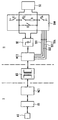
- FIG. 1 is a block diagram of one Device for contactless transmission of signals between circuits on the steering wheel side I and circuits shown on the steering column side II of a vehicle.
- a DÜ rotary transducer For contactless transmission in both directions between Steering wheel side I and steering column side II provide e.g. a DÜ rotary transducer.
- release means AS for an airbag On the steering wheel side I there are release means AS for an airbag.
- the functionality of an airbag is to constantly check so he is in any emergency situation is immediately ready for use. That means it must be recognizable whether the triggering device (squib) of the airbag is in one error-free state. Are the trigger faulty, this must immediately the driver in the vehicle be signaled. Whether the triggering agents are faulty or not, can be determined by measuring their resistance become. If there are no errors, the triggering means have one certain resistance, typically in the range of 1.8 up to 2.5 ohms. If the release means are defective, then whose resistance deviates from the specified value either high-resistance or low-resistance.
- Faults can also consist in that the trigger means a short to Positive pole or to the negative pole of a supply voltage source exhibit.
- One connected to the release means AS Diagnostic device DS measures the resistance of the triggering means AS and forwards the diagnosed resistance value to one first microcontroller MC1 on the steering wheel side I continue.
- the diagnostic device DS evaluates the measured Resistance value to determine if the trigger means are in a faultless condition or one of the have mentioned error states.
- the diagnostic result passes the first microcontroller MC1 as a protocol over the Rotary transformer DÜ to a second microcontroller MC2 the steering column side II.
- a control unit SG On the lens column side II there is a control unit SG, in the event of a vehicle crash, a trigger signal for the Release means AS of the airbag.
- This control unit SG is connected upstream of a simulation circuit SIM serves the current resistance of the trigger means AS replicate.
- the SIM simulation circuit is designed that they both have the correct resistance in the faultless case the trigger means as well as those in each Reproduce the resistance values that occur in fault situations can.
- the simulation circuit contains a resistor R, the resistance of the release means in the faultless case corresponds.
- the resistor R is connected in parallel to the inputs of the control unit SG. In series and parallel to that Resistor R are several electrically controllable switches (e.g. transistors) S1, S2, S3, S4.
- a switch S2 In series with Resistor R is a switch S2 and in parallel with it a switch S3. A switch S1 is also provided, the resistor R with the positive pole U + one Can connect supply voltage and it's a switch S4 available, the resistor with the negative pole U- Short circuit supply voltage.
- the control unit SG In the event of a crash of the vehicle causing the airbag to deploy requires, the control unit SG emits a trigger signal that via the simulation circuit SIM to one Threshold value decision SE arrives. Does that exceed Output signal of the control unit SG an im Threshold value decision SE predefined threshold, so this recognized as a trigger signal and the second Microcontroller MC2 supplied. This transfers it Trigger signal via the rotary transmitter DÜ to the first Microcontroller MC1 on the steering wheel side I. The first Microcontroller MC1 then sends the trigger signal to the Release means AS continue to ignite the airbag.
Landscapes
- Engineering & Computer Science (AREA)
- Mechanical Engineering (AREA)
- Air Bags (AREA)
- Insertion Pins And Rivets (AREA)
- Steering Controls (AREA)
- Dowels (AREA)
Applications Claiming Priority (2)
| Application Number | Priority Date | Filing Date | Title |
|---|---|---|---|
| DE19744760A DE19744760C1 (de) | 1997-10-10 | 1997-10-10 | Vorrichtung zum kontaktfreien Übertragen von Signalen zwischen Lenkrad und Lenksäule |
| DE19744760 | 1997-10-10 |
Publications (3)
| Publication Number | Publication Date |
|---|---|
| EP0908355A2 true EP0908355A2 (fr) | 1999-04-14 |
| EP0908355A3 EP0908355A3 (fr) | 2000-09-06 |
| EP0908355B1 EP0908355B1 (fr) | 2003-07-02 |
Family
ID=7845143
Family Applications (1)
| Application Number | Title | Priority Date | Filing Date |
|---|---|---|---|
| EP98118806A Expired - Lifetime EP0908355B1 (fr) | 1997-10-10 | 1998-10-05 | Dispositif pour la transmission de signaux sans contacts électriques entre volant et colonne de direction |
Country Status (3)
| Country | Link |
|---|---|
| US (1) | US6113140A (fr) |
| EP (1) | EP0908355B1 (fr) |
| DE (2) | DE19744760C1 (fr) |
Families Citing this family (3)
| Publication number | Priority date | Publication date | Assignee | Title |
|---|---|---|---|---|
| US6265294B1 (en) * | 1999-08-12 | 2001-07-24 | Advanced Micro Devices, Inc. | Integrated circuit having double bottom anti-reflective coating layer |
| DE10102994A1 (de) * | 2001-01-24 | 2002-08-01 | Bosch Gmbh Robert | Vorrichtung zur Daten- und/oder Energieübertragung zu Rückhaltemitteln in einem Fahrzeug |
| DE102007044345A1 (de) * | 2007-09-17 | 2009-03-19 | Robert Bosch Gmbh | Schaltung und Verfahren zum Prüfen von elektrisch steuerbaren Leistungsschaltern für ein Ansteuern von Personenschutzmitteln |
Family Cites Families (16)
| Publication number | Priority date | Publication date | Assignee | Title |
|---|---|---|---|---|
| DE3812633A1 (de) * | 1988-04-15 | 1989-10-26 | Daimler Benz Ag | Verfahren zur kontaktlosen widerstandsmessung |
| JPH02158445A (ja) * | 1988-12-09 | 1990-06-18 | Mitsubishi Electric Corp | エアバッグ装置の故障検出装置 |
| US4987316A (en) * | 1989-10-03 | 1991-01-22 | Automotive Systems Laboratory, Inc. | Passenger restraint firing circuit |
| KR930011422B1 (ko) * | 1989-12-20 | 1993-12-06 | 미쯔비시 덴끼 가부시기가이샤 | 고장 검출장치 |
| US5187465A (en) * | 1990-09-27 | 1993-02-16 | Trw Inc. | Method and apparatus for testing a dual airbag passive restraint system |
| US5293153A (en) * | 1991-04-09 | 1994-03-08 | Trw, Inc. | Method and apparatus for testing an airbag restraint system with parallel sensors |
| JP2889725B2 (ja) * | 1991-04-19 | 1999-05-10 | 株式会社デンソー | 車両用エアバッグ装置 |
| JPH04362443A (ja) * | 1991-06-10 | 1992-12-15 | Mitsubishi Electric Corp | 乗員保護装置 |
| US5459449A (en) * | 1994-03-10 | 1995-10-17 | Delco Electronics Corporation | Method and apparatus for diagnosing shorts in a SIR system |
| US5636863A (en) * | 1994-04-26 | 1997-06-10 | Eaton Corporation | Vehicle steering column control system |
| US5612623A (en) * | 1994-05-27 | 1997-03-18 | Nippondenso Co., Ltd. | Failure diagnostic apparatus and method for a resistor element |
| JP3505789B2 (ja) * | 1994-06-03 | 2004-03-15 | 株式会社デンソー | 乗員保護装置用故障診断回路およびその診断方法 |
| DE19530588A1 (de) * | 1995-08-19 | 1997-02-20 | Bosch Gmbh Robert | Anordnung zum Kontrollieren des Widerstandes einer an einem Übertrager angeschlossenen Last |
| DE19530587A1 (de) * | 1995-08-19 | 1997-02-20 | Bosch Gmbh Robert | Anordnung zum Überprüfen des Widerstandes einer an einem Übertrager angeschlossenen Last |
| DE19539070C2 (de) * | 1995-10-20 | 2003-12-18 | Bosch Gmbh Robert | Anordnung zum Ansteuern einer Auslösevorrichtung eines Rückhaltesystems |
| US5936313A (en) * | 1997-08-06 | 1999-08-10 | Siemens Automotive Corp. | Switched capacitor circuit for firing vehicle airbag squibs |
-
1997
- 1997-10-10 DE DE19744760A patent/DE19744760C1/de not_active Expired - Fee Related
-
1998
- 1998-10-05 DE DE59808882T patent/DE59808882D1/de not_active Expired - Lifetime
- 1998-10-05 EP EP98118806A patent/EP0908355B1/fr not_active Expired - Lifetime
- 1998-10-09 US US09/169,556 patent/US6113140A/en not_active Expired - Fee Related
Also Published As
| Publication number | Publication date |
|---|---|
| EP0908355A3 (fr) | 2000-09-06 |
| EP0908355B1 (fr) | 2003-07-02 |
| US6113140A (en) | 2000-09-05 |
| DE59808882D1 (de) | 2003-08-07 |
| DE19744760C1 (de) | 1999-03-18 |
Similar Documents
| Publication | Publication Date | Title |
|---|---|---|
| EP2877866B1 (fr) | Agencement de circuit servant à détecter un type d'électrovanne | |
| DE102004035784B4 (de) | Vorrichtung zur Erfassung einer physikalischen Größe unter Verwendung eines kapazitiven Sensors, Airbagsystem hiermit, sowie Verfahren zum Testen der Vorrichtung | |
| DE4240447C1 (de) | Elektronische Kennung und Erkennung einer fahrzeugspezifischen Kombination optionaler elektronischer Steuergeräte | |
| DE4138096C2 (de) | Fehlererfassungseinrichtung für eine Automobilfahrgast-Schutzeinrichtung | |
| DE102019132242B4 (de) | Verwendungen einer Schaltungsanordnung mit aktiver Messspannung zur Bestimmung eines Isolationswiderstands in einem oder mehreren ungeerdeten Stromversorgungssystem(en) | |
| WO2014009207A1 (fr) | Dispositif de diagnostic d'une circuiterie | |
| EP2181029B1 (fr) | Dispositif de contrôle destiné au contrôle d'une connexion d'un composant de connexion | |
| DE19520373B4 (de) | Fehlerdiagnosevorrichtung für eine Fahrgastschutzvorrichtung | |
| EP1112504A1 (fr) | Circuit de diagnostic pour la mesure de la resistance et du courant de fuite d'au moins un dispositif consommateur electrique, en particulier d'une amorce d'un systeme de protection des passagers d'un vehicule, et systeme de protection equipe dudit circuit | |
| DE10002537A1 (de) | Verfahren zur Detektion einer fehlerhaften Masseverbindung in einer elektrischen Einrichtung insbesondere eines Kraftfahrzeugs | |
| EP0775332B1 (fr) | Ensemble commutateur de securite | |
| DE19815391B4 (de) | Diagnosevorrichtung für Fahrgastschutzsysteme | |
| EP4335033A1 (fr) | Ensemble circuit diagnostiquable, appareil capteur doté d'un ensemble circuit et procédé de diagnostic d'un ensemble circuit et/ou appareil capteur | |
| DE102005016127A1 (de) | Sensorsystem | |
| EP0908355B1 (fr) | Dispositif pour la transmission de signaux sans contacts électriques entre volant et colonne de direction | |
| DE2213977C3 (de) | Schaltung zur Prüfung mehrerer zwischen zwei Klemmen parallel zueinander geschalteter Schaltelemente | |
| EP1972026A1 (fr) | Système d antennes, système de contrôle d accès pour un véhicule automobile et procédé de diagnostic | |
| EP0417392B1 (fr) | Circuit de sortie d'un potentiomètre | |
| DE102008018642B4 (de) | Überwachungsschaltung und Verfahren zum Prüfen der Schaltung | |
| DE19508841A1 (de) | Sicherheitsschalteranordnung | |
| EP0694451B1 (fr) | Dispositif de sécurité pour véhicule | |
| DE102021111734A1 (de) | Diagnosefähige Schaltungsanordnung und Verfahren zur Diagnose einer Schaltungsanordnung | |
| DE10246107B4 (de) | Verfahren sowie Schaltungsanordnung zur Fehlerüberwachung wenigstens eines elektrischen Verbrauchers | |
| EP3997466B1 (fr) | Dispositif de mesure du courant et de la tension d'un signal d'entrée | |
| DE10027184B4 (de) | Anordnung und Verfahren zur Aufprallerkennung in einem Fahrzeug |
Legal Events
| Date | Code | Title | Description |
|---|---|---|---|
| PUAI | Public reference made under article 153(3) epc to a published international application that has entered the european phase |
Free format text: ORIGINAL CODE: 0009012 |
|
| AK | Designated contracting states |
Kind code of ref document: A2 Designated state(s): DE FR GB SE |
|
| AX | Request for extension of the european patent |
Free format text: AL;LT;LV;MK;RO;SI |
|
| PUAL | Search report despatched |
Free format text: ORIGINAL CODE: 0009013 |
|
| AK | Designated contracting states |
Kind code of ref document: A3 Designated state(s): AT BE CH CY DE DK ES FI FR GB GR IE IT LI LU MC NL PT SE |
|
| AX | Request for extension of the european patent |
Free format text: AL;LT;LV;MK;RO;SI |
|
| K1C1 | Correction of patent application (title page) published |
Effective date: 19990414 |
|
| K1C3 | Correction of patent application (complete document) published |
Effective date: 20000906 |
|
| 17P | Request for examination filed |
Effective date: 20010306 |
|
| AKX | Designation fees paid |
Free format text: DE FR GB SE |
|
| GRAH | Despatch of communication of intention to grant a patent |
Free format text: ORIGINAL CODE: EPIDOS IGRA |
|
| GRAH | Despatch of communication of intention to grant a patent |
Free format text: ORIGINAL CODE: EPIDOS IGRA |
|
| GRAA | (expected) grant |
Free format text: ORIGINAL CODE: 0009210 |
|
| AK | Designated contracting states |
Designated state(s): DE FR GB SE |
|
| REG | Reference to a national code |
Ref country code: GB Ref legal event code: FG4D Free format text: NOT ENGLISH |
|
| REF | Corresponds to: |
Ref document number: 59808882 Country of ref document: DE Date of ref document: 20030807 Kind code of ref document: P |
|
| REG | Reference to a national code |
Ref country code: SE Ref legal event code: TRGR |
|
| GBT | Gb: translation of ep patent filed (gb section 77(6)(a)/1977) |
Effective date: 20031029 |
|
| ET | Fr: translation filed | ||
| PLBE | No opposition filed within time limit |
Free format text: ORIGINAL CODE: 0009261 |
|
| STAA | Information on the status of an ep patent application or granted ep patent |
Free format text: STATUS: NO OPPOSITION FILED WITHIN TIME LIMIT |
|
| 26N | No opposition filed |
Effective date: 20040405 |
|
| PGFP | Annual fee paid to national office [announced via postgrant information from national office to epo] |
Ref country code: SE Payment date: 20041025 Year of fee payment: 7 |
|
| PGFP | Annual fee paid to national office [announced via postgrant information from national office to epo] |
Ref country code: GB Payment date: 20050923 Year of fee payment: 8 |
|
| PG25 | Lapsed in a contracting state [announced via postgrant information from national office to epo] |
Ref country code: SE Free format text: LAPSE BECAUSE OF NON-PAYMENT OF DUE FEES Effective date: 20051006 |
|
| PGFP | Annual fee paid to national office [announced via postgrant information from national office to epo] |
Ref country code: FR Payment date: 20051019 Year of fee payment: 8 |
|
| EUG | Se: european patent has lapsed | ||
| GBPC | Gb: european patent ceased through non-payment of renewal fee |
Effective date: 20061005 |
|
| REG | Reference to a national code |
Ref country code: FR Ref legal event code: ST Effective date: 20070629 |
|
| PG25 | Lapsed in a contracting state [announced via postgrant information from national office to epo] |
Ref country code: GB Free format text: LAPSE BECAUSE OF NON-PAYMENT OF DUE FEES Effective date: 20061005 |
|
| PG25 | Lapsed in a contracting state [announced via postgrant information from national office to epo] |
Ref country code: FR Free format text: LAPSE BECAUSE OF NON-PAYMENT OF DUE FEES Effective date: 20061031 |
|
| PGFP | Annual fee paid to national office [announced via postgrant information from national office to epo] |
Ref country code: DE Payment date: 20091215 Year of fee payment: 12 |
|
| REG | Reference to a national code |
Ref country code: DE Ref legal event code: R119 Ref document number: 59808882 Country of ref document: DE Effective date: 20110502 |
|
| PG25 | Lapsed in a contracting state [announced via postgrant information from national office to epo] |
Ref country code: DE Free format text: LAPSE BECAUSE OF NON-PAYMENT OF DUE FEES Effective date: 20110502 |