EP0908551A1 - Fer à repasser à vapeur avec sortie de vapeur sur le devant et le cÔté du fer - Google Patents
Fer à repasser à vapeur avec sortie de vapeur sur le devant et le cÔté du fer Download PDFInfo
- Publication number
- EP0908551A1 EP0908551A1 EP97115418A EP97115418A EP0908551A1 EP 0908551 A1 EP0908551 A1 EP 0908551A1 EP 97115418 A EP97115418 A EP 97115418A EP 97115418 A EP97115418 A EP 97115418A EP 0908551 A1 EP0908551 A1 EP 0908551A1
- Authority
- EP
- European Patent Office
- Prior art keywords
- steam
- soleplate
- ironing
- iron
- steam outlet
- Prior art date
- Legal status (The legal status is an assumption and is not a legal conclusion. Google has not performed a legal analysis and makes no representation as to the accuracy of the status listed.)
- Granted
Links
- XEEYBQQBJWHFJM-UHFFFAOYSA-N Iron Chemical compound [Fe] XEEYBQQBJWHFJM-UHFFFAOYSA-N 0.000 title claims abstract description 360
- 229910052742 iron Inorganic materials 0.000 title claims abstract description 180
- 238000010409 ironing Methods 0.000 claims description 151
- 239000000463 material Substances 0.000 claims description 61
- XLYOFNOQVPJJNP-UHFFFAOYSA-N water Substances O XLYOFNOQVPJJNP-UHFFFAOYSA-N 0.000 claims description 24
- 238000010438 heat treatment Methods 0.000 claims description 18
- 238000001035 drying Methods 0.000 claims description 8
- 230000001154 acute effect Effects 0.000 claims description 5
- 238000009826 distribution Methods 0.000 description 14
- 235000000396 iron Nutrition 0.000 description 6
- XAGFODPZIPBFFR-UHFFFAOYSA-N aluminium Chemical compound [Al] XAGFODPZIPBFFR-UHFFFAOYSA-N 0.000 description 5
- 229910052782 aluminium Inorganic materials 0.000 description 5
- 230000008901 benefit Effects 0.000 description 5
- 230000000694 effects Effects 0.000 description 5
- 239000004744 fabric Substances 0.000 description 5
- 238000009833 condensation Methods 0.000 description 4
- 230000005494 condensation Effects 0.000 description 4
- 238000009499 grossing Methods 0.000 description 4
- 238000001704 evaporation Methods 0.000 description 3
- 230000008020 evaporation Effects 0.000 description 3
- 239000007921 spray Substances 0.000 description 3
- 238000010025 steaming Methods 0.000 description 3
- 238000004519 manufacturing process Methods 0.000 description 2
- 230000007246 mechanism Effects 0.000 description 2
- 230000007480 spreading Effects 0.000 description 2
- 238000003892 spreading Methods 0.000 description 2
- 238000007740 vapor deposition Methods 0.000 description 2
- 238000009834 vaporization Methods 0.000 description 2
- 230000008016 vaporization Effects 0.000 description 2
- 230000037303 wrinkles Effects 0.000 description 2
- 235000008733 Citrus aurantifolia Nutrition 0.000 description 1
- 206010010774 Constipation Diseases 0.000 description 1
- 235000011941 Tilia x europaea Nutrition 0.000 description 1
- 239000011324 bead Substances 0.000 description 1
- 238000005452 bending Methods 0.000 description 1
- 230000015572 biosynthetic process Effects 0.000 description 1
- 239000002131 composite material Substances 0.000 description 1
- 238000000151 deposition Methods 0.000 description 1
- 230000005611 electricity Effects 0.000 description 1
- 230000002349 favourable effect Effects 0.000 description 1
- 230000006872 improvement Effects 0.000 description 1
- 239000004571 lime Substances 0.000 description 1
- 239000002245 particle Substances 0.000 description 1
- 230000002093 peripheral effect Effects 0.000 description 1
- 230000008092 positive effect Effects 0.000 description 1
- 239000002244 precipitate Substances 0.000 description 1
- 238000003825 pressing Methods 0.000 description 1
- 238000005086 pumping Methods 0.000 description 1
- 230000005855 radiation Effects 0.000 description 1
- 230000009467 reduction Effects 0.000 description 1
- 230000000630 rising effect Effects 0.000 description 1
- 229910001220 stainless steel Inorganic materials 0.000 description 1
- 239000010935 stainless steel Substances 0.000 description 1
- 230000028838 turning behavior Effects 0.000 description 1
- 238000004804 winding Methods 0.000 description 1
Images





Classifications
-
- D—TEXTILES; PAPER
- D06—TREATMENT OF TEXTILES OR THE LIKE; LAUNDERING; FLEXIBLE MATERIALS NOT OTHERWISE PROVIDED FOR
- D06F—LAUNDERING, DRYING, IRONING, PRESSING OR FOLDING TEXTILE ARTICLES
- D06F75/00—Hand irons
- D06F75/08—Hand irons internally heated by electricity
- D06F75/10—Hand irons internally heated by electricity with means for supplying steam to the article being ironed
- D06F75/20—Arrangements for discharging the steam to the article being ironed
Definitions
- the present invention relates to a steam iron with a water tank for Supply of an evaporator chamber with water, the in the evaporator chamber supplied water can be converted into steam, and with at least a first and a second steam outlet opening can be connected, a heating element for heating of both the evaporator chamber and an iron soleplate, the Iron sole has an ironing surface and at its front end in the direction of movement has a bow tip and the first steam outlet opening is adjacent to the Bow tip is arranged so that the steam in the area next to the bow tip spreads.
- a steam iron is known from SU 1201376 A, which has a hose line is supplied with steam from an external steam generator and with one second line of electricity to the heating element for heating to the soleplate fed becomes.
- the external steam generation source is usually a Generated vapor pressure of about 200 kilo-pascals, which corresponds to a vapor pressure that is about 1000 times greater than a steam pressure in conventional household irons with integrated water tank and drip valve.
- the soleplate of this Steam iron has a gutter that is substantially parallel to the outer contour the soleplate and immediately adjacent to it on all sides of the iron runs, so that the steam to the front in front of the temple tip, to the back to the The tip of the bow faces away from and exits on both sides.
- the steam is over the Steam pipe passed into a feed channel, the direction of flow of which is almost perpendicular to the ironing material opens into the circumferential channel.
- a much more compact steam iron for normal household use is known from DE-OS 4133295 A1.
- a water tank in the iron is integrated, and a heating element heats both the soleplate and the iron a first and a second evaporator chamber.
- a drip valve Water from the water tank into the first evaporator chamber evenly fed so that the vapor is essentially due to atmospheric pressure and gravitational force a steam pressure of approximately 100 to 200 Pascals from steam outlet openings below of the steam iron emerges.
- a piston pump can also be operated via an operating button operated, which sucks water from the water tank and into the second Evaporator chamber injects so that this vapor due to the pump pressure slightly higher pressure from an opening about 1.3 cm above the ironing surface and arranged adjacent to the temple tip, exits.
- This generated with a piston pump Surface steam impact is commonly referred to as a "jet function”.
- this "jet function" for smoothing particularly difficult to access areas is very suitable, especially when the soleplate is lifted off relative to the items to be ironed, however, a permanent surface steam function is only possible by constant pumping is. Furthermore, only an area around the tip of the iron is vaporized, the Vapor does not spread near the surface due to turbulence.
- a steam iron of the type mentioned at the outset is already known from US Pat. No. 3,722,117 known that a heating element for heating both the soleplate and one Has evaporator chamber, and is provided with a drip valve to gradually Feed water from the water tank integrated in the iron into the evaporator chamber.
- the evaporator chamber can be actuated by either the second steam outlet opening for steam under the iron or with the first steam outlet connected for surface steam. According to this known embodiment, accordingly only one of the two steam functions surface steam or steam under the Irons can be selected.
- Another disadvantage of this embodiment is in that the steam due to the valve mechanism in the steam line very narrow, winding path to the first steam outlet, so that the steam spreads only in an area immediately in front of the temple tip.
- the steam from the first steam outlet opening hits tissue that is only a few centimeters in front of the iron tip and already through heat radiation starting from the soleplate is preheated, so that the condensation properties the steam on the ironing goods are not optimal.
- This effect will reinforced by a quick ironing movement with further reduced steam spreading.
- the narrow steam path and the valve mechanism to the first steam outlet opening susceptible to constipation due to gradually depositing lime particles.
- the first steam outlet opening Similar to DE-OS 4133295 above the soleplate and only at the tip of the iron arranged so that a lot of escaping steam is also on the housing of the Iron itself precipitates and a not a small proportion of the total steam the first steam outlet is useless as a high cloud of steam in front of the iron hovers, and condenses in the air, with the additional risk of scalding the Hands of the operator is raised.
- the first and the second steam outlet opening are advantageously in the soleplate of the iron trained so that the steam spreads very close to the surface because today's iron soles usually have a height of less than 10 mm and so that the second steam outlet opening arranged in the soleplate for the Surface steam to less than 10 mm above the height relative to the ironing material or Ironing surface of the soleplate preferably at a height of less than 5 mm emerges in the ironing position relative to the ironing surface.
- Another impact of the arrangement The first and second steam outlet opening in the soleplate is that the The soleplate of the iron is automatically sufficiently hot so that there are no condensation drops can form at the outlet opening without additional parts attached would have to be in thermal contact with the sole.
- first and second steam outlet openings are connected in a pressure-equalizing manner, so that in the event that one of the two steam vents or groups is closed by steam outlet openings by thick fabric to be ironed or at least the applied steam pressure is reduced, via the other steam outlet opening self-regulating more steam escapes.
- the first and the second steam outlet opening are advantageously independent of the ironing material in connection.
- This is the pressure-equalizing connecting line or connecting groove between the first and second steam outlet opening dimensioned or designed such that even with very soft fabric of the ironing material and thereby deeply pressing the steam iron into the ironing material a pressure-equalizing steam connection between the first and second steam outlet openings given is.
- the steam connection is pressure equalizing, that preferably no valve is interposed.
- the second steam outlet opening arranged within the substantially flat ironing surface, so that by the second steam outlet opens the steam under the steam iron and the ironing material is moistened under the steam iron. It is therefore constantly on simultaneous operation of conventional steam under the steam iron and Surface steam through the first steam outlet next to the steam iron possible, so that a significant improvement in the smoothing result after just one time Ironing is given.
- the ironing material is caused by the surface steam preconditioned from the first steam outlet opening very close to the surface and then conventionally smoothed by ironing.
- first steam outlet opening and / or the second steam outlet opening in uninterrupted connection to the evaporator chamber.
- the nominal steam flow rates can thus be achieved under all actual ironing conditions to be kept.
- the first steam outlet opening is located via a groove on the ironing surface in connection with the second steam outlet opening, the groove opening into the first steam outlet opening.
- a groove in the Iron sole has the advantage that in one embodiment the groove is only the Extension of the steam outlet opening already arranged in a groove-like depression for steam below the steam iron.
- Another just here The embodiment shown provides that the pressure-equalizing connection between the first and second steam outlet opening and / or the connection to Evaporator chamber not in the ironing surface of the iron soleplate but in the one above it Body which receives the heating element is formed. By this measure is absolutely ensured that this steam connection is not interrupted by the ironing material can be.
- This solution is especially heavy for ironing soles deformable materials such as Stainless steel or relevant for iron soles that a flat ironing surface with no or as few depressions or interruptions as possible provide the ironing surface or the flatness of the ironing surface.
- an imaginary center line closes first and second steam outlet opening through the groove with an imaginary line of symmetry through the temple tip and the middle of the temple surface at an acute angle, so that the steam emerging from the first steam outlet opening in the direction of movement is directed sideways in front.
- the course of the groove defines the direction of the Steam outlet for an area around the temple tip or around the front half of the Iron around tight.
- the opposite edge of the soleplate forms the groove between the Steam outlet openings preferably in the form of a V or W.
- second steam outlet openings are provided, which are essentially V-shaped the tip of the V are arranged facing the iron tip, so that the iron can be easily moved or rotated.
- the first steam outlet opening is formed by a bevel on the edge of the ironing surface.
- the bevel preferably has only an angle between 2 ° and 10 ° relative to the material to be ironed, so that the steam emerging from the first steam outlet opening is very close to the surface is directed.
- the flatness of the beveled surface has a rounded shape also the advantage that a defined, small exit angle of the steam from the first steam outlet opening with little or no undesirable steam direction components up to the operator is reached.
- the bevel only extends so close to the tip of the iron that the flat iron surface of the soleplate up to Extending the temple tip and around the temple tip, the first steam outlet opening is arranged adjacent to this area. This leaves one Fine temple tip despite the adjacent bevel on the two adjacent sides of the soleplate edge preserved, the unchanged for particularly difficult to access Areas, e.g. around buttons, is usable. Because the bevel, however Extending close to the temple tip ensures that a surface steam in there is a larger area in front of the temple tip.
- first steam outlet opening above the ironing surface and on the side of the Iron soleplate is designed, on the one hand, is a very flat steam outlet for very Near-surface steam is possible, on the other hand, the steam outlet opening is through the Iron sole itself formed so no condensation drops around the first one Lower the steam outlet opening, with the risk of "closing" the first Steam outlet opening hardly exists.
- one of which is fixed to the steam iron connected iron soleplate removable and attachable further iron soleplate provided, in which either only first steam outlet openings are formed, so that a conventional steam iron by putting on the additional soleplate can only be switched to surface steam or additional surface steam. If there are only steam outlet openings for surface steam, there is pressure equalization particularly advantageous if one of the steam outlet openings through a Bead in the ironing material prevents the steam from escaping, so that the nominal Vapor flow rates can be maintained.
- the first or the first steam outlet openings are) starting from the temple tip on both sides at an edge area of the Iron sole trained and extends only so far to the middle or to rear part relative to the preferred direction of the temple tip, so that the front part of the steam iron humidification or steaming of the iron takes place and an exclusive over the rear part of the steam iron The ironing material is dried.
- the iron soles shown in the figures are part of a household iron, which essentially has the following structure.
- the steam iron is provided with a housing on which a handle and different buttons for the temperature selection, for the steam quantity selection, for the Water spray and, depending on the equipment, various other (steam) functions that can be operated are trained.
- the steam iron for example, has a "shot-of-steam” function with which a powerful burst of steam between the soleplate and Ironing goods are handed over.
- the steam iron is e.g. B. with a so-called “Jet” function equipped which gives a powerful burst of steam far into front of the iron tip allows.
- the steam iron has a water tank integrated or integrable in the housing on, which is intended as a reservoir for the steam to be produced.
- the steam iron also has a so-called shoe 13 (cf. FIG. 12c) the underside of which is attached to the soleplate 1, 2, 3, 4, 5, 6, 7, 8, 9, 10, 11, 12.
- the shoe 13 is designed as a cast aluminum body, in which a heating resistor 14 as Heating element is embedded.
- the heating resistor 14 corresponds to the shape of the Arrangement of the second steam outlet openings 15, arranged in a U-shape in the shoe 13.
- the shoe 13 preferably has an evaporator chamber, which consists of a steam generating camera and a steam distribution chamber which is always in steam connection with this 16 exists.
- the steam generating chamber is in a central area of the shoe 13 on the inside relative to the heating resistor 14, and is upwards to the side facing away from the soleplate from a steam chamber cover 17 sealed.
- the steam distribution chamber 16 is open towards the bottom of the iron. Starting from the steam distribution chamber 16 that in the steam generation chamber generated steam, depending on the embodiment, to those in steam connection with it first and / or second steam outlet openings 18, 15 out.
- the soleplate 1, 2, 3, 4, 5, 6, 7, 8, 9, 10, 11, 12 is made of aluminum sheet formed and at the edge area - as shown in Fig. 12c - bent so that a acute angle is included and the edge region of the shoe 13 is edged.
- the first steam outlet opening 18 is formed in the soleplate of the iron.
- a continuously flat soleplate is used (not shown in the figures), in which the edge area The first steam outlet opening is also flat without bending above the soleplate and can be formed on it, due to the thin material thickness such an iron sole of about 2-3 mm is still sufficiently close to the surface Escape of the steam is possible.
- the first steam outlet opening 18 there is an opening for the outlet of steam understood the soleplate 1, 2, 3, 4, 5, 6, 7, 8, 9, 10, 11, 12 or the shoe 13, which is arranged on the outer peripheral edge of the soleplate or the shoe and as a result, the hot steam from the evaporator chamber does not get under the Soleplate, but next to this leads to the outlet.
- This vapor is called Surface steam, which is on the surface of the ironing material at the not of the Ironsole spreads out covered areas.
- second steam outlet opening 15 there is an opening for the outlet of steam understood the soleplate 1, 2, 3, 4, 5, 6, 7, 8, 9, 10, 11, 12 or the shoe 13, which releases the hot steam under the soleplate, but in the area leaves out, which is covered by the iron when ironing the ironing material.
- the second Steam outlet similar to the first one for the formation of surface steam arranged.
- the second Steam outlet opening not the special case, but the normal case described above designated.
- a plurality of first and second steam outlet openings is preferred in each case 18, 15 provided.
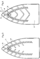
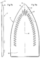
- FIGS. 1-8, 9a, 10a, 11a and 12a show a plan view of the side of the soleplate, which faces the ironing during ironing.
- the second steam outlet openings 15 are similar in FIGS. 1-8 and 9a-12a to each other and in the soleplate 1, 2, 3, 4, 5, 6, 7, 8, 9, 10, 11, 12 arranged.
- the second steam outlet is exemplary for all these figures 15 described below with reference to FIG. 12a.
- the second steam outlet openings 15 conventional and independent are formed by the first steam outlet openings 18.
- There are a total 71 individual second steam outlet openings 15 are provided, which together in essentially U or V-shaped directly below the uniformly shaped steam distribution chamber 16 are arranged.
- the U or V shape of all second steam outlet openings corresponds to the outer contour of the soleplate 12, so that the tip of the V is arranged adjacent to the temple tip.
- the second steam outlet 15 are bores through the soleplate 12 and to the steam distribution chamber 16 educated. There are always two or more second steam outlet openings 15 in one connecting groove summarized, viewed from above (see Fig. 12) drop-shaped trained and aligned towards the front of the temple tip or towards the side towards the front are.
- first steam outlet openings 18 formed for surface steam in that the teardrop-shaped groove of second steam outlet openings to the side or outer contour of the soleplate are extended so that through the mouth of such a groove 19, 24, 25, 26th the first for surface steam on the outer contour together with the ironing material Steam outlet opening is formed.
- Through the groove 19, 24, 25, 26 are thus the first and the second steam outlet opening 18, 15 connected to one another in a pressure-equalizing manner.
- the first and second steam outlet openings are with the Steam distribution chamber 16 in constant steam connection and thus with this pressure equalizing or connected in pressure balance.
- Vapor pressure continues to be sufficient to pass through the first vents 18 to steam the ironing material.
- the pressure equalizing connection ensures that Evaporation takes place under all ironing conditions. It is usually used at Steam iron of this type with drip valve and instant evaporation of the in the Steam generating chamber got water droplets by atmospheric pressure and Gravitational force a vapor pressure of maximum 200 Pa or a vapor release rate of achieved less than 16 g / min. A higher vapor pressure is disadvantageous because the air emitted and rising steam increases significantly. It is therefore important that the iron soles with the household iron of the entrance mentioned type is combined.
- the iron soleplate 1 In the iron soleplate 1 according to FIG. 1 there are a total of 5 grooves 19, each approximately one V-shaped course provided.
- the "tip" of the V is rounded to (rounded) ironing tip 20 of the soleplate is oriented in the opposite direction and cuts the imaginary connecting line between temple tip 20 and the rear side the soleplate 1.
- This connecting line also forms an axis of symmetry around the the steam outlet openings 18, 15 are arranged mirror-symmetrically.
- the steam outlet openings 18 from the grooves 19 are seen in the direction of movement in a front region of the sides 22 and 23 adjoining the temple tip 20 arranged.
- the second steam outlet openings 18 extend approximately to front half relative to the front temple tip 20.
- the two legs of the V-shaped grooves 19 enclose an angle of about 60-110 °, so that of steam coming into these grooves for surface steam a flow direction and Has exit direction in the direction of movement laterally at the front. In this respect it is from Meaning, since it is assumed that when ironing always in an area around the Always iron the ironing tip first or to the side next to the ironing tip first is so that these areas are preconditioned with surface vapor before they be ironed over by the soleplate 1.
- This offset of the first steam outlet opening 18 relative to the temple tip 20 in the rear in the direction of movement on the one hand ensures that the area immediately in front of the temple tip 20 is also vaporized with surface steam and, on the other hand, the temple tip 20 can be used without the material being ironed can get caught in a first steam outlet opening 18.
- the Iron soles 1, 2 and 3 are for the V-shaped closest to the tip of the iron Groove 19 an additional second steam outlet opening 15 to provide steam provided under the iron and surface steam.
- the iron soles 1, 3 and 4 follows the V-shaped groove 19 just described, another V-shaped one Groove, the "tip" of which is very rounded.
- Grooves 19 Between these two foremost V-shaped ones Grooves 19 are three teardrop-shaped grooves with second steam outlet openings 15 arranged.
- At the soleplate 1 are in the second V-shaped groove seen from the bracket tip 20 additionally in the tip area of the V further second steam outlet openings 15 - in total nine of them - arranged so that in a front area of the soleplate A lot of surface steam is provided around the temple tip 20.
- the Iron soleplate 1 follows the further V-shaped grooves on every second drop-shaped Groove for second steam outlet openings 15 to a total in this embodiment five V-shaped grooves 19 are provided.
- the iron soleplate 3 according to FIG. 3 differs from the iron soleplate 2 in essentially only in that two front V-shaped grooves 19 are provided the three grooves 25 follow to the side facing away from the temple tip 20, which are not only towards the outer contour 22, 23 of the soleplate 3 an extension of the drop-shaped Grooves of the second steam outlet openings 15, but also in the inner Area towards the above-mentioned imaginary symmetry or connecting line 50 Have extension, but without two opposite each other at the same height Grooves 25 are brought together in the middle to form a V.
- This sole represents the mode of operation is a compromise between the soleplate 2 and 4.
- the soleplate 4 is designed such that one facing away from the tip of the iron Larger post-drying area 26 adjacent to the rear outer contour edge 21 the soleplate 4 is provided. Furthermore, it points directly to the bow tip 20 adjacent V-shaped groove 19 two second steam outlet openings 15, so that more surface steam is also available in the area immediately around the tip stands.
- the soleplate 5 according to FIG. 5 has one that is directly adjacent to the tip 20 of the iron first V-shaped groove 19 which, through three second steam outlet openings 15 Steam, among other things, for surface steam from the first steam outlet openings provided. Finally, the drop-shaped ones follow to the side facing away from the bow tip 20 Groove only outwardly extending grooves 24, as already for the soleplate 2 executed. Finally, every fourth teardrop-shaped groove with second steam outlet openings follows 15 still a total of three W-shaped grooves 26.
- the W-shaped Grooves 26 represent a steam flow direction similar to the grooves 19, 24 and 25 for surface steam outside the soleplate, to the side at the front around the temple tip and in a front area around the at the temple tip adjacent pages 22 and 23 ready.
- the connecting grooves 27 are similar to that W-shaped grooves 26 formed on the soleplate 5 such that between two opposite teardrop-shaped grooves for second steam outlet openings 15 the Connection groove has approximately the shape of a V, the rounded "tip" to the temple tip 20 indicates.
- the Connecting groove 27 does not extend the groove outward to the outer contour provided for the release of surface steam.
- the connecting grooves thus serve 27 for increased moistening of the ironing material below the soleplate when ironing, with the same advantages as the soleplate 5 a there is good rotatability of the soleplate on the material to be ironed.
- the iron soleplate 7 according to FIG. 7 is similar to all of the iron soleplates described above two steam outlet openings 15, which have the overall shape of a V or U with the tip of the V or the curve of the U facing the bow tip 20. It three foremost teardrop-shaped grooves are provided, in which the second steam outlet openings 15 each triple for each teardrop groove in the tip area are drilled in. Subsequently, in the direction facing away from the bow tip 20, there are two Opposing teardrop-shaped grooves, each with three holes for second steam outlet openings connected to a common approximately V-shaped groove and provided with a total of nine second steam outlet openings 15. The summit This V-shaped groove is for steam only under the steam iron Bow tip 20 facing away, so arranged in mirror image to this.
- the soleplate 7 is characterized in a special way by that the entire central area and a large rear area facing away from the temple tip 20 and facing the rear outer edge 21 as a large post-drying zone is provided without any steam outlet opening.
- this soleplate 7 Over the length of the Iron sole 7 from the tip of the iron 20 to the rear outer edge 21, adjacent to which the iron can also be switched off, this soleplate 7 has a vapor deposition area for steam under the iron and for surface steam on the essentially only on the front half, that is to say facing the bow tip 20 Half located.
- the sides 22 directly adjacent to the temple tip 20, 23 of the outer contour of the soleplate 7 have a face toward the tip 20 area tapering to one another.
- the first and second steam vents are essentially only in this "tapered" area of the soleplate 7 arranged.
- To provide surface steam are on the soleplate 7 a V-shaped groove 19 immediately adjacent to the bracket tip 20 similar to the V-shaped grooves on the previous iron soles, and on both sides five short grooves or recesses 28 are provided.
- the V-shaped groove 19 is with three second steam outlet openings 15 supplied with steam, so that one particularly large amount of steam through the first steam outlet openings 18 of the V-shaped groove 19 emerges directly into an area around the bow tip 20.
- the short grooves 28 extend on both sides of the sides 22 and 23 adjoining the temple tip starting from the outer contour inwards (by about 1 cm) to the middle of the ironing surface, and are similar to the previously described grooves 19, 24, 25, 26 at such an angle arranged to the outer contour 22, 23 of the sides adjacent to the temple tip 20 that a steam direction component to the front of the temple tip or a steam direction is provided laterally at the front. It is intended to ensure that only the area is provided with surface steam in the direction of movement for the first time Ironing over an area closest to the item to be ironed.
- the direction in which the iron moves is regarded as the direction of movement is that immediately in front of the temple tip 20 or immediately on the neighboring Areas of the soleplate adjacent to the tip of the iron and in front of these areas.
- the surface steam is in this area to the side of the soleplate by the arrangement of the first steam outlet openings 18 and Alignment of the grooves 19, 24, 25, 26, 28 is evaporated onto the material to be ironed.
- the iron can be moved in all directions, it should be the one described above
- Direction of movement should be the preferred way of ironing, usually with the items being ironed for the first time becomes.
- the short grooves 28 are after the foremost three teardrop-shaped grooves for the second steam outlet opening 15 with the subsequent third drop-shaped Grooves aligned.
- the short grooves 28 are at their inner end region with a second steam outlet opening 29, the one hand steam under the iron and on the other hand surface steam along the short groove 28 and through the first steam outlet 18 provides.
- the second steam outlet opening 29 is preferably located as well as the second steam outlet opening 15 with the teardrop-shaped grooves with the Steam distribution chamber 16 in connection.
- the soleplate 8 is similar to the soleplate 4 with V-shaped grooves 19 provided, the closest to the bracket tip 20 V-shaped groove 19 with three and the subsequent V-shaped groove with nine second steam outlet openings is. As with the previous grooves for surface steam are also at In this embodiment, the V-shaped grooves are approximately the same relative to one another Distance from each other and arranged on a front area relative to the temple tip. The first V-shaped groove 19 immediately adjacent to the bracket tip 20 closes between her legs an angle of about 60 ° or a half angle 30 of 30 °.
- This angle between the legs of the V-shaped groove 19 increases slightly from groove 19 to groove 19 in the direction of movement to the rear, so that the angle 31st between the longitudinal central axis 50 of the soleplate and the central axis 49 through the Groove 19 of a leg of the V-shaped groove encloses an angle of greater than 50 °.
- a representative cut through one of the grooves 19 along the longitudinal axis or axis of symmetry 50 of the soleplate 8 shows (see FIG. 8a) the manner in which the groove is pressed into the aluminum sheet part is trained.
- the width of the groove 33 is preferably 2-4 mm in a lower area in the area that rests on the material to be ironed (reference symbol 34 in FIG. 8) 3-5 mm.
- the surface steam passes through a bevel 38 on the outer contour of the soleplate.
- this bevel is formed as a flat surface in itself which every point on this surface is essentially the same acute angle to the rest plan iron surface 39 of the iron sole 9, 10, 11 includes.
- a rounded outer contour for surface steam can be created with the bevel a flat surface vapor spread at an acute included angle to the material to be ironed Ensure that there is no major loss of steam upwards into the air.
- Bevels 38 is a very even and flat vapor spread for surface steam possible.
- FIG. 9a two embodiments are in the iron soleplate 9 shown at the same time shown.
- the left bevel with circular to each other spaced first steam outlet openings 18 and the right bevel with a plurality of slot-shaped, spaced-apart first steam outlet openings 18 is provided, the opposite bevel in mirror image should be the same first steam outlet openings 18, so that only in the bevels circular openings or only slots are formed.
- the bow tip 20 and the but directly adjacent bracket surface 39 is not with a bevel provided, but formed flat, so that the area around the temple tip unchanged can be used as a fine ironing tip for hard-to-reach areas on the ironing material.
- the Bevel 38 is on the sides immediately adjacent to the temple tip near the Arranged outer contour and extends to about the middle or 2/3 of the soleplate length starting from the temple tip 20.
- a side view of the soleplate 9 - extends the bevel 38 starting from the ironing surface 39 in the upward direction towards Bow handle, by about 1-4 mm, preferably 1-2 mm, (see dimension 40 in Fig. 9b).
- the second Steam outlet openings 15 are conventional without a drop-shaped grooves Groove connection to the first steam outlet opening arranged in the soleplate 9. Both steam outlet openings are, for example, via the steam distribution chamber 16 inside the shoe 13 to equalize pressure, i.e. via the same steam supply path, continuously connected.
- FIG. 10a shows an embodiment similar to the embodiments in FIG. 9a. Different features are therefore only described for this embodiment.
- the soleplate 10 has no openings in the bevel and is instead provided with extending grooves 41, which are similar to the soleplate 2 a steam connection between the first and second steam outlet opening 18, 15 effect.
- the extending groove 41 extends the teardrop-shaped groove for the second steam outlet openings 15 to the outside to the outer contour of the soleplate down to the bevel, so that the steam over the bevel as surface steam escapes.
- the first steam outlet opening 18 is between the items to be ironed and the intermediate gap formed by the bevel along the two to the Temple tip formed adjacent sides.
- the bevel 38 has one Width of about 4-6 mm.
- the bevels 38 are in all embodiments however, generally dimensioned such that the first steam outlet opening 18 is independent the quality of the ironing material at any time with the second steam outlet 15 is connected to equalize pressure.
- FIG. 11 a shows an iron soleplate 11 in which the second steam outlet openings 15 are arranged in a conventional manner, as previously described.
- the first Vapor outlet opening 18 is through a gap between the bevel 43 and the Ironing material formed.
- the bevel 43 extends as far as the middle area the soleplate 11 that at least the foremost three relative to the tip 20 drop-shaped grooves for the second steam outlet opening 15 partially in the bevel reach in so that a steam connection between the first and second Steam outlet opening is formed.
- the bevel 43 forms a with the ironing first steam outlet opening 18, which is in contrast to all other exemplary embodiments extends into an area including the temple tip 20.
- the soleplate 11 is thereby formed with a beveled fine temple tip, which for taken like other aspects of this application, the subject of a patent application can be.
- the bevel 43 extends from the temple tip towards the opposite side from 1/5 to 1/3 of the total length of the tip of the iron to the back of the soleplate.
- This is a fine ironing tip integrated with which by holding the iron slightly inclined only in the front area can be ironed around the temple tip without the one behind Areas come into contact with the remaining ironing surface 39 and thus unwanted wrinkles could be ironed in while using the beveled Fine ironing tips are difficult to reach areas of the ironing material.
- the ironing tip In normal operation of the iron, in which the ironing surface 39 is in contact with the ironing material, however, the ironing tip is due to the bevel 43 from the ironing material raised, so that the surface steam is particularly intense and efficient in one foremost area spreads around the temple tip 20.
- the bevel 43 extends along the axis of symmetry 50 a few centimeters to the ironing surface 39.
- Fig. 11b is a side view of the soleplate 11 without other components of the Iron shown.
- the flat bevel 43 of the fine ironing tip, taken on its own is at an angle to the imaginary extension of the remaining flat ironing surface 39, 44 inclined by 3-6 °. This tendency is sufficient to ensure constant pressure equalization Connection between first and second steam outlet opening independent to ensure of the ironing material.
- the relatively small angle 44 gives a steam flow direction before that a very near surface spread of surface vapor enables.
- FIG. 12a shows, as already described at the beginning, an iron soleplate 12 in which in are conventionally arranged second steam outlet openings.
- steam outlet openings 18 are only shown in FIG. 12b shown side view of the soleplate recognizable, since they are spaced apart side slits or other, e.g. B. circular openings in the bent Sidewall of the soleplate are formed.
- This embodiment ensures a conventional constant ironing surface, as in previous ones Iron is also the case, with the peculiarity that surface steam is still through the first steam outlet openings 18 can emerge laterally along the outer contour.
- the first steam outlet openings 18 are, starting from the temple tip 20, in the front third of the soleplate 12, with no slot opening being formed in the area directly at the temple tip should be to avoid getting caught with the ironing material. Nevertheless, by the The first steam outlet opening 18 closest to the bow tip ensures that the surface steam at the present steam pressure also up to just before Bow tip 20 spreads.
- Fig. 12c - a partial section through the shoe and the soleplate - is the pressure-equalizing connection between the first and given second steam outlet opening in that 13 grooves, channels or Slots or the like are formed so that the first steam outlet openings 18th are in steam connection with the steam distribution chamber 16.
- FIG. 13 shows a perspective top view illustration of an iron shoe 46 can be placed on a conventional steam iron. So it is possible to go through Place the iron shoe 46 on the iron sole firmly attached to the steam iron to provide an iron that additionally has first steam vents for surface steam.
- the iron shoe 46 points immediately below the second steam outlet opening 15 of the steam iron (in composite Condition with the soleplate 46) of the second steam openings 47.
- the second Steam openings 47 are approximately rectangular or V-shaped in the tip area, so that the steam underneath the iron remains undiminished to the items to be ironed is forwarded.
- Through channels 48 there is a steam connection from the second steam outlet openings to the first steam outlet openings.
- the channels 48 are aligned similar to the grooves 24 of the soleplate 2, but can also be arranged on the side facing away from the ironing surface of the soleplate 46, so that the first steam outlet openings 18 when the steam iron is on the soleplate 46 similar to that in FIG. 12b at a height of a few millimeters be formed above the ironing surface.
- FIG. 14 symbolically shows an iron soleplate 47, which is one of the ones described above Corresponds to iron soles.
- the schematically illustrated soleplate 47 has one Bow tip 20, immediately adjacent sides 22 and 23 and one to the bow tip opposite side 21 of the outer contour.
- 14 serves to illustrate the Steam spreading of the surface steam, which is in an area around the temple tip, in front of and next to it, as well as in a front area of the adjacent pages 22 and 23 is provided.
- the steam cloud for surface steam does not extend quite as far as in FIG. 14 shown, so only about 1/4 starting from the temple tip to the rear.
- the first steam outlet opening in a front area, starting from the temple tip, extends 1/5 to 2/3 of the total length to the rear or at least in the rear area of the soleplate, which is the surface of the iron facing a drying zone over at least 1/7 to half of the Total length of the soleplate is designed so that not only for good moistening or steaming the ironing material, but also for sufficient Drying is taken care of.
Landscapes
- Engineering & Computer Science (AREA)
- Textile Engineering (AREA)
- Irons (AREA)
Priority Applications (6)
| Application Number | Priority Date | Filing Date | Title |
|---|---|---|---|
| DE59702213T DE59702213D1 (de) | 1997-09-05 | 1997-09-05 | Dampfbügeleisen mit Dampfaustritt vor bzw. neben dem Bügeleisen |
| EP97115418A EP0908551B1 (fr) | 1997-09-05 | 1997-09-05 | Fer à repasser à vapeur avec sortie de vapeur sur le devant et le côté du fer |
| ES97115418T ES2151214T3 (es) | 1997-09-05 | 1997-09-05 | Plancha de vapor con salida de vapor en la parte delantera y lateral. |
| PT97115418T PT908551E (pt) | 1997-09-05 | 1997-09-05 | Ferro de engomar a vapr com saida de vapr a frente ou dos lados do ferrode engomar |
| US09/148,841 US6216369B1 (en) | 1997-09-05 | 1998-09-04 | Steam iron with steam discharge ahead of and along the side of the iron |
| HK99104538.3A HK1021391B (en) | 1999-10-14 | Steam iron with steam output at the front and sides of the iron sole |
Applications Claiming Priority (1)
| Application Number | Priority Date | Filing Date | Title |
|---|---|---|---|
| EP97115418A EP0908551B1 (fr) | 1997-09-05 | 1997-09-05 | Fer à repasser à vapeur avec sortie de vapeur sur le devant et le côté du fer |
Publications (2)
| Publication Number | Publication Date |
|---|---|
| EP0908551A1 true EP0908551A1 (fr) | 1999-04-14 |
| EP0908551B1 EP0908551B1 (fr) | 2000-08-16 |
Family
ID=8227320
Family Applications (1)
| Application Number | Title | Priority Date | Filing Date |
|---|---|---|---|
| EP97115418A Expired - Lifetime EP0908551B1 (fr) | 1997-09-05 | 1997-09-05 | Fer à repasser à vapeur avec sortie de vapeur sur le devant et le côté du fer |
Country Status (5)
| Country | Link |
|---|---|
| US (1) | US6216369B1 (fr) |
| EP (1) | EP0908551B1 (fr) |
| DE (1) | DE59702213D1 (fr) |
| ES (1) | ES2151214T3 (fr) |
| PT (1) | PT908551E (fr) |
Cited By (7)
| Publication number | Priority date | Publication date | Assignee | Title |
|---|---|---|---|---|
| WO2002018698A1 (fr) * | 2000-08-30 | 2002-03-07 | Jean Delbaere | Fer a repasser a evacuation de vapeur |
| DE102005062641A1 (de) * | 2005-12-23 | 2007-07-05 | Braun Gmbh | Bügeleisen |
| US7516566B2 (en) | 2003-12-16 | 2009-04-14 | Koninklijke Philips Electronics N.V. | Steam iron having a lightweight soleplate and flat resistive heating tracks for heating the soleplate |
| EP2603630A2 (fr) * | 2010-08-12 | 2013-06-19 | Koninklijke Philips Electronics N.V. | Fer à repasser présentant une humidification de vêtement grâce à une phase liquide |
| EP2703552A1 (fr) * | 2012-08-30 | 2014-03-05 | BSH Bosch und Siemens Hausgeräte GmbH | Dispositif de repassage à vapeur |
| FR3001234A1 (fr) * | 2013-01-22 | 2014-07-25 | Seb Sa | Appareil de repassage a la vapeur comportant un generateur de vapeur et un fer a repasser |
| FR3001233A1 (fr) * | 2013-01-22 | 2014-07-25 | Seb Sa | Appareil de repassage a la vapeur comportant un generateur de vapeur et un fer a repasser |
Families Citing this family (19)
| Publication number | Priority date | Publication date | Assignee | Title |
|---|---|---|---|---|
| BRPI0500228A (pt) * | 2004-01-30 | 2005-09-20 | Celaya Emparanza Galdos Int Sa | Aperfeiçoamentos para ferros a vapor domésticos possuindo uma câmara de vaporização e encaixada com elemento de calor independente |
| US7188442B2 (en) * | 2004-04-26 | 2007-03-13 | Products Of Tomorrow, Inc. | Ironing device |
| US20050278988A1 (en) * | 2004-04-26 | 2005-12-22 | Products Of Tomorrow, Inc. | Ironing device |
| CN1664222B (zh) * | 2004-12-20 | 2010-05-05 | 松下·万宝(广州)电熨斗有限公司 | 电熨斗 |
| US7178276B2 (en) * | 2004-12-20 | 2007-02-20 | Matsushita Electric Industrial Co., Ltd. | Steam iron |
| JP4277795B2 (ja) * | 2004-12-20 | 2009-06-10 | パナソニック株式会社 | スチームアイロン |
| ES2278539B1 (es) * | 2006-01-31 | 2008-07-16 | Celaya, Emparanza Y Galdos, Internacional, S.A. | Suela de plancha y plancha que la contiene. |
| USD630399S1 (en) * | 2008-11-05 | 2011-01-04 | Rowenta Werke Gmbh | Soleplate for laundry iron |
| FR2952385B1 (fr) * | 2009-11-12 | 2012-01-20 | Seb Sa | Fer a repasser comportant une semelle presentant un evidement muni de trous de sortie de vapeur |
| AU331547S (en) * | 2009-12-01 | 2010-06-30 | Calor Sa | Soleplate for laundry iron |
| GB2485553B (en) * | 2010-11-17 | 2014-01-22 | Richards Morphy N I Ltd | Electric iron with nozzle for water mist |
| JP2014509916A (ja) | 2011-04-04 | 2014-04-24 | コーニンクレッカ フィリップス エヌ ヴェ | 蒸気アイロン |
| US8776409B2 (en) * | 2011-04-20 | 2014-07-15 | Notable Creations, Inc. | Apparatus for removing wrinkles from fabric |
| WO2015106054A1 (fr) | 2014-01-09 | 2015-07-16 | Herrild Natalie | Dispositif de repassage |
| WO2016011161A1 (fr) * | 2014-07-15 | 2016-01-21 | Sunbeam Products, Inc. | Fer à repasser avec canaux de vapeur et semelle texturée |
| CA159445S (en) | 2014-09-26 | 2015-06-09 | Richards Morphy N I Ltd | Iron |
| USD804129S1 (en) * | 2016-10-12 | 2017-11-28 | Sunbeam Products, Inc. | Iron soleplate |
| FR3115297B1 (fr) * | 2020-10-16 | 2023-04-07 | Seb Sa | Appareil de defroissage portatif comportant une surface de traitement en textile |
| CN219010759U (zh) * | 2022-11-28 | 2023-05-12 | 张莉 | 一种蒸汽电熨斗 |
Citations (5)
| Publication number | Priority date | Publication date | Assignee | Title |
|---|---|---|---|---|
| US1674092A (en) * | 1926-03-12 | 1928-06-19 | Cannon Engineering Co | Sadiron |
| US3407521A (en) * | 1966-06-09 | 1968-10-29 | Westinghouse Electric Corp | Steam iron |
| US3722117A (en) * | 1972-05-15 | 1973-03-27 | Gen Electric | Steam nozzle iron |
| US3738033A (en) * | 1972-09-18 | 1973-06-12 | Gen Electric | Steam flatiron |
| DE4133295A1 (de) * | 1991-10-08 | 1993-04-15 | Braun Ag | Dampfbuegeleisen |
Family Cites Families (7)
| Publication number | Priority date | Publication date | Assignee | Title |
|---|---|---|---|---|
| US2729004A (en) * | 1953-04-22 | 1956-01-03 | Swanson Carl Arthur | Laundry iron |
| US2846793A (en) * | 1955-04-21 | 1958-08-12 | Hoover Co | Smoothing iron soleplate |
| SU1201376A1 (ru) * | 1983-09-12 | 1985-12-30 | Yunusov Damir A | Утюг |
| DE3603409A1 (de) * | 1985-06-05 | 1986-12-11 | Rowenta-Werke Gmbh, 6050 Offenbach | Elektrisch beheiztes dampfbuegeleisen |
| US4642922A (en) * | 1985-12-06 | 1987-02-17 | D.M.D.S.R.L. | Removable steam iron sole plate |
| FR2662188B1 (fr) * | 1990-05-18 | 1992-09-04 | Seb Sa | Fer a repasser a semelle recouverte par un revetement reduisant le frottement. |
| EP0676498A3 (fr) * | 1994-04-06 | 1996-04-17 | Braun Ag | Sortie et distribution de vapeur. |
-
1997
- 1997-09-05 EP EP97115418A patent/EP0908551B1/fr not_active Expired - Lifetime
- 1997-09-05 DE DE59702213T patent/DE59702213D1/de not_active Expired - Lifetime
- 1997-09-05 ES ES97115418T patent/ES2151214T3/es not_active Expired - Lifetime
- 1997-09-05 PT PT97115418T patent/PT908551E/pt unknown
-
1998
- 1998-09-04 US US09/148,841 patent/US6216369B1/en not_active Expired - Lifetime
Patent Citations (5)
| Publication number | Priority date | Publication date | Assignee | Title |
|---|---|---|---|---|
| US1674092A (en) * | 1926-03-12 | 1928-06-19 | Cannon Engineering Co | Sadiron |
| US3407521A (en) * | 1966-06-09 | 1968-10-29 | Westinghouse Electric Corp | Steam iron |
| US3722117A (en) * | 1972-05-15 | 1973-03-27 | Gen Electric | Steam nozzle iron |
| US3738033A (en) * | 1972-09-18 | 1973-06-12 | Gen Electric | Steam flatiron |
| DE4133295A1 (de) * | 1991-10-08 | 1993-04-15 | Braun Ag | Dampfbuegeleisen |
Cited By (8)
| Publication number | Priority date | Publication date | Assignee | Title |
|---|---|---|---|---|
| WO2002018698A1 (fr) * | 2000-08-30 | 2002-03-07 | Jean Delbaere | Fer a repasser a evacuation de vapeur |
| US7516566B2 (en) | 2003-12-16 | 2009-04-14 | Koninklijke Philips Electronics N.V. | Steam iron having a lightweight soleplate and flat resistive heating tracks for heating the soleplate |
| DE102005062641A1 (de) * | 2005-12-23 | 2007-07-05 | Braun Gmbh | Bügeleisen |
| EP2603630A2 (fr) * | 2010-08-12 | 2013-06-19 | Koninklijke Philips Electronics N.V. | Fer à repasser présentant une humidification de vêtement grâce à une phase liquide |
| EP2703552A1 (fr) * | 2012-08-30 | 2014-03-05 | BSH Bosch und Siemens Hausgeräte GmbH | Dispositif de repassage à vapeur |
| FR3001234A1 (fr) * | 2013-01-22 | 2014-07-25 | Seb Sa | Appareil de repassage a la vapeur comportant un generateur de vapeur et un fer a repasser |
| FR3001233A1 (fr) * | 2013-01-22 | 2014-07-25 | Seb Sa | Appareil de repassage a la vapeur comportant un generateur de vapeur et un fer a repasser |
| EP2757190A3 (fr) * | 2013-01-22 | 2017-11-08 | Seb S.A. | Appareil de repassage à la vapeur comportant un générateur de vapeur et un fer a repasser |
Also Published As
| Publication number | Publication date |
|---|---|
| PT908551E (pt) | 2000-11-30 |
| HK1021391A1 (en) | 2000-06-09 |
| EP0908551B1 (fr) | 2000-08-16 |
| US6216369B1 (en) | 2001-04-17 |
| DE59702213D1 (de) | 2000-09-21 |
| ES2151214T3 (es) | 2000-12-16 |
Similar Documents
| Publication | Publication Date | Title |
|---|---|---|
| EP0908551B1 (fr) | Fer à repasser à vapeur avec sortie de vapeur sur le devant et le côté du fer | |
| EP0923656B1 (fr) | Fer a repasser electrique a semelle | |
| DE3014656C2 (de) | Verfahren zur Verstärkung von Oberstoffen für Kleidungsstücke und Vorrichtung hierfür | |
| DE69216561T2 (de) | Elektrisches Dampfbügeleisen | |
| DE1954880A1 (de) | Gasabgabeduese | |
| DE2035081C3 (de) | Vorrichtung zum kontinuierlichen Auftragen eines Glätte- oder Verfestigungsmittels auf einen laufenden Textilfaden | |
| DE4431252B4 (de) | Verfahren und Vorrichtung zum Bedrucken einer Materialbahn | |
| DE19800954A1 (de) | Vorrichtung zum direkten oder indirekten Auftragen eines flüssigen oder pastösen Auftragsmediums auf eine laufende Materialbahn, insbesondere aus Papier oder Karton | |
| DE2938244A1 (de) | Verfahren zur kontrolle des feuchtigkeitsgehalts einer faserbahn und vorrichtung zur durchfuehrung des verfahrens und papierherstellungsmaschine zur durchfuehrung des verfahrens und papierherstellungsmaschine mit einer vorrichtung zur durchfuehrung des verfahrens | |
| DE3435051C2 (de) | Dampfbügeleisen | |
| DE4437375C2 (de) | Vorrichtung und Verfahren zum Befeuchten einer vorbeilaufenden Materialbahn | |
| DE102005062641A1 (de) | Bügeleisen | |
| DE1561640A1 (de) | Verfahren und Vorrichtung zur Belueftung einer Trockenzylinderpartie | |
| DE4430548A1 (de) | Dampfbügeleisen | |
| DE10116840A1 (de) | Verfahren und Vorrichtung zum Glätten einer Materialbahn | |
| EP1724389B1 (fr) | Dispositif de repassage à vapeur avec générateur de vapeur fixe relié à un fer à repasser | |
| DE476394C (de) | Buegeleisen mit einem Verdampfungsraum und einem Luftheizraum | |
| DE202013102761U1 (de) | Vorrichtung zur Oberflächenleimung einer Faserbahn | |
| DE2132844C3 (de) | Trockenvorrichtung für eine Webmaschine | |
| DE202005007735U1 (de) | Dampfbügeleisen | |
| DE2340802A1 (de) | Dampfbuegeleisen | |
| WO2010130548A1 (fr) | Dispositif de repassage | |
| EP0377803A1 (fr) | Fer à repasser à vapeur électrique | |
| DE2820914B2 (de) | Verfahren und Vorrichtung zum Nachbehandeln von laufenden Textilbahnen | |
| DE1511183A1 (de) | Einstellvorrichtung fuer den Ausfluss eines gasfoermigen Mediums |
Legal Events
| Date | Code | Title | Description |
|---|---|---|---|
| PUAI | Public reference made under article 153(3) epc to a published international application that has entered the european phase |
Free format text: ORIGINAL CODE: 0009012 |
|
| 17P | Request for examination filed |
Effective date: 19970905 |
|
| AK | Designated contracting states |
Kind code of ref document: A1 Designated state(s): BE CH DE ES FI FR GB IT LI NL PT |
|
| RAP1 | Party data changed (applicant data changed or rights of an application transferred) |
Owner name: BRAUN GMBH |
|
| AKX | Designation fees paid | ||
| RBV | Designated contracting states (corrected) |
Designated state(s): BE CH DE ES FI FR GB IT LI NL PT |
|
| GRAG | Despatch of communication of intention to grant |
Free format text: ORIGINAL CODE: EPIDOS AGRA |
|
| GRAG | Despatch of communication of intention to grant |
Free format text: ORIGINAL CODE: EPIDOS AGRA |
|
| GRAH | Despatch of communication of intention to grant a patent |
Free format text: ORIGINAL CODE: EPIDOS IGRA |
|
| GRAH | Despatch of communication of intention to grant a patent |
Free format text: ORIGINAL CODE: EPIDOS IGRA |
|
| GRAA | (expected) grant |
Free format text: ORIGINAL CODE: 0009210 |
|
| ITF | It: translation for a ep patent filed | ||
| AK | Designated contracting states |
Kind code of ref document: B1 Designated state(s): BE CH DE ES FI FR GB IT LI NL PT |
|
| RIN1 | Information on inventor provided before grant (corrected) |
Inventor name: GILI, SERGI Inventor name: POZO-MARIN, REMEDIOS Inventor name: VAZQUEZ-PALMA, MIGUEL Inventor name: WOLF, JUERGEN Inventor name: CORONADO, JUAN CARLOS Inventor name: MARTINEZ, CANDELARIO Inventor name: FALCO, DESIDERI Inventor name: REBORDOSA, ANTONIO |
|
| REG | Reference to a national code |
Ref country code: CH Ref legal event code: NV Representative=s name: LUCHS & PARTNER PATENTANWAELTE Ref country code: CH Ref legal event code: EP |
|
| GBT | Gb: translation of ep patent filed (gb section 77(6)(a)/1977) |
Effective date: 20000816 |
|
| REF | Corresponds to: |
Ref document number: 59702213 Country of ref document: DE Date of ref document: 20000921 |
|
| ET | Fr: translation filed | ||
| REG | Reference to a national code |
Ref country code: PT Ref legal event code: SC4A Free format text: AVAILABILITY OF NATIONAL TRANSLATION Effective date: 20000830 |
|
| REG | Reference to a national code |
Ref country code: ES Ref legal event code: FG2A Ref document number: 2151214 Country of ref document: ES Kind code of ref document: T3 |
|
| PLBE | No opposition filed within time limit |
Free format text: ORIGINAL CODE: 0009261 |
|
| STAA | Information on the status of an ep patent application or granted ep patent |
Free format text: STATUS: NO OPPOSITION FILED WITHIN TIME LIMIT |
|
| 26N | No opposition filed | ||
| REG | Reference to a national code |
Ref country code: GB Ref legal event code: IF02 |
|
| PGFP | Annual fee paid to national office [announced via postgrant information from national office to epo] |
Ref country code: PT Payment date: 20030822 Year of fee payment: 7 |
|
| PGFP | Annual fee paid to national office [announced via postgrant information from national office to epo] |
Ref country code: FI Payment date: 20030922 Year of fee payment: 7 Ref country code: BE Payment date: 20030922 Year of fee payment: 7 |
|
| PGFP | Annual fee paid to national office [announced via postgrant information from national office to epo] |
Ref country code: NL Payment date: 20030923 Year of fee payment: 7 |
|
| PGFP | Annual fee paid to national office [announced via postgrant information from national office to epo] |
Ref country code: CH Payment date: 20030925 Year of fee payment: 7 |
|
| PG25 | Lapsed in a contracting state [announced via postgrant information from national office to epo] |
Ref country code: FI Free format text: LAPSE BECAUSE OF NON-PAYMENT OF DUE FEES Effective date: 20040905 |
|
| PG25 | Lapsed in a contracting state [announced via postgrant information from national office to epo] |
Ref country code: LI Free format text: LAPSE BECAUSE OF NON-PAYMENT OF DUE FEES Effective date: 20040930 Ref country code: CH Free format text: LAPSE BECAUSE OF NON-PAYMENT OF DUE FEES Effective date: 20040930 Ref country code: BE Free format text: LAPSE BECAUSE OF NON-PAYMENT OF DUE FEES Effective date: 20040930 |
|
| PG25 | Lapsed in a contracting state [announced via postgrant information from national office to epo] |
Ref country code: PT Free format text: LAPSE BECAUSE OF NON-PAYMENT OF DUE FEES Effective date: 20050307 |
|
| BERE | Be: lapsed |
Owner name: *BRAUN G.M.B.H. Effective date: 20040930 |
|
| PG25 | Lapsed in a contracting state [announced via postgrant information from national office to epo] |
Ref country code: NL Free format text: LAPSE BECAUSE OF NON-PAYMENT OF DUE FEES Effective date: 20050401 |
|
| REG | Reference to a national code |
Ref country code: CH Ref legal event code: PL |
|
| REG | Reference to a national code |
Ref country code: PT Ref legal event code: MM4A Free format text: LAPSE DUE TO NON-PAYMENT OF FEES Effective date: 20050307 |
|
| NLV4 | Nl: lapsed or anulled due to non-payment of the annual fee |
Effective date: 20050401 |
|
| BERE | Be: lapsed |
Owner name: *BRAUN G.M.B.H. Effective date: 20040930 |
|
| REG | Reference to a national code |
Ref country code: FR Ref legal event code: PLFP Year of fee payment: 20 |
|
| PGFP | Annual fee paid to national office [announced via postgrant information from national office to epo] |
Ref country code: GB Payment date: 20160830 Year of fee payment: 20 Ref country code: IT Payment date: 20160914 Year of fee payment: 20 |
|
| PGFP | Annual fee paid to national office [announced via postgrant information from national office to epo] |
Ref country code: FR Payment date: 20160817 Year of fee payment: 20 |
|
| PGFP | Annual fee paid to national office [announced via postgrant information from national office to epo] |
Ref country code: ES Payment date: 20160830 Year of fee payment: 20 |
|
| PGFP | Annual fee paid to national office [announced via postgrant information from national office to epo] |
Ref country code: DE Payment date: 20160928 Year of fee payment: 20 |
|
| REG | Reference to a national code |
Ref country code: DE Ref legal event code: R071 Ref document number: 59702213 Country of ref document: DE |
|
| REG | Reference to a national code |
Ref country code: GB Ref legal event code: PE20 Expiry date: 20170904 |
|
| PG25 | Lapsed in a contracting state [announced via postgrant information from national office to epo] |
Ref country code: GB Free format text: LAPSE BECAUSE OF EXPIRATION OF PROTECTION Effective date: 20170904 |
|
| REG | Reference to a national code |
Ref country code: ES Ref legal event code: FD2A Effective date: 20180508 |
|
| PG25 | Lapsed in a contracting state [announced via postgrant information from national office to epo] |
Ref country code: ES Free format text: LAPSE BECAUSE OF EXPIRATION OF PROTECTION Effective date: 20170906 |