EP0908654B1 - Electrovanne pour la régulation de débit - Google Patents
Electrovanne pour la régulation de débit Download PDFInfo
- Publication number
- EP0908654B1 EP0908654B1 EP19980117392 EP98117392A EP0908654B1 EP 0908654 B1 EP0908654 B1 EP 0908654B1 EP 19980117392 EP19980117392 EP 19980117392 EP 98117392 A EP98117392 A EP 98117392A EP 0908654 B1 EP0908654 B1 EP 0908654B1
- Authority
- EP
- European Patent Office
- Prior art keywords
- needle
- valve
- orifice
- metering
- core
- Prior art date
- Legal status (The legal status is an assumption and is not a legal conclusion. Google has not performed a legal analysis and makes no representation as to the accuracy of the status listed.)
- Expired - Lifetime
Links
- 229910000831 Steel Inorganic materials 0.000 claims description 8
- 239000010959 steel Substances 0.000 claims description 8
- 238000009966 trimming Methods 0.000 claims description 3
- 230000000284 resting effect Effects 0.000 claims description 2
- 238000004891 communication Methods 0.000 description 3
- 239000012530 fluid Substances 0.000 description 2
- 238000012986 modification Methods 0.000 description 2
- 230000004048 modification Effects 0.000 description 2
- 238000012937 correction Methods 0.000 description 1
- 230000003247 decreasing effect Effects 0.000 description 1
- 238000013461 design Methods 0.000 description 1
- 238000009434 installation Methods 0.000 description 1
- 238000004519 manufacturing process Methods 0.000 description 1
- 238000005259 measurement Methods 0.000 description 1
Images
Classifications
-
- F—MECHANICAL ENGINEERING; LIGHTING; HEATING; WEAPONS; BLASTING
- F16—ENGINEERING ELEMENTS AND UNITS; GENERAL MEASURES FOR PRODUCING AND MAINTAINING EFFECTIVE FUNCTIONING OF MACHINES OR INSTALLATIONS; THERMAL INSULATION IN GENERAL
- F16K—VALVES; TAPS; COCKS; ACTUATING-FLOATS; DEVICES FOR VENTING OR AERATING
- F16K31/00—Actuating devices; Operating means; Releasing devices
- F16K31/02—Actuating devices; Operating means; Releasing devices electric; magnetic
- F16K31/06—Actuating devices; Operating means; Releasing devices electric; magnetic using a magnet, e.g. diaphragm valves, cutting off by means of a liquid
- F16K31/0686—Braking, pressure equilibration, shock absorbing
- F16K31/0693—Pressure equilibration of the armature
-
- Y—GENERAL TAGGING OF NEW TECHNOLOGICAL DEVELOPMENTS; GENERAL TAGGING OF CROSS-SECTIONAL TECHNOLOGIES SPANNING OVER SEVERAL SECTIONS OF THE IPC; TECHNICAL SUBJECTS COVERED BY FORMER USPC CROSS-REFERENCE ART COLLECTIONS [XRACs] AND DIGESTS
- Y10—TECHNICAL SUBJECTS COVERED BY FORMER USPC
- Y10T—TECHNICAL SUBJECTS COVERED BY FORMER US CLASSIFICATION
- Y10T137/00—Fluid handling
- Y10T137/5109—Convertible
- Y10T137/5283—Units interchangeable between alternate locations
Definitions
- This invention relates to an electrical solenoid valve for creating a variable restriction to control the rate of flow of pilot oil under pressure.
- Proportional valves are more complex in their design than standard open-closed type solenoid valves and far more expensive.
- the delivery port is in constant communication through the tubular interior of the valve spool with the opposing end face of the spool remote from the delivery port.
- the other of the valve chamber ports is respectively a pressure supply port and an exhaust port and is located on opposite sides of the valve spool port for selective communication through the spool port and the tubular interior of the valve spool with said delivery port in different positions of the valve spool.
- the valve spool is axially biased by a spring toward the delivery port.
- a tubular solenoid armature is axially loosely connected to the end of the spool remote from the supply port and adapted for actuation to displace the spool axially against the biasing spring.
- a further object of the invention is to reduce manufacturing and stocking costs of two essential types of flow metering valves by providing the options of having the flow path of the solenoid either "open” or “closed” in their position of rest when no electrical power is applied, employing identical parts in the solenoid assembly, with one minor exception.
- a further object of the invention is to achieve interchangeability between a standard open-close two position type solenoid and a variable flow solenoid without the requirement of additional installation space or any other modification to the main hydraulic valve manifold.
- an electrical solenoid valve for creating a variable restriction to control the rate of flow of pilot oil under pressure comprising a tube assembly having a steel housing, a coil within the steel housing, a non magnetic tube surrounded by the steel housing, a magnetizable anchor firmly attached at the upper end of the non magnetic tube and a flange firmly attached at the lower end of the non magnetic tube.
- Said valve comprises further a valve manifold into which the tube assembly is fixed by the flange, a needle guide clamped in place by the valve manifold, and a movable core assembly resting upon the needle guide and having a cylindrical magnetizable core, a flow metering needle fixedly carried below the core, a metering spring above the core for pressing the core downward to the needle guide and causing a gap between an upper face of the core and a lower face of the anchor.
- Said valve includes also an axial center bore passing axially through the center of the needle, an orifice bored radially through the needle, and a metering lip on the internal diameter of the needle guide forming with the orifice a variable restriction.
- the moveable core assembly is in a hydraulically balanced state in that both ends of the needle are subject to a pilot oil pressure of the same magnitude by means of the axial center bore.
- the pilot oil being metered flows through the orifice into the axial center bore and exits the orifice through the variable restriction.
- the needle with its orifice is axially movable through the needle guide to positions directly influenced by the electrical power applied to the coil as the subsequent attracting magnetic force between the core and the anchor balances the resistance of the metering spring to provide a required, rate of flow of the pilot oil in a given direction from a higher to a lower source of the pilot oil pressure through the variable restriction.
- the radially bored needle orifice may be located just below an upper metering lip of the needle guide, so that the valve is in an open position when the coil is de-energized and closes proportionally to the increasing strength of the electrical power applied to the coil.
- the radially bored needle orifice may be located just below a lower metering lip of a flow control seat, so that the valve is in a closed position when the coil is de-energized and opens proportionally to the increasing strength of the electrical power applied to the coil.
- pilot oil is in a reverse direction to the given direction and enters the orifice over the upper metering lip or the lower metering lip and exits through the center bore of the needle.
- a trimming screw can be built into the anchor to adjust the force of the metering spring acting against the magnetizable core to match an available electrical power range metering the rate of oil flow.
- valve is interchangeable with a standard two position open-closed type solenoid without any change to the main valve manifold without requiring additional space external to the manifold.
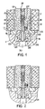
- Fig. 1 illustrates the variable flow solenoid valve of the present invention, of the "open when de-energized" type.
- Fig. 2 illustrates the variable flow solenoid valve of the present invention, of the "closed when de-energized" type.
- the coil housing 11 and electrical coil 12 are standard to the industry.
- the solenoid casing 13 consists of a non-magnet tube 14 welded together with a magnetisable soft steel anchor 15 at the upper end and a threaded flange 16 at the lower end.
- a soft steel core 17 fitting loosely within the tube assembly carries a firmly attached flow metering needle 18 with an axial center bore 19 and a radial orifice 20 or 21 connecting a higher pressure source passage 30 with a lower pressure source passage 31.
- the radial orifice may be situated either at the upper end of the flow metering needle where it is "open" to flow in relation to the upper metering lip 23 as in (Fig. 3a) when the coil is de-energized or it may be at the lower end of the flow metering needle where it is "closed” to flow in relation to the lower metering lip 24 as in (Fig. 3b) when the coil is de-energized.
- the flow metering needle fits closely but freely moveable in the needle guide 22 which is clamped into a recess in the main valve manifold 1 by the solenoid casing. Between metering lips 23 and 24 of the needle guide is a cavity 25 from which leads a radial bore 26 connecting the cavity to a lower pressure source through passage 31.
- the direction of oil flow through the solenoid can be from passage 30 to passage 31 as described or in the reverse direction, depending to which passages the higher and lower pressure sources are attached.
- the core 17 In rest position, the core 17 is pressed downwards against the needle guide 22 by the metering spring 27 creating a gap between the core and the anchor.
- a trimming screw 28 is built into the cylindrical anchor 15 increase or reduce the force of the metering spring 27 acting against the magnetisable core 17 to match the available electrical power range metering the rate of oil flow.
- Fig. 1 illustrates the solenoid arrangement with the needle radial orifice 20 below the “upper” metering lip 23 of the guide assembly and therefore "open” to flow through spring pressure when the coil is de-energized.
Landscapes
- Engineering & Computer Science (AREA)
- General Engineering & Computer Science (AREA)
- Mechanical Engineering (AREA)
- Magnetically Actuated Valves (AREA)
- Steering Control In Accordance With Driving Conditions (AREA)
Claims (6)
- Électrovanne pour créer une limitation variable permettant de réguler le débit d'huile pilote sous pression, comprenantun ensemble tubulaire ayantun boítier en acier (11),une bobine (12) à l'intérieur du boítier en acier (11),un tube amagnétique (14) entouré par le boítier en acier (11),une pièce d'ancrage magnétisable (15) solidement fixée à l'extrémité supérieure du tube amagnétique (14), etune bride filetée (16) solidement fixée à l'extrémité supérieure du tube amagnétique (14) ;une tubulure de vanne (1) dans laquelle l'ensemble tubulaire est vissé par la bride filetée (16),un guide de pointeau (22) bloqué en position par la tubulure de vanne (1),un ensemble de noyau mobile reposant sur le guide de pointeau (22) ayantun noyau cylindrique magnétisable (17),un pointeau de régulation de débit (18) supporté de manière fixe sous le noyau (17),un ressort de régulation (27) au-dessus du noyau (17) pour appuyer le noyau (17) vers le bas sur le guide de pointeau (22) et former un espace entre une face supérieure du noyau (17) et une face inférieure de la pièce d'ancrage (15);un trou central axial (19) traversant axialement le centre du pointeau (18),un orifice (20, 21) percé radialement dans le pointeau (18), etune lèvre de régulation (23, 24) sur le diamètre interne du guide de pointeau (22) formant une limitation variable avec l'orifice (20, 21),dans lequel l'ensemble de noyau mobile est dans un état hydrauliquement équilibré en ce que les deux extrémités du pointeau (18) sont soumises à une pression d'huile pilote de même grandeur au moyen du trou axial central (19),tandis que l'huile pilote régulée s'écoule par l'orifice (20, 21) dans le trou axial central (19) et sort de l'orifice (20, 21) par la limitation variable, etdans lequel le pointeau (18) avec son orifice (20, 21) peut être amené axialement par le guide de pointeau (22) sur des positions directement influencées par la puissance électrique appliquée à la bobine (12) alors que la force magnétique d'attraction résultante entre le noyau (17) et la pièce d'ancrage (15) équilibre la résistance du ressort de régulation (27) pour fournir un débit exigé de l'huile pilote dans une direction donnée d'une source haute pression à basse pression de l'huile pilote par la limitation variable.
- Vanne selon la revendication 1, dans laquelle l'orifice de pointeau percé radialement (20) est situé juste au-dessous d'une lèvre de régulation supérieure (23) du guide de pointeau (22), afin que la vanne soit dans une position ouverte lorsque la bobine (12) est désexcitée et se ferme proportionnellement à la force croissante de la puissance électrique appliquée à la bobine (12).
- Vanne selon la revendication 1, dans laquelle l'orifice de pointeau percé radialement (21) est situé juste au-dessous d'une lèvre de régulation inférieure (24) du guide de pointeau (22), afin que la vanne soit dans une position fermée lorsque la bobine (12) est désexcitée et s'ouvre proportionnellement à la force croissante de la puissance électrique appliquée à la bobine (12).
- Vanne selon l'une quelconque des revendications précédentes, dans laquelle l'huile pilote s'écoule dans une direction inverse à la direction donnée, entre dans l'orifice (20) au-dessus de la lèvre de régulation supérieure (23) ou entre dans l'orifice (21) au-dessus de la lèvre de régulation inférieure (24) et sort par le trou central (19) du pointeau (18).
- Vanne selon l'une quelconque des revendications précédentes, dans laquelle une vis d'ajustage (28) est incorporée dans la pièce d'ancrage (15) pour ajuster la force du ressort de régulation (27) agissant sur le noyau magnétisable (17) pour adapter une plage de puissance électrique disponible régulant le débit d'huile.
- Vanne selon l'une quelconque des revendications précédentes, dans laquelle la vanne est interchangeable avec une électrovanne du type à deux positions ouverte-fermée ne nécessitant aucune modification de la tubulure de vanne principale et aucun espace supplémentaire à l'extérieur de la tubulure.
Applications Claiming Priority (2)
| Application Number | Priority Date | Filing Date | Title |
|---|---|---|---|
| US946477 | 1997-10-07 | ||
| US08/946,477 US6220277B1 (en) | 1997-10-07 | 1997-10-07 | Flow metering solenoid valve |
Publications (3)
| Publication Number | Publication Date |
|---|---|
| EP0908654A2 EP0908654A2 (fr) | 1999-04-14 |
| EP0908654A3 EP0908654A3 (fr) | 1999-10-20 |
| EP0908654B1 true EP0908654B1 (fr) | 2003-03-05 |
Family
ID=25484526
Family Applications (1)
| Application Number | Title | Priority Date | Filing Date |
|---|---|---|---|
| EP19980117392 Expired - Lifetime EP0908654B1 (fr) | 1997-10-07 | 1998-09-14 | Electrovanne pour la régulation de débit |
Country Status (6)
| Country | Link |
|---|---|
| US (1) | US6220277B1 (fr) |
| EP (1) | EP0908654B1 (fr) |
| JP (1) | JP3411508B2 (fr) |
| AT (1) | ATE233876T1 (fr) |
| DE (1) | DE69811815T2 (fr) |
| ES (1) | ES2194262T3 (fr) |
Families Citing this family (3)
| Publication number | Priority date | Publication date | Assignee | Title |
|---|---|---|---|---|
| US6786467B2 (en) * | 2002-01-31 | 2004-09-07 | Siemens Vdo Automotive Inc. | Longer stroke control valve and actuator |
| WO2006056611A1 (fr) * | 2004-11-26 | 2006-06-01 | Continental Teves Ag & Co. Ohg | Appareil de regulation a commande electromagnetique et procede pour le realiser et/ou le regler |
| EP3569904B1 (fr) * | 2018-05-18 | 2020-11-04 | Fas Medic S.A. | Ensemble de soupape |
Family Cites Families (12)
| Publication number | Priority date | Publication date | Assignee | Title |
|---|---|---|---|---|
| CA465736A (fr) * | 1950-06-06 | Clare Sprankling Le Clair Camille | Systeme distributeur de liquide ou lubrifiant | |
| US2893428A (en) | 1956-05-22 | 1959-07-07 | Int Basic Economy Corp | Solenoid operated pressure balanced flow valve |
| DE1054298B (de) * | 1956-05-22 | 1959-04-02 | Internat Basic Economy Corp | Entlasteter Steuerschieber fuer einen einfach wirkenden Servomotor |
| DE2658928A1 (de) * | 1976-12-24 | 1978-07-06 | Beringer Hydraulik Gmbh | Hydraulische steuerung |
| DE2942886C2 (de) | 1979-10-24 | 1983-10-06 | Zahnradfabrik Friedrichshafen Ag, 7990 Friedrichshafen | Elektrohydraulisches Servoventil |
| JPH0724711Y2 (ja) * | 1988-12-27 | 1995-06-05 | 株式会社小松製作所 | 電気式油圧比例制御弁 |
| US5218999A (en) * | 1990-05-17 | 1993-06-15 | Mitsubishi Denki K.K. | Solenoid valve |
| JP3451283B2 (ja) * | 1994-06-17 | 2003-09-29 | Smc株式会社 | バランス形直動電磁弁 |
| US5593004A (en) * | 1995-03-28 | 1997-01-14 | Blain Roy W | Servo control for hydraulic elevator |
| US5607137A (en) | 1995-09-08 | 1997-03-04 | Eaton Corporation | Electrically operated flow control valve |
| DE19547374A1 (de) * | 1995-12-19 | 1997-06-26 | Bosch Gmbh Robert | Elektrisch steuerbares Ventil insbesondere zum Einbau in eine hydraulische Fahrzeugbremsanlage |
| US5853028A (en) * | 1997-04-30 | 1998-12-29 | Eaton Corporation | Variable force solenoid operated valve assembly with dampener |
-
1997
- 1997-10-07 US US08/946,477 patent/US6220277B1/en not_active Expired - Lifetime
-
1998
- 1998-09-14 EP EP19980117392 patent/EP0908654B1/fr not_active Expired - Lifetime
- 1998-09-14 ES ES98117392T patent/ES2194262T3/es not_active Expired - Lifetime
- 1998-09-14 DE DE1998611815 patent/DE69811815T2/de not_active Expired - Lifetime
- 1998-09-14 AT AT98117392T patent/ATE233876T1/de not_active IP Right Cessation
- 1998-09-25 JP JP27147198A patent/JP3411508B2/ja not_active Expired - Fee Related
Also Published As
| Publication number | Publication date |
|---|---|
| EP0908654A3 (fr) | 1999-10-20 |
| JP3411508B2 (ja) | 2003-06-03 |
| US6220277B1 (en) | 2001-04-24 |
| JPH11173452A (ja) | 1999-06-29 |
| DE69811815D1 (de) | 2003-04-10 |
| ATE233876T1 (de) | 2003-03-15 |
| ES2194262T3 (es) | 2003-11-16 |
| EP0908654A2 (fr) | 1999-04-14 |
| DE69811815T2 (de) | 2004-03-04 |
Similar Documents
| Publication | Publication Date | Title |
|---|---|---|
| CA2194116C (fr) | Robinet doseur electromagnetique a force variable | |
| US4966195A (en) | Transmission pressure regulator | |
| US5611370A (en) | Proportional variable force solenoid control valve and transmission fluid control device | |
| US6966329B2 (en) | Proportional pilot-operated flow control valve | |
| US6269827B1 (en) | Electrically operated pressure control valve | |
| US5538026A (en) | Pilot-operated proportional control valve | |
| JP3044563B2 (ja) | 比例流量弁 | |
| US4947893A (en) | Variable force solenoid pressure regulator for electronic transmission controller | |
| US6725877B2 (en) | Solenoid valve for delivering a fluid at a variable flow-rate | |
| US4655249A (en) | Electromagnetic valve | |
| US4725039A (en) | Self-pressure regulating proportional valve | |
| US5114116A (en) | Electromagnetically actuated quick-action switching valve | |
| US6899313B2 (en) | Magnetic actuator and method | |
| CA1229541A (fr) | Regulateur de pression | |
| US5607137A (en) | Electrically operated flow control valve | |
| US4538643A (en) | Electropneumatic pilot control stage for a pneumatic servo valve | |
| US6343621B1 (en) | Variable force solenoid control valve | |
| US6390129B2 (en) | Proportional solenoid-operated fluid metering device | |
| US3937242A (en) | Pressure control device for controlling the flow of a fluid medium | |
| JP2865728B2 (ja) | 比例弁 | |
| US6415820B1 (en) | Variable assist power steering system and flow control valve therefor | |
| GB2186349A (en) | Proportional solenoid valve | |
| US4694270A (en) | Electromagnetic proportional actuator | |
| CA2219030C (fr) | Robinet pressostatique a commande electrique | |
| US4722364A (en) | Electromagnet for fuel injection systems |
Legal Events
| Date | Code | Title | Description |
|---|---|---|---|
| PUAI | Public reference made under article 153(3) epc to a published international application that has entered the european phase |
Free format text: ORIGINAL CODE: 0009012 |
|
| AK | Designated contracting states |
Kind code of ref document: A2 Designated state(s): AT CH DE ES FR GB GR IT LI NL SE |
|
| AX | Request for extension of the european patent |
Free format text: AL;LT;LV;MK;RO;SI |
|
| PUAL | Search report despatched |
Free format text: ORIGINAL CODE: 0009013 |
|
| AK | Designated contracting states |
Kind code of ref document: A3 Designated state(s): AT BE CH CY DE DK ES FI FR GB GR IE IT LI LU MC NL PT SE |
|
| AX | Request for extension of the european patent |
Free format text: AL;LT;LV;MK;RO;SI |
|
| 17P | Request for examination filed |
Effective date: 20000202 |
|
| AKX | Designation fees paid |
Free format text: AT CH DE ES FR GB GR IT LI NL SE |
|
| 17Q | First examination report despatched |
Effective date: 20020226 |
|
| GRAH | Despatch of communication of intention to grant a patent |
Free format text: ORIGINAL CODE: EPIDOS IGRA |
|
| GRAH | Despatch of communication of intention to grant a patent |
Free format text: ORIGINAL CODE: EPIDOS IGRA |
|
| GRAA | (expected) grant |
Free format text: ORIGINAL CODE: 0009210 |
|
| AK | Designated contracting states |
Designated state(s): AT CH DE ES FR GB GR IT LI NL SE |
|
| REG | Reference to a national code |
Ref country code: GB Ref legal event code: FG4D |
|
| REG | Reference to a national code |
Ref country code: CH Ref legal event code: EP |
|
| REG | Reference to a national code |
Ref country code: SE Ref legal event code: TRGR |
|
| REF | Corresponds to: |
Ref document number: 69811815 Country of ref document: DE Date of ref document: 20030410 Kind code of ref document: P |
|
| REG | Reference to a national code |
Ref country code: CH Ref legal event code: NV Representative=s name: M. ZARDI & CO. SA |
|
| REG | Reference to a national code |
Ref country code: GR Ref legal event code: EP Ref document number: 20030402020 Country of ref document: GR |
|
| PG25 | Lapsed in a contracting state [announced via postgrant information from national office to epo] |
Ref country code: AT Free format text: LAPSE BECAUSE OF NON-PAYMENT OF DUE FEES Effective date: 20030914 |
|
| ET | Fr: translation filed | ||
| REG | Reference to a national code |
Ref country code: ES Ref legal event code: FG2A Ref document number: 2194262 Country of ref document: ES Kind code of ref document: T3 |
|
| PLBE | No opposition filed within time limit |
Free format text: ORIGINAL CODE: 0009261 |
|
| STAA | Information on the status of an ep patent application or granted ep patent |
Free format text: STATUS: NO OPPOSITION FILED WITHIN TIME LIMIT |
|
| 26N | No opposition filed |
Effective date: 20031208 |
|
| PG25 | Lapsed in a contracting state [announced via postgrant information from national office to epo] |
Ref country code: NL Free format text: LAPSE BECAUSE OF NON-PAYMENT OF DUE FEES Effective date: 20040401 |
|
| NLV4 | Nl: lapsed or anulled due to non-payment of the annual fee |
Effective date: 20040401 |
|
| PGFP | Annual fee paid to national office [announced via postgrant information from national office to epo] |
Ref country code: GB Payment date: 20120925 Year of fee payment: 15 Ref country code: SE Payment date: 20120925 Year of fee payment: 15 |
|
| PGFP | Annual fee paid to national office [announced via postgrant information from national office to epo] |
Ref country code: GR Payment date: 20120927 Year of fee payment: 15 |
|
| PGFP | Annual fee paid to national office [announced via postgrant information from national office to epo] |
Ref country code: ES Payment date: 20120907 Year of fee payment: 15 Ref country code: IT Payment date: 20120924 Year of fee payment: 15 |
|
| PGFP | Annual fee paid to national office [announced via postgrant information from national office to epo] |
Ref country code: CH Payment date: 20121001 Year of fee payment: 15 Ref country code: FR Payment date: 20121011 Year of fee payment: 15 Ref country code: DE Payment date: 20121005 Year of fee payment: 15 |
|
| REG | Reference to a national code |
Ref country code: SE Ref legal event code: EUG |
|
| PG25 | Lapsed in a contracting state [announced via postgrant information from national office to epo] |
Ref country code: SE Free format text: LAPSE BECAUSE OF NON-PAYMENT OF DUE FEES Effective date: 20130915 |
|
| REG | Reference to a national code |
Ref country code: CH Ref legal event code: PL |
|
| REG | Reference to a national code |
Ref country code: GR Ref legal event code: ML Ref document number: 20030402020 Country of ref document: GR Effective date: 20140403 |
|
| GBPC | Gb: european patent ceased through non-payment of renewal fee |
Effective date: 20130914 |
|
| REG | Reference to a national code |
Ref country code: DE Ref legal event code: R119 Ref document number: 69811815 Country of ref document: DE Effective date: 20140401 |
|
| REG | Reference to a national code |
Ref country code: FR Ref legal event code: ST Effective date: 20140530 |
|
| PG25 | Lapsed in a contracting state [announced via postgrant information from national office to epo] |
Ref country code: GB Free format text: LAPSE BECAUSE OF NON-PAYMENT OF DUE FEES Effective date: 20130914 Ref country code: CH Free format text: LAPSE BECAUSE OF NON-PAYMENT OF DUE FEES Effective date: 20130930 Ref country code: LI Free format text: LAPSE BECAUSE OF NON-PAYMENT OF DUE FEES Effective date: 20130930 |
|
| PG25 | Lapsed in a contracting state [announced via postgrant information from national office to epo] |
Ref country code: DE Free format text: LAPSE BECAUSE OF NON-PAYMENT OF DUE FEES Effective date: 20140401 Ref country code: FR Free format text: LAPSE BECAUSE OF NON-PAYMENT OF DUE FEES Effective date: 20130930 Ref country code: IT Free format text: LAPSE BECAUSE OF NON-PAYMENT OF DUE FEES Effective date: 20130914 Ref country code: GR Free format text: LAPSE BECAUSE OF NON-PAYMENT OF DUE FEES Effective date: 20140403 |
|
| REG | Reference to a national code |
Ref country code: ES Ref legal event code: FD2A Effective date: 20141007 |
|
| PG25 | Lapsed in a contracting state [announced via postgrant information from national office to epo] |
Ref country code: ES Free format text: LAPSE BECAUSE OF NON-PAYMENT OF DUE FEES Effective date: 20130915 |