EP0908657B1 - Machine à rétreindre de tuyaux à transmission hydraulique - Google Patents
Machine à rétreindre de tuyaux à transmission hydraulique Download PDFInfo
- Publication number
- EP0908657B1 EP0908657B1 EP98118890A EP98118890A EP0908657B1 EP 0908657 B1 EP0908657 B1 EP 0908657B1 EP 98118890 A EP98118890 A EP 98118890A EP 98118890 A EP98118890 A EP 98118890A EP 0908657 B1 EP0908657 B1 EP 0908657B1
- Authority
- EP
- European Patent Office
- Prior art keywords
- chamber
- cylinder
- rod
- reservoir
- conduit
- Prior art date
- Legal status (The legal status is an assumption and is not a legal conclusion. Google has not performed a legal analysis and makes no representation as to the accuracy of the status listed.)
- Expired - Lifetime
Links
Images
Classifications
-
- B—PERFORMING OPERATIONS; TRANSPORTING
- B21—MECHANICAL METAL-WORKING WITHOUT ESSENTIALLY REMOVING MATERIAL; PUNCHING METAL
- B21D—WORKING OR PROCESSING OF SHEET METAL OR METAL TUBES, RODS OR PROFILES WITHOUT ESSENTIALLY REMOVING MATERIAL; PUNCHING METAL
- B21D39/00—Application of procedures in order to connect objects or parts, e.g. coating with sheet metal otherwise than by plating; Tube expanders
- B21D39/04—Application of procedures in order to connect objects or parts, e.g. coating with sheet metal otherwise than by plating; Tube expanders of tubes with tubes; of tubes with rods
-
- B—PERFORMING OPERATIONS; TRANSPORTING
- B25—HAND TOOLS; PORTABLE POWER-DRIVEN TOOLS; MANIPULATORS
- B25B—TOOLS OR BENCH DEVICES NOT OTHERWISE PROVIDED FOR, FOR FASTENING, CONNECTING, DISENGAGING, OR HOLDING
- B25B27/00—Hand tools, specially adapted for fitting together or separating parts or objects whether or not involving some deformation, not otherwise provided for
- B25B27/02—Hand tools, specially adapted for fitting together or separating parts or objects whether or not involving some deformation, not otherwise provided for for connecting objects by press fit or detaching same
- B25B27/10—Hand tools, specially adapted for fitting together or separating parts or objects whether or not involving some deformation, not otherwise provided for for connecting objects by press fit or detaching same inserting fittings into hoses
Definitions
- This invention relates to a metal pipe swaging apparatus of the type claimed in the preamble of claim 1.
- a metal pipe swaging apparatus of the type claimed in the preamble of claim 1.
- Such an apparatus is known from GB-A-1 344 784.
- Similar devices are already known and in recent years have been increasingly used in plant construction (for example in heating plants and water or air distribution plants) for example for connecting together two pieces of metal pipe by means of a metal sleeve, without using heat.
- the sleeve is inserted in known manner into the outer pipe piece, which is then squeezed usually in two different positions to form the connection.
- the seal is provided by two or more O-rings.
- the connection can also be formed using a connector to which the two pipe pieces to be connected together are fixed, these being mounted over it or inserted into it.
- the outer pipe is squeezed to achieve the connection using a conventional device provided with a swaging gripper comprising two jaws operated manually by the operator by means of levers.
- Such a device is bulky and laborious to use, hence attempts have been made to motorize it.
- an operating means comprising an electric motor of the type used in hand drills.
- a conventional mechanical transmission converts the rotary movement of the drill motor shaft into a closure movement of the jaws of said swaging gripper.
- the mechanical transmission used in this known device comprises a release mechanism which operates when the maximum required thrust is reached, or a friction clutch which slips on reaching this maximum thrust.
- the deformable wall portion of the reservoir is an elastic membrane (for example of rubber).
- the pump operating means are an electric motor which is used together with relative conventional means for converting the rotary motion of the motor shaft into reciprocating movement of the pump piston. Such means are disclosed in EP-A-389716.
- An electric hand drill fixable to the casing of the pipe swaging apparatus is usefully used, with the drill chuck removed and replaced by a gear train which transmits the rotary movement of the drill motor shaft to a cam, the periphery of which engages a cam follower rigid with the outer end of the rod of the plunger pump.
- a safety valve is provided to discharge liquid from the first chamber into the second chamber, and hence into the reservoir, when the cylinder rod reaches its end of travel (maximum first chamber volume).
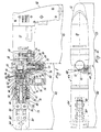
- FIGS 1 and 2 show a pipe swaging device 82 of the invention combined with an operating means 15 of electric motor type.
- the operating means 15 comprises an electric drill 10 of hand type (ie provided with a gun-type handgrip 12), from which the chuck has been removed and replaced with a train of gears (14, 16, 18) which transmit the rotary movement of the motor shaft pinion of the drill 10 to a cam 22, the lateral surface of which engages a cam follower 24 provided with a helical spring 26.
- the cam follower is integral with the end of a plunger 28 of a pump 30, the plunger 28 being movable in both directions within the cylinder 32.
- a rod 52 integral with a piston 54 provided with an 0-ring 56 is slidable in both directions within the cylinder 44.
- the piston 54 divides the interior of the cylinder 44 into two chambers, one of which is the aforesaid first chamber 42, the second chamber being indicated by 58.
- the chambers 42 and 58 in which the same liquid contained in the reservoir 34 is present, are of variable volume in the sense that their volume depends on the position of the rod 52 and relative piston 54.
- the liquid contained in the reservoir 34 is gradually fed under pressure into the first chamber 42. Consequently on the right face (with reference to Figure 1) of the piston 54 there is a greater pressure than on its opposite face. This causes the piston 54 and its rod 52 to move towards the left.
- the rod 52 is hollow and contains a ball valve 68 maintained closed by the elastic reaction force of a precompressed spring 62, which when overcome results in the first chamber 42 communicating (via the channel 50) with the second chamber 58 and hence with the reservoir 34 via a second channel 72, to hence equalize the pressure in the two chambers 42 and 58. In this manner unwanted and dangerous overpressures in the first chamber 42 are prevented.
- the valve 68 can be adjusted by varying the extent by which a grub screw 67 is screwed into a partially threaded internal cavity 71 in the rod 52.
- the rod 52 has an annular step 60 which operates as a stop by abutting against the left end wall 70 of the cylinder 44 when the piston has moved completely to the left.
- a portion of the inner wall of the reservoir 34 is deformable, this deformable portion consisting of a cup-shaped elastic membrane 74 (for example of a suitable rubber or plastic), sealedly locked in position by a cover 76 having a through hole 78 so that the pressure which acts on the outside of the membrane 74 is atmospheric.
- the elastic membrane allows compensation of the incompressible liquid volumes involved.
- a fork 84 which is rotatable relative to the cylinder 44, the axis of rotation of the fork 84 coinciding with that of the rod 52.
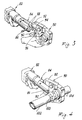
- two idle rollers 80 which, when the rod 52 advances towards the left, engage the respective jaws 92 ( Figures 3 and 4) of a conventional pipe swaging gripper 90 applicable to the pipe swaging device 82. It is applied as shown in Figure 3, ie by inserting the shank 94 of the pipe swaging gripper 90 into the fork 84 (the gripper could also comprise two such shanks, the description being equally valid).
- connection pin 86 is then inserted into the holes 88 provided in the arms of the fork 84 and into the corresponding hole 96 in the shank 94 (or into the corresponding holes in the two said shanks).
- the jaw 92 of the gripper 90 is opened manually in the usual manner and the pipe to be swaged is positioned between the jaws 92 (the illustrated embodiment shows a sleeve into which two pieces of metal pipe 102 and 104 to be connected together have been previously inserted).
- the electric motor of the drill 10 is operated (by pressing the pushbutton 11 with a finger of the hand holding the handgrip 12) to cause the rollers 80 to advance (to the position indicated by 80') and make contact with the interior of the respective jaws 92 (not shown open for simplicity in Figures 3 and 4), so that these latter close to squeeze the sleeve in the corresponding position.
- the pushbutton 11 is released.
- the rod 52 has not reached its end-of-travel position the incompressible liquid in the first chamber 42 remains under pressure, so that the jaws 92 remain closed.
- a handwheel 49 has to be unscrewed, this handwheel when screwed down maintaining the ball valve 51 in position so as to interrupt communication with the conduit 53 which connects the conduit 48 to the reservoir 34.
- the opening of the valve 51 consequent on the unscrewing of the handwheel 49 causes the pressure in the first chamber 42 to equal the pressure in the second chamber 58, so that a return spring 55 mounted coaxial with the rod 52 returns this latter to its rest position, so releasing the jaws 92.
- the illustrated pipe swaging device 82 comprises a means for orientating the fork 84 in predetermined angular positions relative to the cylinder 44.
- Figure 1 shows by way of example a positioning device of the aforesaid type consisting of a ball 83 pressed against the fork 84 by a precompressed spring, a notch 73 which the ball 83 can partly enter being provided in the surface of the fork 84 in the required angular positions (for example every 30 degrees).
- the aforedescribed pipe swaging device has great power and is of much smaller dimensions and weight than known motorized pipe swaging devices, in addition to being simple to use and subject to much less wear than known pipe swaging devices.
Landscapes
- Engineering & Computer Science (AREA)
- Mechanical Engineering (AREA)
- Forging (AREA)
- Fluid-Pressure Circuits (AREA)
- Rigid Pipes And Flexible Pipes (AREA)
- Surgical Instruments (AREA)
- Actuator (AREA)
Claims (6)
- Appareil à refouler les tuyaux métalliques (100) comportant un mors de refoulement conventionnel (90) à deux mâchoires (92) et un dispositif (82) destiné à actionner le mors (90) et comportant deux galets (80) montés à une extrémité d'une tige (52) se déplaçant axialement dans les deux sens et pouvant être poussée dans l'un de ces deux sens de façon à mettre chaque galet (80) en contact avec la partie arrière intérieure correspondante d'une des mâchoires (92), provoquant ainsi la fermeture des mâchoires (92), le dispositif (82) comportant également une transmission hydraulique comprenant :ladite transmission hydraulique comprenant en outre :un cylindre (44) à l'intérieur duquel se déplace la tige (52) portant les galets (80), lesquels dépassent du cylindre (44) par une ouverture appropriée pourvue d'un joint, l'autre extrémité de la tige (52) étant reliée coaxialement à un piston (54) pourvu de joints, l'appareil étant caractérisé en ce que ledit piston (54) divise l'intérieur du cylindre (44) en une première chambre (42) et une deuxième chambre (58) contenant toutes deux un liquide incompressible, une augmentation de volume dans la première chambre (42) provoquant la fermeture des mâchoires (92),ledit appareil étant en outre caractérisé en ce que le moteur électrique entraínant la pompe (30) est celui d'une perceuse électrique portative (10) pouvant être fixée au boítier de l'appareil (82) une fois le mandrin de perçage retiré et remplacé par un train d'engrenages (20, 14, 16, 18) qui transmet le mouvement rotatif de l'arbre de la perceuse (10) à une came (22) sur la périphérie de laquelle porte un poussoir (24) en liaison rigide avec l'extrémité extérieure de la tige de la pompe à piston (30).un réservoir (34) contenant lui aussi ledit liquide incompressible et possédant une partie (74) déformable élastiquement au sein d'une plage prédéterminée lors des variations de la quantité de liquide présent dans le réservoir (34),une pompe à piston (30) actionnée par un moteur électrique, qui puise le liquide dans le réservoir (34) et l'envoie sous pression dans la première chambre (42) du cylindre (44) via un premier passage (36, 46, 48),un deuxième passage (72) reliant la deuxième chambre (58) du cylindre (44) au réservoir (34),un troisième passage (53) reliant la première chambre (42) au réservoir (34) sans passer par la pompe (30),un dispositif d'obturation à action manuelle (51, 49) installé dans le troisième passage (53), etun dispositif de rappel élastique (55) ramenant la tige (52) à la position correspondant au volume minimum de la première chambre (42) du cylindre (44) lorsque le dispositif d'obturation (51, 49) du troisième passage (53) est ouvert,
- Appareil selon la revendication 1, caractérisé en ce que la partie élastiquement déformable de la paroi du réservoir (34) est une membrane élastique (74) .
- Appareil selon l'une quelconque des revendications précédentes, comprenant une soupape de sécurité (68) permettant d'évacuer le liquide incompressible de la première chambre (42) dans la deuxième (58) lorsque la tige (52) du cylindre (44) atteint sa position de fin de course, c'est-à-dire son extension maximum à l'extérieur.
- Appareil selon la revendication 3, caractérisé en ce que la soupape de sécurité (68) est réglable.
- Appareil selon l'une quelconque des revendications précédentes, caractérisé en ce que le dispositif d'obturation à action manuelle est une molette (48), laquelle, lorsqu'on la dévisse, ouvre un clapet à bille (51) fermant le troisième passage (53).
- Appareil selon la revendication 1, caractérisé en ce que les galets (80) sont disposés entre les deux bras d'une fourche (84) montée libre en rotation sur le cylindre (44), l'axe de rotation de la fourche (84) coïncidant avec celui de la tige (52).
Applications Claiming Priority (2)
| Application Number | Priority Date | Filing Date | Title |
|---|---|---|---|
| IT97MI002312A IT1295321B1 (it) | 1997-10-13 | 1997-10-13 | Dispositivo strozzatubi a trasmissione idraulica |
| ITMI972312 | 1997-10-13 |
Publications (2)
| Publication Number | Publication Date |
|---|---|
| EP0908657A1 EP0908657A1 (fr) | 1999-04-14 |
| EP0908657B1 true EP0908657B1 (fr) | 2001-05-23 |
Family
ID=11378032
Family Applications (1)
| Application Number | Title | Priority Date | Filing Date |
|---|---|---|---|
| EP98118890A Expired - Lifetime EP0908657B1 (fr) | 1997-10-13 | 1998-10-06 | Machine à rétreindre de tuyaux à transmission hydraulique |
Country Status (5)
| Country | Link |
|---|---|
| EP (1) | EP0908657B1 (fr) |
| AT (1) | ATE201491T1 (fr) |
| DE (1) | DE69800825T2 (fr) |
| ES (1) | ES2157108T3 (fr) |
| IT (1) | IT1295321B1 (fr) |
Families Citing this family (9)
| Publication number | Priority date | Publication date | Assignee | Title |
|---|---|---|---|---|
| IT1316351B1 (it) * | 2000-02-07 | 2003-04-10 | Cbc Spa | Dispositivo strozzatubi a trasmissione idraulica automatico |
| DE50111613D1 (de) | 2000-05-25 | 2007-01-25 | Arx Ag | Presswerkzeug für die Verpressung von Kupplungselementen |
| WO2007010339A2 (fr) * | 2005-07-19 | 2007-01-25 | Pi.Effe.Ci. S.R.L. | Outil conçu pour le raccordement de tubes au moyen de manchons de raccordement |
| DE102006003044B4 (de) * | 2006-01-23 | 2015-10-08 | Gustav Klauke Gmbh | Hydraulisch angetriebenes Verpressgerät sowie Verfahren zum Verpressen eines Fittings |
| DE102007005837B4 (de) * | 2006-02-03 | 2016-04-07 | Novopress Gmbh Pressen Und Presswerkzeuge & Co. Kg | Antriebseinheit für ein Preßgerät |
| DE202006001889U1 (de) * | 2006-02-03 | 2007-03-08 | Novopress Gmbh Pressen Und Presswerkzeuge & Co. Kg | Antriebseinheit für ein Preßgerät |
| DE102007030644A1 (de) * | 2007-07-02 | 2009-01-08 | Gustav Klauke Gmbh | Hydraulisch betätigbares Handwerkzeug |
| CN109676913B (zh) * | 2018-12-29 | 2024-06-07 | 张家港市剑泉工具制造有限公司 | 一种钳子手柄套自动套装装置 |
| CN117388083B (zh) * | 2023-12-13 | 2024-02-13 | 常州森鸿装饰材料股份有限公司 | 一种地板强度检测装置 |
Family Cites Families (4)
| Publication number | Priority date | Publication date | Assignee | Title |
|---|---|---|---|---|
| US2869407A (en) * | 1954-10-15 | 1959-01-20 | Greenlee Bros & Co | Portable metal working tool |
| DE2136782C2 (de) * | 1971-07-23 | 1982-12-02 | Novopress GmbH Pressen und Presswerkzeuge & Co KG, 4000 Düsseldorf | Tragbares druckmittelbetriebenes Klemmwerkzeug |
| EP0389716B1 (fr) * | 1989-03-31 | 1994-05-18 | Japan Storage Battery Company Limited | Mécanisme à came et outil hydraulique motorisé |
| IT237303Y1 (it) * | 1995-11-23 | 2000-09-05 | Cbc Spa | Apparecchio curvatubi a trasmissione idraulica |
-
1997
- 1997-10-13 IT IT97MI002312A patent/IT1295321B1/it active IP Right Grant
-
1998
- 1998-10-06 DE DE69800825T patent/DE69800825T2/de not_active Expired - Lifetime
- 1998-10-06 ES ES98118890T patent/ES2157108T3/es not_active Expired - Lifetime
- 1998-10-06 EP EP98118890A patent/EP0908657B1/fr not_active Expired - Lifetime
- 1998-10-06 AT AT98118890T patent/ATE201491T1/de active
Also Published As
| Publication number | Publication date |
|---|---|
| IT1295321B1 (it) | 1999-05-04 |
| ES2157108T3 (es) | 2001-08-01 |
| DE69800825T2 (de) | 2001-09-27 |
| DE69800825D1 (de) | 2001-06-28 |
| ITMI972312A1 (it) | 1999-04-13 |
| ATE201491T1 (de) | 2001-06-15 |
| EP0908657A1 (fr) | 1999-04-14 |
Similar Documents
| Publication | Publication Date | Title |
|---|---|---|
| EP0908657B1 (fr) | Machine à rétreindre de tuyaux à transmission hydraulique | |
| US4805496A (en) | Hydraulic power wrench | |
| US5425164A (en) | Hand-tool system for installing blind fasteners | |
| US4587732A (en) | Cable cutting and crimping | |
| EP1339509A1 (fr) | Outil de sertissage portatif | |
| EP1910035B1 (fr) | Outil conçu pour le raccordement de tubes au moyen de manchons de raccordement | |
| CN101124069B (zh) | 液压手动工具 | |
| GB2042335A (en) | Modular fire fighting apparatus | |
| US8151666B1 (en) | Twist throttle with integral hydraulic master cylinder | |
| JPS62296925A (ja) | 液圧クリンプ加工工具 | |
| US4151720A (en) | Manually operable hydraulic actuator | |
| GB2112874A (en) | Hydraulic jacks | |
| US4667502A (en) | Hydraulic compression apparatus | |
| US5894667A (en) | Hand tools | |
| CN111140561A (zh) | 用于压机的液压式泵-阀装置 | |
| EP1859749A2 (fr) | Instrument chirurgical activée par gaz sous pression | |
| US20180161845A1 (en) | Hydraulic tool | |
| US4149381A (en) | Single hand operated tool | |
| RU2509211C2 (ru) | Устройство для подсоединения подводящей трубы к внутреннему каналу анкерного болта | |
| EP1121997B1 (fr) | Machine automatique à rétreindre de tuyaux à transmission hydraulique | |
| CN205219041U (zh) | 液压工具 | |
| KR102239876B1 (ko) | 산업용 약액저장탱크 뚜껑의 소형 안전개폐장치 | |
| US4745831A (en) | Setting tool for screwing-in threaded rods | |
| JPH0741544B2 (ja) | パワーレンチ | |
| EP0220639B1 (fr) | Dispositif de pliage de tubes à commande hydraulique pouvant être actionné d'une seule main |
Legal Events
| Date | Code | Title | Description |
|---|---|---|---|
| PUAI | Public reference made under article 153(3) epc to a published international application that has entered the european phase |
Free format text: ORIGINAL CODE: 0009012 |
|
| AK | Designated contracting states |
Kind code of ref document: A1 Designated state(s): AT DE ES FR GB IT SE |
|
| AX | Request for extension of the european patent |
Free format text: AL;LT;LV;MK;RO;SI |
|
| 17P | Request for examination filed |
Effective date: 19990721 |
|
| AKX | Designation fees paid |
Free format text: AT DE ES FR GB IT SE |
|
| 17Q | First examination report despatched |
Effective date: 19991228 |
|
| GRAG | Despatch of communication of intention to grant |
Free format text: ORIGINAL CODE: EPIDOS AGRA |
|
| GRAG | Despatch of communication of intention to grant |
Free format text: ORIGINAL CODE: EPIDOS AGRA |
|
| GRAH | Despatch of communication of intention to grant a patent |
Free format text: ORIGINAL CODE: EPIDOS IGRA |
|
| GRAH | Despatch of communication of intention to grant a patent |
Free format text: ORIGINAL CODE: EPIDOS IGRA |
|
| GRAA | (expected) grant |
Free format text: ORIGINAL CODE: 0009210 |
|
| AK | Designated contracting states |
Kind code of ref document: B1 Designated state(s): AT DE ES FR GB IT SE |
|
| REF | Corresponds to: |
Ref document number: 201491 Country of ref document: AT Date of ref document: 20010615 Kind code of ref document: T |
|
| REF | Corresponds to: |
Ref document number: 69800825 Country of ref document: DE Date of ref document: 20010628 |
|
| REG | Reference to a national code |
Ref country code: ES Ref legal event code: FG2A Ref document number: 2157108 Country of ref document: ES Kind code of ref document: T3 |
|
| ITF | It: translation for a ep patent filed | ||
| ET | Fr: translation filed | ||
| REG | Reference to a national code |
Ref country code: GB Ref legal event code: IF02 |
|
| PLBE | No opposition filed within time limit |
Free format text: ORIGINAL CODE: 0009261 |
|
| STAA | Information on the status of an ep patent application or granted ep patent |
Free format text: STATUS: NO OPPOSITION FILED WITHIN TIME LIMIT |
|
| 26N | No opposition filed | ||
| PGFP | Annual fee paid to national office [announced via postgrant information from national office to epo] |
Ref country code: ES Payment date: 20130918 Year of fee payment: 16 |
|
| PGFP | Annual fee paid to national office [announced via postgrant information from national office to epo] |
Ref country code: SE Payment date: 20131017 Year of fee payment: 16 Ref country code: DE Payment date: 20131002 Year of fee payment: 16 Ref country code: GB Payment date: 20131025 Year of fee payment: 16 Ref country code: FR Payment date: 20131028 Year of fee payment: 16 Ref country code: AT Payment date: 20131016 Year of fee payment: 16 |
|
| REG | Reference to a national code |
Ref country code: DE Ref legal event code: R119 Ref document number: 69800825 Country of ref document: DE |
|
| REG | Reference to a national code |
Ref country code: SE Ref legal event code: EUG |
|
| REG | Reference to a national code |
Ref country code: AT Ref legal event code: MM01 Ref document number: 201491 Country of ref document: AT Kind code of ref document: T Effective date: 20141006 |
|
| GBPC | Gb: european patent ceased through non-payment of renewal fee |
Effective date: 20141006 |
|
| PG25 | Lapsed in a contracting state [announced via postgrant information from national office to epo] |
Ref country code: GB Free format text: LAPSE BECAUSE OF NON-PAYMENT OF DUE FEES Effective date: 20141006 Ref country code: DE Free format text: LAPSE BECAUSE OF NON-PAYMENT OF DUE FEES Effective date: 20150501 Ref country code: SE Free format text: LAPSE BECAUSE OF NON-PAYMENT OF DUE FEES Effective date: 20141007 |
|
| REG | Reference to a national code |
Ref country code: FR Ref legal event code: ST Effective date: 20150630 |
|
| PG25 | Lapsed in a contracting state [announced via postgrant information from national office to epo] |
Ref country code: AT Free format text: LAPSE BECAUSE OF NON-PAYMENT OF DUE FEES Effective date: 20141006 Ref country code: FR Free format text: LAPSE BECAUSE OF NON-PAYMENT OF DUE FEES Effective date: 20141031 |
|
| REG | Reference to a national code |
Ref country code: ES Ref legal event code: FD2A Effective date: 20151127 |
|
| PG25 | Lapsed in a contracting state [announced via postgrant information from national office to epo] |
Ref country code: ES Free format text: LAPSE BECAUSE OF NON-PAYMENT OF DUE FEES Effective date: 20141007 |
|
| PGFP | Annual fee paid to national office [announced via postgrant information from national office to epo] |
Ref country code: IT Payment date: 20170925 Year of fee payment: 20 |