EP0908664A2 - Verfahren und Systeme zur Abgabe von ultrareinem Gas an einen Verwendungsort - Google Patents
Verfahren und Systeme zur Abgabe von ultrareinem Gas an einen Verwendungsort Download PDFInfo
- Publication number
- EP0908664A2 EP0908664A2 EP98402170A EP98402170A EP0908664A2 EP 0908664 A2 EP0908664 A2 EP 0908664A2 EP 98402170 A EP98402170 A EP 98402170A EP 98402170 A EP98402170 A EP 98402170A EP 0908664 A2 EP0908664 A2 EP 0908664A2
- Authority
- EP
- European Patent Office
- Prior art keywords
- ultra
- high purity
- phase change
- liquid
- effect
- Prior art date
- Legal status (The legal status is an assumption and is not a legal conclusion. Google has not performed a legal analysis and makes no representation as to the accuracy of the status listed.)
- Withdrawn
Links
- 238000000034 method Methods 0.000 title claims abstract description 34
- 239000012071 phase Substances 0.000 claims abstract description 78
- 230000008859 change Effects 0.000 claims abstract description 67
- 239000007788 liquid Substances 0.000 claims abstract description 64
- 230000000694 effects Effects 0.000 claims abstract description 41
- 239000007791 liquid phase Substances 0.000 claims abstract description 22
- 238000010438 heat treatment Methods 0.000 claims description 3
- 238000005086 pumping Methods 0.000 claims description 2
- 238000010276 construction Methods 0.000 claims 1
- 238000005485 electric heating Methods 0.000 claims 1
- 238000009834 vaporization Methods 0.000 abstract description 8
- 230000008016 vaporization Effects 0.000 abstract description 8
- 239000007789 gas Substances 0.000 description 60
- 102100033763 Transducin-like enhancer protein 4 Human genes 0.000 description 52
- 238000009826 distribution Methods 0.000 description 10
- 238000004519 manufacturing process Methods 0.000 description 10
- 239000012535 impurity Substances 0.000 description 8
- 238000009434 installation Methods 0.000 description 7
- 238000003860 storage Methods 0.000 description 7
- IJGRMHOSHXDMSA-UHFFFAOYSA-N Atomic nitrogen Chemical compound N#N IJGRMHOSHXDMSA-UHFFFAOYSA-N 0.000 description 6
- 239000000463 material Substances 0.000 description 6
- 239000004065 semiconductor Substances 0.000 description 6
- 238000005260 corrosion Methods 0.000 description 5
- 230000007797 corrosion Effects 0.000 description 5
- 239000000126 substance Substances 0.000 description 5
- PXHVJJICTQNCMI-UHFFFAOYSA-N Nickel Chemical compound [Ni] PXHVJJICTQNCMI-UHFFFAOYSA-N 0.000 description 4
- 238000000605 extraction Methods 0.000 description 4
- 239000001307 helium Substances 0.000 description 4
- 229910052734 helium Inorganic materials 0.000 description 4
- SWQJXJOGLNCZEY-UHFFFAOYSA-N helium atom Chemical compound [He] SWQJXJOGLNCZEY-UHFFFAOYSA-N 0.000 description 4
- 230000002051 biphasic effect Effects 0.000 description 3
- 238000011109 contamination Methods 0.000 description 3
- 230000001627 detrimental effect Effects 0.000 description 3
- 238000001704 evaporation Methods 0.000 description 3
- 229910052757 nitrogen Inorganic materials 0.000 description 3
- 239000002245 particle Substances 0.000 description 3
- 238000000746 purification Methods 0.000 description 3
- 238000012546 transfer Methods 0.000 description 3
- XKRFYHLGVUSROY-UHFFFAOYSA-N Argon Chemical compound [Ar] XKRFYHLGVUSROY-UHFFFAOYSA-N 0.000 description 2
- 239000000443 aerosol Substances 0.000 description 2
- 239000002274 desiccant Substances 0.000 description 2
- 238000010586 diagram Methods 0.000 description 2
- MROCJMGDEKINLD-UHFFFAOYSA-N dichlorosilane Chemical compound Cl[SiH2]Cl MROCJMGDEKINLD-UHFFFAOYSA-N 0.000 description 2
- 230000008020 evaporation Effects 0.000 description 2
- 235000013305 food Nutrition 0.000 description 2
- 239000011261 inert gas Substances 0.000 description 2
- 239000008263 liquid aerosol Substances 0.000 description 2
- CRSOQBOWXPBRES-UHFFFAOYSA-N neopentane Chemical compound CC(C)(C)C CRSOQBOWXPBRES-UHFFFAOYSA-N 0.000 description 2
- 229910052759 nickel Inorganic materials 0.000 description 2
- 230000008569 process Effects 0.000 description 2
- 230000009467 reduction Effects 0.000 description 2
- 238000001179 sorption measurement Methods 0.000 description 2
- 229910001220 stainless steel Inorganic materials 0.000 description 2
- 239000010935 stainless steel Substances 0.000 description 2
- TXEYQDLBPFQVAA-UHFFFAOYSA-N tetrafluoromethane Chemical class FC(F)(F)F TXEYQDLBPFQVAA-UHFFFAOYSA-N 0.000 description 2
- ZDHXKXAHOVTTAH-UHFFFAOYSA-N trichlorosilane Chemical compound Cl[SiH](Cl)Cl ZDHXKXAHOVTTAH-UHFFFAOYSA-N 0.000 description 2
- 239000005052 trichlorosilane Substances 0.000 description 2
- 239000006200 vaporizer Substances 0.000 description 2
- 229910000792 Monel Inorganic materials 0.000 description 1
- 101000916532 Rattus norvegicus Zinc finger and BTB domain-containing protein 38 Proteins 0.000 description 1
- 229910052786 argon Inorganic materials 0.000 description 1
- 230000009286 beneficial effect Effects 0.000 description 1
- 238000009530 blood pressure measurement Methods 0.000 description 1
- 238000009529 body temperature measurement Methods 0.000 description 1
- 239000003638 chemical reducing agent Substances 0.000 description 1
- 150000001875 compounds Chemical class 0.000 description 1
- 238000001816 cooling Methods 0.000 description 1
- 238000007872 degassing Methods 0.000 description 1
- 238000013461 design Methods 0.000 description 1
- 238000001035 drying Methods 0.000 description 1
- 238000001914 filtration Methods 0.000 description 1
- 239000007792 gaseous phase Substances 0.000 description 1
- 229910000856 hastalloy Inorganic materials 0.000 description 1
- 229910052743 krypton Inorganic materials 0.000 description 1
- DNNSSWSSYDEUBZ-UHFFFAOYSA-N krypton atom Chemical compound [Kr] DNNSSWSSYDEUBZ-UHFFFAOYSA-N 0.000 description 1
- 238000012423 maintenance Methods 0.000 description 1
- 238000005259 measurement Methods 0.000 description 1
- 239000002184 metal Substances 0.000 description 1
- 229910052751 metal Inorganic materials 0.000 description 1
- 239000003595 mist Substances 0.000 description 1
- 239000000203 mixture Substances 0.000 description 1
- 238000012986 modification Methods 0.000 description 1
- 230000004048 modification Effects 0.000 description 1
- 229910052754 neon Inorganic materials 0.000 description 1
- GKAOGPIIYCISHV-UHFFFAOYSA-N neon atom Chemical compound [Ne] GKAOGPIIYCISHV-UHFFFAOYSA-N 0.000 description 1
- 238000004806 packaging method and process Methods 0.000 description 1
- 230000000704 physical effect Effects 0.000 description 1
- 238000012545 processing Methods 0.000 description 1
- 238000010926 purge Methods 0.000 description 1
- 230000001105 regulatory effect Effects 0.000 description 1
- 230000000930 thermomechanical effect Effects 0.000 description 1
- VPAYJEUHKVESSD-UHFFFAOYSA-N trifluoroiodomethane Chemical compound FC(F)(F)I VPAYJEUHKVESSD-UHFFFAOYSA-N 0.000 description 1
Images
Classifications
-
- F—MECHANICAL ENGINEERING; LIGHTING; HEATING; WEAPONS; BLASTING
- F17—STORING OR DISTRIBUTING GASES OR LIQUIDS
- F17C—VESSELS FOR CONTAINING OR STORING COMPRESSED, LIQUEFIED OR SOLIDIFIED GASES; FIXED-CAPACITY GAS-HOLDERS; FILLING VESSELS WITH, OR DISCHARGING FROM VESSELS, COMPRESSED, LIQUEFIED, OR SOLIDIFIED GASES
- F17C7/00—Methods or apparatus for discharging liquefied, solidified, or compressed gases from pressure vessels, not covered by another subclass
- F17C7/02—Discharging liquefied gases
- F17C7/04—Discharging liquefied gases with change of state, e.g. vaporisation
-
- F—MECHANICAL ENGINEERING; LIGHTING; HEATING; WEAPONS; BLASTING
- F17—STORING OR DISTRIBUTING GASES OR LIQUIDS
- F17C—VESSELS FOR CONTAINING OR STORING COMPRESSED, LIQUEFIED OR SOLIDIFIED GASES; FIXED-CAPACITY GAS-HOLDERS; FILLING VESSELS WITH, OR DISCHARGING FROM VESSELS, COMPRESSED, LIQUEFIED, OR SOLIDIFIED GASES
- F17C2205/00—Vessel construction, in particular mounting arrangements, attachments or identifications means
- F17C2205/03—Fluid connections, filters, valves, closure means or other attachments
- F17C2205/0302—Fittings, valves, filters, or components in connection with the gas storage device
- F17C2205/0323—Valves
- F17C2205/0332—Safety valves or pressure relief valves
-
- F—MECHANICAL ENGINEERING; LIGHTING; HEATING; WEAPONS; BLASTING
- F17—STORING OR DISTRIBUTING GASES OR LIQUIDS
- F17C—VESSELS FOR CONTAINING OR STORING COMPRESSED, LIQUEFIED OR SOLIDIFIED GASES; FIXED-CAPACITY GAS-HOLDERS; FILLING VESSELS WITH, OR DISCHARGING FROM VESSELS, COMPRESSED, LIQUEFIED, OR SOLIDIFIED GASES
- F17C2205/00—Vessel construction, in particular mounting arrangements, attachments or identifications means
- F17C2205/03—Fluid connections, filters, valves, closure means or other attachments
- F17C2205/0302—Fittings, valves, filters, or components in connection with the gas storage device
- F17C2205/0338—Pressure regulators
-
- F—MECHANICAL ENGINEERING; LIGHTING; HEATING; WEAPONS; BLASTING
- F17—STORING OR DISTRIBUTING GASES OR LIQUIDS
- F17C—VESSELS FOR CONTAINING OR STORING COMPRESSED, LIQUEFIED OR SOLIDIFIED GASES; FIXED-CAPACITY GAS-HOLDERS; FILLING VESSELS WITH, OR DISCHARGING FROM VESSELS, COMPRESSED, LIQUEFIED, OR SOLIDIFIED GASES
- F17C2205/00—Vessel construction, in particular mounting arrangements, attachments or identifications means
- F17C2205/03—Fluid connections, filters, valves, closure means or other attachments
- F17C2205/0388—Arrangement of valves, regulators, filters
-
- F—MECHANICAL ENGINEERING; LIGHTING; HEATING; WEAPONS; BLASTING
- F17—STORING OR DISTRIBUTING GASES OR LIQUIDS
- F17C—VESSELS FOR CONTAINING OR STORING COMPRESSED, LIQUEFIED OR SOLIDIFIED GASES; FIXED-CAPACITY GAS-HOLDERS; FILLING VESSELS WITH, OR DISCHARGING FROM VESSELS, COMPRESSED, LIQUEFIED, OR SOLIDIFIED GASES
- F17C2221/00—Handled fluid, in particular type of fluid
- F17C2221/01—Pure fluids
- F17C2221/014—Nitrogen
-
- F—MECHANICAL ENGINEERING; LIGHTING; HEATING; WEAPONS; BLASTING
- F17—STORING OR DISTRIBUTING GASES OR LIQUIDS
- F17C—VESSELS FOR CONTAINING OR STORING COMPRESSED, LIQUEFIED OR SOLIDIFIED GASES; FIXED-CAPACITY GAS-HOLDERS; FILLING VESSELS WITH, OR DISCHARGING FROM VESSELS, COMPRESSED, LIQUEFIED, OR SOLIDIFIED GASES
- F17C2221/00—Handled fluid, in particular type of fluid
- F17C2221/01—Pure fluids
- F17C2221/016—Noble gases (Ar, Kr, Xe)
-
- F—MECHANICAL ENGINEERING; LIGHTING; HEATING; WEAPONS; BLASTING
- F17—STORING OR DISTRIBUTING GASES OR LIQUIDS
- F17C—VESSELS FOR CONTAINING OR STORING COMPRESSED, LIQUEFIED OR SOLIDIFIED GASES; FIXED-CAPACITY GAS-HOLDERS; FILLING VESSELS WITH, OR DISCHARGING FROM VESSELS, COMPRESSED, LIQUEFIED, OR SOLIDIFIED GASES
- F17C2221/00—Handled fluid, in particular type of fluid
- F17C2221/01—Pure fluids
- F17C2221/016—Noble gases (Ar, Kr, Xe)
- F17C2221/017—Helium
-
- F—MECHANICAL ENGINEERING; LIGHTING; HEATING; WEAPONS; BLASTING
- F17—STORING OR DISTRIBUTING GASES OR LIQUIDS
- F17C—VESSELS FOR CONTAINING OR STORING COMPRESSED, LIQUEFIED OR SOLIDIFIED GASES; FIXED-CAPACITY GAS-HOLDERS; FILLING VESSELS WITH, OR DISCHARGING FROM VESSELS, COMPRESSED, LIQUEFIED, OR SOLIDIFIED GASES
- F17C2221/00—Handled fluid, in particular type of fluid
- F17C2221/05—Ultrapure fluid
-
- F—MECHANICAL ENGINEERING; LIGHTING; HEATING; WEAPONS; BLASTING
- F17—STORING OR DISTRIBUTING GASES OR LIQUIDS
- F17C—VESSELS FOR CONTAINING OR STORING COMPRESSED, LIQUEFIED OR SOLIDIFIED GASES; FIXED-CAPACITY GAS-HOLDERS; FILLING VESSELS WITH, OR DISCHARGING FROM VESSELS, COMPRESSED, LIQUEFIED, OR SOLIDIFIED GASES
- F17C2223/00—Handled fluid before transfer, i.e. state of fluid when stored in the vessel or before transfer from the vessel
- F17C2223/01—Handled fluid before transfer, i.e. state of fluid when stored in the vessel or before transfer from the vessel characterised by the phase
- F17C2223/0146—Two-phase
- F17C2223/0153—Liquefied gas, e.g. LPG, GPL
-
- F—MECHANICAL ENGINEERING; LIGHTING; HEATING; WEAPONS; BLASTING
- F17—STORING OR DISTRIBUTING GASES OR LIQUIDS
- F17C—VESSELS FOR CONTAINING OR STORING COMPRESSED, LIQUEFIED OR SOLIDIFIED GASES; FIXED-CAPACITY GAS-HOLDERS; FILLING VESSELS WITH, OR DISCHARGING FROM VESSELS, COMPRESSED, LIQUEFIED, OR SOLIDIFIED GASES
- F17C2225/00—Handled fluid after transfer, i.e. state of fluid after transfer from the vessel
- F17C2225/01—Handled fluid after transfer, i.e. state of fluid after transfer from the vessel characterised by the phase
- F17C2225/0107—Single phase
- F17C2225/0123—Single phase gaseous, e.g. CNG, GNC
-
- F—MECHANICAL ENGINEERING; LIGHTING; HEATING; WEAPONS; BLASTING
- F17—STORING OR DISTRIBUTING GASES OR LIQUIDS
- F17C—VESSELS FOR CONTAINING OR STORING COMPRESSED, LIQUEFIED OR SOLIDIFIED GASES; FIXED-CAPACITY GAS-HOLDERS; FILLING VESSELS WITH, OR DISCHARGING FROM VESSELS, COMPRESSED, LIQUEFIED, OR SOLIDIFIED GASES
- F17C2227/00—Transfer of fluids, i.e. method or means for transferring the fluid; Heat exchange with the fluid
- F17C2227/03—Heat exchange with the fluid
- F17C2227/0337—Heat exchange with the fluid by cooling
- F17C2227/0358—Heat exchange with the fluid by cooling by expansion
- F17C2227/0362—Heat exchange with the fluid by cooling by expansion in a turbine
-
- F—MECHANICAL ENGINEERING; LIGHTING; HEATING; WEAPONS; BLASTING
- F17—STORING OR DISTRIBUTING GASES OR LIQUIDS
- F17C—VESSELS FOR CONTAINING OR STORING COMPRESSED, LIQUEFIED OR SOLIDIFIED GASES; FIXED-CAPACITY GAS-HOLDERS; FILLING VESSELS WITH, OR DISCHARGING FROM VESSELS, COMPRESSED, LIQUEFIED, OR SOLIDIFIED GASES
- F17C2227/00—Transfer of fluids, i.e. method or means for transferring the fluid; Heat exchange with the fluid
- F17C2227/04—Methods for emptying or filling
- F17C2227/045—Methods for emptying or filling by vacuum
-
- F—MECHANICAL ENGINEERING; LIGHTING; HEATING; WEAPONS; BLASTING
- F17—STORING OR DISTRIBUTING GASES OR LIQUIDS
- F17C—VESSELS FOR CONTAINING OR STORING COMPRESSED, LIQUEFIED OR SOLIDIFIED GASES; FIXED-CAPACITY GAS-HOLDERS; FILLING VESSELS WITH, OR DISCHARGING FROM VESSELS, COMPRESSED, LIQUEFIED, OR SOLIDIFIED GASES
- F17C2250/00—Accessories; Control means; Indicating, measuring or monitoring of parameters
- F17C2250/06—Controlling or regulating of parameters as output values
- F17C2250/0605—Parameters
- F17C2250/0636—Flow or movement of content
-
- F—MECHANICAL ENGINEERING; LIGHTING; HEATING; WEAPONS; BLASTING
- F17—STORING OR DISTRIBUTING GASES OR LIQUIDS
- F17C—VESSELS FOR CONTAINING OR STORING COMPRESSED, LIQUEFIED OR SOLIDIFIED GASES; FIXED-CAPACITY GAS-HOLDERS; FILLING VESSELS WITH, OR DISCHARGING FROM VESSELS, COMPRESSED, LIQUEFIED, OR SOLIDIFIED GASES
- F17C2260/00—Purposes of gas storage and gas handling
- F17C2260/03—Dealing with losses
- F17C2260/035—Dealing with losses of fluid
- F17C2260/036—Avoiding leaks
-
- F—MECHANICAL ENGINEERING; LIGHTING; HEATING; WEAPONS; BLASTING
- F17—STORING OR DISTRIBUTING GASES OR LIQUIDS
- F17C—VESSELS FOR CONTAINING OR STORING COMPRESSED, LIQUEFIED OR SOLIDIFIED GASES; FIXED-CAPACITY GAS-HOLDERS; FILLING VESSELS WITH, OR DISCHARGING FROM VESSELS, COMPRESSED, LIQUEFIED, OR SOLIDIFIED GASES
- F17C2270/00—Applications
- F17C2270/05—Applications for industrial use
- F17C2270/0518—Semiconductors
Definitions
- This invention pertains in general to the delivery of ultra-pure gases, primarily reactive gases, to a point of use. More specifically, this invention relates to methods and systems to deliver ultra-pure gases which are liquefied at room temperature with a vapor pressure above atmospheric pressure to semiconductor tools and other points of use.
- Ultra-high purity (UHP) electronics specialty gases are needed for the integrated circuit (IC) manufacturing industry.
- Typical purity requirements at state of the art manufacturing are 10-100 parts per billion (ppb) for molecular impurities, less than 1 particle/M 3 of size greater than 0.05 micrometer, and 10-1000 parts per trillion (ppt) for metallic impurities, in accordance with the recently published SIA Roadmap.
- high mass flow rate gas delivery involves the extraction of a biphasic gas-liquid aerosol from the storage container of pressurized liquid ESG, because the energy of vaporization is difficult to compensate in practice from an external heat source.
- One aspect of the invention is a method of delivering an ultra-high purity gas, preferably an ESG, from a first station to a second station distal from the first station (the second station preferably being a point of use in a semiconductor fab), the method comprising the steps of:
- the phase change is performed "on-demand" by the second station or point of use, and the phase change rate is preferably controlled in real time via computer control or other real-time control means.
- a plurality of means to effect phase change also sometimes referred to herein as vaporizers or evaporators
- vaporizers or evaporators are employed, each preferably servicing a dedicated point of use, although it is also within the invention to have more than one phase change means assigned to a single point of use.
- At least the transporting and phase change steps are performed in double-wall conduits and vessels.
- Another aspect of the invention includes systems for delivering ultra-high purity gas, preferably an ESG, from a first station to a second station distal from the first station (the second station preferably being a point of use in a semiconductor fab), the system comprising:
- ultra-high purity means a gas or liquid having 10-100 parts per billion (ppb) molecular impurities less than 1 particle/M 3 of size greater than 0.05 micrometer, and 10-1000 parts per trillion (ppt) for metallic impurities, in accordance with the recently published SIA Roadmap.
- ppb parts per billion
- ppt parts per trillion
- ultra-high purity gases and liquids preferably having less than 10 ppb molecular impurities, and preferably less than 10 ppt metallic impurities.
- the methods and systems of the invention combine the advantages of bulk supply and of clean liquid phase ESG vaporization in answering the need for increasingly high mass flow delivery rates of ultra-high purity ESG's for IC manufacturing. Further understanding of the invention may be had by reviewing the drawing and description of preferred embodiments.
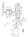
- FIG. 1 is a schematic process flow diagram of a method and system in accordance with the invention.
- the second station referred to in the Summary of the Invention is simply referred to as the "point of use", it being understood that in certain embodiments there may exist equipment (for example valves, flow meters, buffer vessels, holding vessels) downstream of the vaporizer, before the actual point of use, these method and system embodiments being deemed to be within the present invention, to the extent that the intermediate equipment does not contribute impurities sufficient to make the ultra-high purity gas unacceptable to the end user. In other words some minimal de minimus amount of impurity generation may be acceptable.
- equipment for example valves, flow meters, buffer vessels, holding vessels
- a bulk pressurized-liquid phase ESG container 12 contains ultra-high purity liquid ESG having the purity attributes previously defined, obtained, for example, from a purification plant.
- Gas pressure is applied to container 12 through a conduit 14, the pressure preferably being precisely regulated.
- the gas supplied through conduit 14 is preferably inert and may be selected from any gas that is sufficiently inert to the material of container 12, conduit 14 and liquid ESG in container 12.
- Gas supplied through conduit 14 may be, for example helium, argon, nitrogen, krypton, zenon, neon, or mixtures of two or more of these. Particularly preferred is ultra-high purity helium.
- Container 12 is designed to maintain the necessary pressures and temperatures required to maintain a variety of ESGs in liquid form.
- Container 12 is preferably made of material and with an internal surface finishing appropriate to be inert to the ultra-high purity liquid ESG.
- 316 L stainless steel which is electropolished and/or coated by an electroless deposited nickel film, or Hastelloy, Monel, nickel or other similar corrosion resistant materials are preferably employed.
- the surfaces exposed or to be exposed to the ultra-high purity liquid and gaseous ESG are treated in accordance with assignee's treatment procedures detailed in assignee's issued United States Patent Numbers 5,591,273 and 5, , which are incorporated by reference herein in their entirety.
- the ultra-high purity ESG is transported, preferably at high mass flow rate preferably ranging from about 0.1 standard liter per minute (slm) to about 10,000_slm, more preferably ranging from about 1 slm to about 100 slm, in substantially its liquid phase from container 12, through transport means 16a, 16b, 16c, ... 16n, to one or more means to effect phase change 20a, 20b, 20c, ... 20n (only one illustrated in FIG. 1).
- the actual flow rates will depend on the demands of the point of use, as explained further herein.
- Means to effect phase change 20 are preferably located close to the point of use of the ultra-high purity ESG in gas phase. Liquid mass flow controllers 18a, 18b, 18c, ...
- Each means to effect phase change 20 has a space 22 into which the ultra-high purity, substantially liquid ESG 24 is evaporated, preferably at or near room temperature (about 25 °C).
- the gaseous ESG then flows through appropriately inerted conduit 26 toward the point of use. Downstream of each evaporator 20, the ESG gas pressure is reduced to the desired working pressure at the point of use 30 (or to a slightly higher pressure, for example if there exists a buffer vessel between phase change means 20 and the point of use 30) using a pressure regulator 28.
- Gas mass flow rate of ESG to the processing tools or other points of use 30 is controlled by conventional mass flow controllers (not illustrated).
- All parts of components 16, 18, 20, 26, and 28 that may come in contact with the ESG are made of corrosion resistant materials which present inert surfaces against the specific ESG. Materials and procedures for ensuring that the surfaces exposed to the ESG are inert are identical to those described above for container 12.
- mass flow-control instrumentation is significantly easier to design and construct with the required corrosion resistance properties and precision for a liquid phase distribution system than for the corresponding gas phase distribution system.
- the bulk liquid ESG flow is preferably divided into a plurality of branches conducting to a series of phase change devices, represented in FIG. 1 by 20a, 20b, and 20c (commonly referred to as evaporators), in which the pressurized-liquid phase ESG is converted into gas phase.
- evaporators commonly referred to as evaporators
- this is performed at or near practical equilibrium vaporization conditions; in other words the thermal energy transfer from the external environment to the liquid ESG essentially equals the energy of vaporization.
- the practical limiting conditions are independently established experimentally for each chemical compound by checking the absence of emission of an aerosol from the evaporator.
- the specific number of evaporators (20n) needed for a specific installation is decided on the basis of the ESG gas flow needed for points of use 30 used in the manufacturing process and from the preferred criterion of "equilibrium vaporization", which dictates a practical upper limit for the gas mass flow rate-gas usage cycle time under which monophasic gas phase ESG is extracted.
- the volume of the liquid phase storage in container 12 (which may in fact be two or more containers, for example when a spare or redundant container is employed) is dictated by a compromise between the mass consumption rate at the point of use 30 and safety considerations, knowing that bulk container storage exchange will be minimized for both safety, cost and contamination control considerations.
- Liquid phase ultra-high purity ESG is flowed into each means to effect phase change 20 at a mass flow rate that is sufficient that liquid phase and gas phase always coexist in means to effect phase change 20.
- a slight inert gas pressure preferably ultra-high purity helium is applied in container 12, as described previously.
- the whole system 10 can operate based on pressure difference driven flows and manual setting of the pressure and flow control equipment, in practice, the gas flow cycles needed for the several tools may vary widely. It is then preferable to install a computer control of the liquid flow rate feeding each phase change means 20, based on the pressure measurement in each of these and on the precise gas pressure and mass flow rate downstream of pressure regulator 28, as well as based on measurement of the level of liquid in each vaporizer 20.
- phase change means 20a, 20b, 20c, ... 20n are preferably installed in cabinets allowing for emergency evacuation of the gases through conduits 21 in case of leak.
- valves preferably pneumatic isolate the distribution system at several places in order to stop the ESG flows, while the leaked gases are collected in an emergency abatement system in order to protect the environment from any accidental pollution.
- the phase change means 20 may be equipped with devices represented by 42 in FIG. 1 providing extra energy to the pressurized liquefied ESG to be vaporized, for example via gas convection heating using a non-reactive gas such as nitrogen or helium, or electrical Joule heating, whose power is preferably computer controlled based on the pressure or/and temperature measurement of the gas evaporated in each phase change means 20.
- a non-reactive gas such as nitrogen or helium, or electrical Joule heating
- the ESG's to which the concepts of the invention apply include those typically needed to be delivered in a wafer fab at increasingly high flow rate and to be used at ultra-high purity and which are liquid under pressure of less than 100 bar, preferable less than 15 bar.
- pressure regulator 28 can be heated to compensate for the possible cooling by Joule-Thompson expansion, or double stage pressure reducers can be installed.
- Purification and filtration devices can be installed optionally either on one or both of the liquid ESG and the gas ESG flows.
- container 12 Before transfilling the liquid ESG into container 12, container 12 is typically and preferably purged, especially to remove any adsorbed moisture, using preferably a thermally activated degassing under vacuum or under inert ultra-high purity gas at a temperature of at least 80°C or a chemical drying agent using gaseous or liquid phase dimethyl propane (DMP) or other advanced chemical drying agents developed separately in United States patent numbers 5,591,273 and 5, , previously incorporated herein by reference.
- DMP liquid phase dimethyl propane
- a bulk container of pressurized liquefied NH 3 of a volume comprised between 1000 and 10,000 standard liters, under a pressure of approximately 10 bar, adapted to deliver about 10 6 to 10 7 standard liters of ultra-high purity gas.
- This container is of course installed following current safety regulations, including emergency containment and abatement of any accidental leakage.
- the container is made of metal, with a high surface finish, selected for negligible corrosion and absence of particle release.
- liquid NH3 Prior to transfer of liquid NH3 into this container, it is carefully washed and dried at a temperature higher than ambient, typically from about 80 to about 120°C, preferably assisted by chemical drying in order to avoid any residual molecular adsorption, especially adsorption of H 2 O.
- the pressurized liquefied NH 3 is sampled from the bulk container via a plunging tube and transported from the yard close to the point of consumption through a double wall stainless steel tubing designed and treated similarly to the bulk container for its mechanical and internal surface properties.
- the liquid flow is typically 0.1 liter per minute, which is easily controlled by commercially available equipment.
- a gas detector is installed to detect any accidental leakage from the inner tubing into the containment space and controls a safety valve at the bulk container exit.
- the liquefied pressurized NH 3 flow is divided into several branches , leading to a set of evaporators.
- these are simply conventional 10 to 50 liter gas cylinders, equipped with an additional connection at their bottom. They are installed in conventional cylinder cabinets for safety.
- the cylinders are fed by pressurized liquefied NH 3 at the bottom of the cylinders; gaseous NH 3 evaporates from these cylinders and is handled after the cylinder exit for pressure, flow rate and safety control similar to the procedures used in a conventional gas distribution system.
- the emitted gas flow rate is restricted to below a typical value of 5 slm (in the case of NH 3 ).
- the distribution of the pressurized liquefied NH3 from the bulk container down to the evaporators is actuated by an overpreessure of a few bars of nitrogen, in this example, applied onto container 12. Flow can be interrupted at several critical places in case of emergency.
- the total connsumption of the chemical gas is recorded precisely, such as to switch the prouct source to to a spare bulk container well before the original one is empty; typically, the container is exchanged when approximately 90 percent of its content has been used.
- the container is sized such that the container allows continuous supply of product for a typical period of 6 months.
- high gas quality delivery using the conventional supply method in cylindeers would necessitate installation of a large number of cylinder cabinets on site and frequent cylinder exchange, typically several times per da.
- Usage of bulk cylinders for direct gasd distribution partially alleviates the problem, but still necessitates installation of multiple containers at the considered range of flow rates when ultra-high purity snghle phase gas product is required for the distribution.
- avoidance of one of the current major problem in the distribution of ultra-high purity ESG's at high flow rates i.e. the extraction of a biphasic gas-liquid aerosol from the storage container of pressurized liquid ESG, may be achieved via liquid phase-pressurized distribution from storage yard to a point close to point of use, subsequent division into liquid flow rates compatible with equilibrium, clean evaporation of the ESG on site.
Landscapes
- Engineering & Computer Science (AREA)
- Mechanical Engineering (AREA)
- General Engineering & Computer Science (AREA)
- Filling Or Discharging Of Gas Storage Vessels (AREA)
- Separation By Low-Temperature Treatments (AREA)
- Feeding, Discharge, Calcimining, Fusing, And Gas-Generation Devices (AREA)
Applications Claiming Priority (2)
| Application Number | Priority Date | Filing Date | Title |
|---|---|---|---|
| US931639 | 1978-08-07 | ||
| US08/931,639 US5894742A (en) | 1997-09-16 | 1997-09-16 | Methods and systems for delivering an ultra-pure gas to a point of use |
Publications (2)
| Publication Number | Publication Date |
|---|---|
| EP0908664A2 true EP0908664A2 (de) | 1999-04-14 |
| EP0908664A3 EP0908664A3 (de) | 1999-08-04 |
Family
ID=25461128
Family Applications (1)
| Application Number | Title | Priority Date | Filing Date |
|---|---|---|---|
| EP98402170A Withdrawn EP0908664A3 (de) | 1997-09-16 | 1998-09-02 | Verfahren und Systeme zur Abgabe von ultrareinem Gas an einen Verwendungsort |
Country Status (7)
| Country | Link |
|---|---|
| US (1) | US5894742A (de) |
| EP (1) | EP0908664A3 (de) |
| JP (1) | JPH11165060A (de) |
| KR (1) | KR19990029830A (de) |
| CN (1) | CN1220365A (de) |
| SG (1) | SG68078A1 (de) |
| TW (1) | TW370601B (de) |
Cited By (2)
| Publication number | Priority date | Publication date | Assignee | Title |
|---|---|---|---|---|
| EP0915285A3 (de) * | 1997-11-04 | 1999-11-17 | Air Products And Chemicals, Inc. | Verfahren und Vorrichtung zur Herstellung von Ultrahochdruckgasen |
| US6172376B1 (en) | 1997-12-17 | 2001-01-09 | American Air Liquide Inc. | Method and system for measuring particles in a liquid sample |
Families Citing this family (21)
| Publication number | Priority date | Publication date | Assignee | Title |
|---|---|---|---|---|
| KR100545517B1 (ko) * | 1998-07-17 | 2006-01-24 | 다이낑 고오교 가부시키가이샤 | 반도체제조장치용 성형재료 또는 부품의 포장재, 그것을사용한 포장방법 및 포장된 반도체제조장치용 성형재료또는 부품 |
| US6105274A (en) * | 1999-03-18 | 2000-08-22 | International Business Machines Corporation | Cryogenic/phase change cooling for rapid thermal process systems |
| US6311738B1 (en) | 2000-06-21 | 2001-11-06 | Technical Gas Products | Medical liquid oxygen storage, dispensing, and billing system and method |
| US20020124575A1 (en) | 2001-01-05 | 2002-09-12 | Atul Pant | Gas delivery at high flow rates |
| US6637212B2 (en) * | 2001-04-27 | 2003-10-28 | Matheson Tri-Gas | Method and apparatus for the delivery of liquefied gases having constant impurity levels |
| US7069742B2 (en) * | 2004-01-19 | 2006-07-04 | Air Products And Chemicals, Inc. | High-pressure delivery system for ultra high purity liquid carbon dioxide |
| US7076969B2 (en) * | 2004-01-19 | 2006-07-18 | Air Products And Chemicals, Inc. | System for supply and delivery of high purity and ultrahigh purity carbon dioxide |
| US7076970B2 (en) * | 2004-01-19 | 2006-07-18 | Air Products And Chemicals, Inc. | System for supply and delivery of carbon dioxide with different purity requirements |
| US20060000358A1 (en) * | 2004-06-29 | 2006-01-05 | Rajat Agrawal | Purification and delivery of high-pressure fluids in processing applications |
| CN100436932C (zh) * | 2005-05-24 | 2008-11-26 | 辽河石油勘探局 | 一种脱水超稠油管道输送方法及配套装置 |
| CN100406173C (zh) * | 2005-05-29 | 2008-07-30 | 山东威达机械股份有限公司 | 柄类工具夹持结构 |
| US20070007879A1 (en) * | 2005-07-11 | 2007-01-11 | Bergman Thomas J Jr | Low vapor pressure gas delivery system and apparatus |
| US20070095210A1 (en) * | 2005-11-03 | 2007-05-03 | Southern Company Services, Inc. | Direct injection and vaporization of ammonia |
| JP5091539B2 (ja) * | 2007-05-17 | 2012-12-05 | ルネサスエレクトロニクス株式会社 | 液化ガス供給システム |
| JP5064119B2 (ja) * | 2007-06-07 | 2012-10-31 | 東京エレクトロン株式会社 | 真空引き方法及び記憶媒体 |
| US8468840B2 (en) * | 2008-07-24 | 2013-06-25 | Praxair Technology | Method and apparatus for simultaneous gas supply from bulk specialty gas supply systems |
| US20110023501A1 (en) * | 2009-07-30 | 2011-02-03 | Thomas Robert Schulte | Methods and systems for bulk ultra-high purity helium supply and usage |
| JP5414849B2 (ja) * | 2012-07-23 | 2014-02-12 | ルネサスエレクトロニクス株式会社 | 液化ガス供給方法及び液化ガス供給システムの制御装置 |
| US20150114315A1 (en) * | 2013-10-31 | 2015-04-30 | Ampac Fine Chemicals Llc | Evaporator-feeder system and method |
| PL3184875T3 (pl) * | 2015-12-24 | 2021-09-20 | Air Liquide Oil And Gas Services Limited | Sposób regulowania ciśnienia w objętości magazynu podziemnego |
| CN110410662B (zh) * | 2019-08-08 | 2023-07-11 | 广东华特气体股份有限公司 | 一种超高纯气体的钢瓶处理系统及方法 |
Family Cites Families (12)
| Publication number | Priority date | Publication date | Assignee | Title |
|---|---|---|---|---|
| US1930731A (en) * | 1932-12-14 | 1933-10-17 | Linde Air Prod Co | Method and apparatus for transferring liquid material |
| US3241328A (en) * | 1964-01-06 | 1966-03-22 | Phillips Petroleum Co | Cylinder loading with liquefiable gases |
| US3225552A (en) * | 1964-05-13 | 1965-12-28 | Hydrocarbon Research Inc | Revaporization of cryogenic liquids |
| US3552134A (en) * | 1969-07-22 | 1971-01-05 | Black Sivalls & Bryson Inc | Process and apparatus for vaporizing liquefied natural gas |
| DE2310298C3 (de) * | 1973-03-01 | 1979-04-19 | Linde Ag, 6200 Wiesbaden | Verfahren zum Zerlegen von Erdgas |
| US4235829A (en) * | 1979-05-07 | 1980-11-25 | Western Electric Company, Inc. | Vapor delivery system and method of maintaining a constant level of liquid therein |
| US4582480A (en) * | 1984-08-02 | 1986-04-15 | At&T Technologies, Inc. | Methods of and apparatus for vapor delivery control in optical preform manufacture |
| US4583372A (en) * | 1985-01-30 | 1986-04-22 | At&T Technologies, Inc. | Methods of and apparatus for storing and delivering a fluid |
| US5359787A (en) * | 1993-04-16 | 1994-11-01 | Air Products And Chemicals, Inc. | High purity bulk chemical delivery system |
| US5591273A (en) * | 1994-12-30 | 1997-01-07 | L'air Liquide, Societe Anonyme Pour L'etude Et L'exploitation Des Procedes Georges Claude | Process for distributing ultra high purity gases with minimized contamination and particulates |
| US5677480A (en) * | 1995-02-24 | 1997-10-14 | L'air Liquide, Societe Anonyme Pour L'etude Et L'exploitation Des Procedes Georges Claude | Method and system for assessing the operating condition of a pressure regulator in a corrosive gas distribution system |
| US5673562A (en) * | 1996-02-23 | 1997-10-07 | L'air Liquide, S.A. | Bulk delivery of ultra-high purity gases at high flow rates |
-
1997
- 1997-09-16 US US08/931,639 patent/US5894742A/en not_active Expired - Fee Related
-
1998
- 1998-09-02 EP EP98402170A patent/EP0908664A3/de not_active Withdrawn
- 1998-09-14 SG SG1998003651A patent/SG68078A1/en unknown
- 1998-09-15 TW TW087115313A patent/TW370601B/zh active
- 1998-09-16 JP JP10261706A patent/JPH11165060A/ja active Pending
- 1998-09-16 CN CN98119260A patent/CN1220365A/zh active Pending
- 1998-09-16 KR KR1019980038170A patent/KR19990029830A/ko not_active Withdrawn
Cited By (2)
| Publication number | Priority date | Publication date | Assignee | Title |
|---|---|---|---|---|
| EP0915285A3 (de) * | 1997-11-04 | 1999-11-17 | Air Products And Chemicals, Inc. | Verfahren und Vorrichtung zur Herstellung von Ultrahochdruckgasen |
| US6172376B1 (en) | 1997-12-17 | 2001-01-09 | American Air Liquide Inc. | Method and system for measuring particles in a liquid sample |
Also Published As
| Publication number | Publication date |
|---|---|
| TW370601B (en) | 1999-09-21 |
| SG68078A1 (en) | 1999-10-19 |
| EP0908664A3 (de) | 1999-08-04 |
| US5894742A (en) | 1999-04-20 |
| KR19990029830A (ko) | 1999-04-26 |
| CN1220365A (zh) | 1999-06-23 |
| JPH11165060A (ja) | 1999-06-22 |
Similar Documents
| Publication | Publication Date | Title |
|---|---|---|
| US5894742A (en) | Methods and systems for delivering an ultra-pure gas to a point of use | |
| US6363728B1 (en) | System and method for controlled delivery of liquefied gases from a bulk source | |
| JPH1043575A (ja) | 高流速における超高純度気体のバルク輸送 | |
| US6637212B2 (en) | Method and apparatus for the delivery of liquefied gases having constant impurity levels | |
| EP0949470B1 (de) | Verfahren zur Abgabe eines dampfförmigen Produktes an einen Verwendungsort | |
| US5644921A (en) | Ultra high purity delivery system for liquefied compressed gases | |
| JP5528555B2 (ja) | バルク超高純度ヘリウムの供給及び使用のための方法及びシステム | |
| TWI461625B (zh) | 低蒸汽壓高純度氣體輸送系統 | |
| US6907740B2 (en) | Gas charging system for fill of gas storage and dispensing vessels | |
| KR100323629B1 (ko) | 액화 압축 가스의 초고순도 전달 시스템용 조절 배기 시스템 | |
| EP1910733B1 (de) | System für gas mit niedrigem dampfdruck | |
| US6032483A (en) | System and method for delivery of a vapor phase product to a point of use | |
| HK1020767A (en) | Methods and systems for delivering an ultra-pure gas to a point of use | |
| US20070163273A1 (en) | Liquid Purge for a Vaporizer | |
| WO2005119121A1 (en) | System and method for high flow delivery of nh3 for flat display panel manufacture |
Legal Events
| Date | Code | Title | Description |
|---|---|---|---|
| PUAI | Public reference made under article 153(3) epc to a published international application that has entered the european phase |
Free format text: ORIGINAL CODE: 0009012 |
|
| AK | Designated contracting states |
Kind code of ref document: A2 Designated state(s): DE FR GB IT NL |
|
| AX | Request for extension of the european patent |
Free format text: AL;LT;LV;MK;RO;SI |
|
| PUAL | Search report despatched |
Free format text: ORIGINAL CODE: 0009013 |
|
| AK | Designated contracting states |
Kind code of ref document: A3 Designated state(s): AT BE CH CY DE DK ES FI FR GB GR IE IT LI LU MC NL PT SE |
|
| AX | Request for extension of the european patent |
Free format text: AL;LT;LV;MK;RO;SI |
|
| 17P | Request for examination filed |
Effective date: 20000204 |
|
| AKX | Designation fees paid |
Free format text: DE FR GB IT NL |
|
| RAP1 | Party data changed (applicant data changed or rights of an application transferred) |
Owner name: L'AIR LIQUIDE, S.A. A DIRECTOIRE ET CONSEIL DE SUR |
|
| STAA | Information on the status of an ep patent application or granted ep patent |
Free format text: STATUS: THE APPLICATION HAS BEEN WITHDRAWN |
|
| 18W | Application withdrawn |
Effective date: 20030730 |