EP0908676A2 - Procédé et dispositif pour la mise en oeuvre d'une chaudière fonctionnant aux hydrocarbures liquides ou gazeux - Google Patents
Procédé et dispositif pour la mise en oeuvre d'une chaudière fonctionnant aux hydrocarbures liquides ou gazeux Download PDFInfo
- Publication number
- EP0908676A2 EP0908676A2 EP98118987A EP98118987A EP0908676A2 EP 0908676 A2 EP0908676 A2 EP 0908676A2 EP 98118987 A EP98118987 A EP 98118987A EP 98118987 A EP98118987 A EP 98118987A EP 0908676 A2 EP0908676 A2 EP 0908676A2
- Authority
- EP
- European Patent Office
- Prior art keywords
- atomizing air
- liquid
- humidifier
- boiler
- burner
- Prior art date
- Legal status (The legal status is an assumption and is not a legal conclusion. Google has not performed a legal analysis and makes no representation as to the accuracy of the status listed.)
- Granted
Links
Images
Classifications
-
- F—MECHANICAL ENGINEERING; LIGHTING; HEATING; WEAPONS; BLASTING
- F23—COMBUSTION APPARATUS; COMBUSTION PROCESSES
- F23D—BURNERS
- F23D11/00—Burners using a direct spraying action of liquid droplets or vaporised liquid into the combustion space
- F23D11/10—Burners using a direct spraying action of liquid droplets or vaporised liquid into the combustion space the spraying being induced by a gaseous medium, e.g. water vapour
-
- F—MECHANICAL ENGINEERING; LIGHTING; HEATING; WEAPONS; BLASTING
- F23—COMBUSTION APPARATUS; COMBUSTION PROCESSES
- F23L—SUPPLYING AIR OR NON-COMBUSTIBLE LIQUIDS OR GASES TO COMBUSTION APPARATUS IN GENERAL ; VALVES OR DAMPERS SPECIALLY ADAPTED FOR CONTROLLING AIR SUPPLY OR DRAUGHT IN COMBUSTION APPARATUS; INDUCING DRAUGHT IN COMBUSTION APPARATUS; TOPS FOR CHIMNEYS OR VENTILATING SHAFTS; TERMINALS FOR FLUES
- F23L7/00—Supplying non-combustible liquids or gases, other than air, to the fire, e.g. oxygen, steam
- F23L7/002—Supplying water
- F23L7/005—Evaporated water; Steam
Definitions
- the present invention relates to a method for operating one with liquid or gaseous hydrocarbons, especially heating oil or natural gas, fired boilers, where the burner of the boiler fuel and atomizing air are fed and the fuel-air mixture formed is burned.
- the invention relates also refer to a device for performing a such procedure.
- Modern boilers are now fired with heating oil or natural gas.
- the combustion of the hydrocarbons that form these fuels produces flue gases that contain certain undesirable components that lead to harmful air pollution.
- a particularly harmful component here are nitrogen oxides or nitrogen oxides (NO x ).
- NO x nitrogen oxides
- a not insignificant part of these NO x emissions is generated by the flue gases from hydrocarbon-fired boilers.
- NO x is harmful in that it contributes to the formation of the photochemical smog in a complicated manner. As a result, the amount of ozone near the ground can be increased. Furthermore, NO x leads to acidification of the soil and the water. It also poses a health risk, especially for asthma sufferers.
- the invention has for its object to provide a method and an apparatus for operating a boiler fired with liquid or gaseous hydrocarbons, with which or with which the NO x content in the flue gases of the boiler can be reduced.
- This object is achieved in a method of Type described above solved in that the atomizing air a humidification process before mixing with the fuel is subjected.
- NO x is formed at high temperatures (above 1300 ° C), the proportion of which increases exponentially with increasing temperatures. Furthermore, it takes a certain time and an excess of oxygen to form NO x . Depending on the actual combustion conditions, different fractions of nitrogen oxides are formed. The high temperature peaks are compensated for by the supplied moist air. With regard to the total combustion air, the nitrogen source is also reduced and the excess of oxygen is somewhat reduced, since, unlike air, the water vapor produced does not contain any free oxygen.
- the atomizing air for the fuel is subjected to the humidification process.
- the liquid vapor content achieved by the moistening is intimately mixed with the fuel particles, so that the desired effect occurs.
- the liquid vapor supplied is thus fed directly to the combustion core, which results in the desired combustion conditions which result in a reduction in the NO x gases.
- the atomizing air directly with liquid vapor, especially water vapor, are mixed, or the atomizing air becomes Humidification contacted with a liquid, preferably the contacted liquid as a liquid vapor component is carried along with the atomizing air.
- the humectant (preferably water) is convenient heated before contacting the atomizing air, to allow the appropriate formation of liquid vapor or to facilitate. It is only necessary heat the liquid slightly because through contact with the compressed atomizing air, if necessary large amounts of liquid evaporate and thus the Properties of the atomizing air changed significantly can be. A low temperature is achieved the atomizing air, which is beneficial to combustion affects to achieve or maintain.
- the contacting of the liquid with the atomizing air in an embodiment of the invention suggested atomizing the liquid and the liquid mist formed with the atomizing air to bring in contact.
- Another embodiment of the invention provides that the liquid and atomizing air passed over a contact body and on this Be brought into contact with each other in a way. It understands that in this case, too, the liquid before the application of the contact body can be atomized. In in both cases there is intimate mixing. It understands at least with this approach Part of the liquid evaporates and with the atomizing air is carried along. The rest of the liquid can collected and fed to the liquid circuit again become.
- the atomizing air is expediently in countercurrent contacted with the humectant.
- the atomizing air is expediently used before humidification compressed (via a compressor or a blower), so that when they come into contact with the liquid accordingly is heated and evaporation through heat exchange of the liquid supplied.
- the method according to the invention is completely self-regulating.
- the liquid used is distilled by the process. Since the throughput of the atomizing air increases after the humidification process, there is the possibility of greatly reducing the energy consumption, more than is required for the use of an extra pump for circulating the liquid for the humidification process. In addition to reducing the NO x emissions and other environmentally harmful substances in the flue gas of the boiler, the energy consumption for the blower or the compressor of the atomizing air can be reduced.
- the invention further relates to a device for performing the method reproduced above with a Boiler with burner and a fuel supply line as well an atomizing air supply line for the burner.
- the device is characterized in that in the burner or in the atomizing air supply line Humidification device provided for the atomizing air is.
- the humidification device is preferably in the atomizing air flow direction after a blower or compressor arranged for the atomizing air.
- a blower or such a compressor is used for air supply anyway needed for the burner.
- provided humidification device in existing Systems can be installed without much additional effort. To do this, the humidifier and a Liquid circuit integrated in the existing pipe system become.
- the humidifier is preferably a humidification tower.
- the humidification device itself has in particular one Connection for the atomizing air, a connection for the Humidifier and an atomizer for that Humectant.
- a connection for the Humidifier When training the humidifier as a humidification tower is the connection for the humidifier at the top of the turn, and the atomizer is located in the upper tower area. Of the The connection for the atomizing air is at the bottom End of tower.
- the moistening device additionally having a contact body may contain on which the humidifier Is atomized using the atomizing device (nozzle).
- the humidifier thus falls in the form of a mist down and is collected at the bottom of the humidification tower, from which it is returned from the circuit to the upper end of the tower becomes.
- the compressed and heated atomizing air from below into the humidification tower introduced and flows upwards, taking with the liquid mist comes into contact.
- the outlet for the moistened Atomizing air is preferably also on upper end of the tower.
- the device preferably also has a device for preheating the humidifier before contact with the atomizing air.
- a heat exchanger which preferably receives thermal energy from the boiler of the device.
- the liquid is pumped into a liquid circuit circulates the pump, the heat exchanger and contains the humidification tower.
- the Liquid collected at the bottom of the humidification tower also be drained.
- the liquid itself is preferably Water. However, other liquids or Liquid mixtures are used with which the same or an appropriate purpose can be achieved.
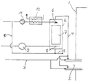
- the invention is described below using an exemplary embodiment in connection with the single drawing in detail explained.
- the drawing shows the schematic structure a device designed according to the invention.
- the illustration shows schematically a boiler 1 with a Burner 2, which is connected to fuel via a fuel line 3, for example heating oil. Also owns the burner 2 an atomizing air supply line 4. Die atomizing air supplied with this serves for atomizing the fuel to form a fuel-air mixture, which is subjected to a combustion process.
- Embodiment is the atomizing air from the blower 9 under pressure and in the heated state in a humidification tower 5 introduced.
- the introduction follows at the bottom of the tower. From an appropriate line 8 the atomizing air is blown upwards.
- a contact body 7 made of a suitable material.
- a liquid supply line opens into the tower 10 shown liquid circuit. Act on the liquid it is water.
- the water is pump 11 fed to a heat exchanger 12 and heated there. The thermal energy To heat the water, the boiler 1 come.
- the water supplied is only partially evaporates. A larger part is collected in the lower one End range of the humidification tower 5 and from there put back into the liquid circuit 10. Alternatively excess water can be drained off, as at 13 shown.
Landscapes
- Engineering & Computer Science (AREA)
- Chemical & Material Sciences (AREA)
- Combustion & Propulsion (AREA)
- Mechanical Engineering (AREA)
- General Engineering & Computer Science (AREA)
Applications Claiming Priority (2)
| Application Number | Priority Date | Filing Date | Title |
|---|---|---|---|
| DE19744867 | 1997-10-10 | ||
| DE19744867A DE19744867A1 (de) | 1997-10-10 | 1997-10-10 | Verfahren und Vorrichtung zum Betreiben eines mit flüssigen oder gasförmigen Kohlenwasserstoffen befeuerten Kessels |
Publications (3)
| Publication Number | Publication Date |
|---|---|
| EP0908676A2 true EP0908676A2 (fr) | 1999-04-14 |
| EP0908676A3 EP0908676A3 (fr) | 1999-05-19 |
| EP0908676B1 EP0908676B1 (fr) | 2003-01-08 |
Family
ID=7845199
Family Applications (1)
| Application Number | Title | Priority Date | Filing Date |
|---|---|---|---|
| EP98118987A Expired - Lifetime EP0908676B1 (fr) | 1997-10-10 | 1998-10-07 | Procédé et dispositif pour la mise en oeuvre d'une chaudière fonctionnant aux hydrocarbures liquides ou gazeux |
Country Status (3)
| Country | Link |
|---|---|
| US (1) | US6210150B1 (fr) |
| EP (1) | EP0908676B1 (fr) |
| DE (2) | DE19744867A1 (fr) |
Families Citing this family (3)
| Publication number | Priority date | Publication date | Assignee | Title |
|---|---|---|---|---|
| US6464492B1 (en) * | 2001-04-26 | 2002-10-15 | John Zink Company, Llc | Methods of utilizing boiler blowdown for reducing NOx |
| CA2430088A1 (fr) | 2003-05-23 | 2004-11-23 | Acs Engineering Technologies Inc. | Methode et appareil de production de vapeur |
| US8858223B1 (en) * | 2009-09-22 | 2014-10-14 | Proe Power Systems, Llc | Glycerin fueled afterburning engine |
Family Cites Families (13)
| Publication number | Priority date | Publication date | Assignee | Title |
|---|---|---|---|---|
| DE15207C (de) * | W. D. DlCKEY in New-York, V. St. A | Neuerungen an Dampfkesselfeuerungen | ||
| US3183864A (en) * | 1962-02-14 | 1965-05-18 | Combustion Eng | Method and system for operating a furnace |
| US3938934A (en) * | 1974-11-08 | 1976-02-17 | Scm Corporation | Fuel economizer process and apparatus |
| US4009984A (en) * | 1976-03-08 | 1977-03-01 | Morrison Charles F | Vapor injection system for fuel combustion |
| US4173450A (en) * | 1976-03-29 | 1979-11-06 | Allied Energy Corporation | Device for injecting air processed to increase its humidity into oil burning furnaces |
| US4089633A (en) * | 1976-03-29 | 1978-05-16 | Barghout Alexander S | Combustion vapor generator |
| US4162140A (en) * | 1977-09-26 | 1979-07-24 | John Zink Company | NOx abatement in burning of gaseous or liquid fuels |
| DE3025851C2 (de) * | 1980-07-08 | 1982-06-03 | Johannes Josef Dr.-Ing. 8000 München Martin | Rostfeuerung |
| US4533314A (en) * | 1983-11-03 | 1985-08-06 | General Electric Company | Method for reducing nitric oxide emissions from a gaseous fuel combustor |
| FR2555711A1 (fr) * | 1983-11-28 | 1985-05-31 | Seccacier | Chaudiere a gaz |
| DE3621314A1 (de) * | 1986-06-25 | 1988-01-07 | Kiesel Geb Rothkegel Vera | Luftwaescher zur befeuchtung und temperierung von luft in klimaanlagen odgl. |
| US5620503A (en) * | 1993-11-04 | 1997-04-15 | Tom Miller, Inc. | Humidifier and method for humidifying air |
| US5832846A (en) * | 1996-01-11 | 1998-11-10 | Public Service Electric And Gas Corporation | Water injection NOx control process and apparatus for cyclone boilers |
-
1997
- 1997-10-10 DE DE19744867A patent/DE19744867A1/de not_active Withdrawn
-
1998
- 1998-10-07 DE DE59806854T patent/DE59806854D1/de not_active Expired - Lifetime
- 1998-10-07 EP EP98118987A patent/EP0908676B1/fr not_active Expired - Lifetime
- 1998-10-07 US US09/168,007 patent/US6210150B1/en not_active Expired - Lifetime
Also Published As
| Publication number | Publication date |
|---|---|
| DE19744867A1 (de) | 1999-04-15 |
| EP0908676B1 (fr) | 2003-01-08 |
| US6210150B1 (en) | 2001-04-03 |
| EP0908676A3 (fr) | 1999-05-19 |
| DE59806854D1 (de) | 2003-02-13 |
Similar Documents
| Publication | Publication Date | Title |
|---|---|---|
| DE69516307T2 (de) | Verfahren zum zuführen von dampf zur einlassluft einer brennkraftmaschine und vorrichtung dazu | |
| DE2402043C3 (de) | Anlage zur Verdampfung und Erwärmung von verflüssigtem Erdgas | |
| DE60006305T2 (de) | Gasturbinensystem | |
| AT399333B (de) | Vorrichtung zur herstellung von schwefelsäure | |
| DE2316116A1 (de) | Verfahren und vorrichtung zur wiedergewinnung von daempfen aus einem luft-dampfgemisch | |
| DE2627150A1 (de) | Kraftstoff-zerstaeubereinheit | |
| DE3404915A1 (de) | Verfahren zur verbrennung wasserhaltiger brennstoffe und anordnung zur durchfuehrung des verfahrens | |
| DE2951557C2 (de) | Verfahren zum Betreiben eines thermischen Stofftrennprozesses mit integrierter Wärmerückführung und Vorrichtung zur Durchführung des Verfahrens | |
| EP0854978B1 (fr) | Moteur a combustion interne stationnaire et procede de fonctionnement correspondant | |
| EP0908676B1 (fr) | Procédé et dispositif pour la mise en oeuvre d'une chaudière fonctionnant aux hydrocarbures liquides ou gazeux | |
| DE2614587A1 (de) | Verfahren zum eindampfen wasserhaltiger fluessigkeiten | |
| DE69624189T2 (de) | Anlage zur Verbrennung von emulgiertem Schweröl | |
| DE19750181C2 (de) | Vorrichtung zur Zuführung von Dampf zur Einlaßluft einer Brennkraftmaschine | |
| DE3731882C1 (en) | Process and plant for exhaust air purification | |
| DE3344089A1 (de) | Vorrichtung fuer heizungsanlagen | |
| DE69804032T2 (de) | Anlage zur Verbrennung von emulgiertem Schweröl | |
| DD244499A5 (de) | Mischeinrichtung fuer unterschiedlich temperierte gasstroeme | |
| DE2825683C3 (de) | Verbrennungsvorrichtung für flüssigen Brennstoff mit einem porösen Körper | |
| EP0020821A1 (fr) | Procédé pour l'utilisation de la chaleur perdue des gaz d'échappement | |
| DE3303475A1 (de) | Verfahren und vorrichtung zur reinigung von rauchgas und ruechgewinnung von abgaswaerme | |
| EP0443645A2 (fr) | Procédé de purification de gaz d'échappement | |
| DE2757783A1 (de) | Verfahren und vorrichtung zur behandlung fluessiger abfaelle | |
| EP0036102A2 (fr) | Dispositif de séchage | |
| DE29808392U1 (de) | Anlage zur Futtermittelherstellung | |
| DE2706037A1 (de) | Verfahren und vorrichtung zur verbrennung von brennstoffen |
Legal Events
| Date | Code | Title | Description |
|---|---|---|---|
| PUAI | Public reference made under article 153(3) epc to a published international application that has entered the european phase |
Free format text: ORIGINAL CODE: 0009012 |
|
| PUAL | Search report despatched |
Free format text: ORIGINAL CODE: 0009013 |
|
| AK | Designated contracting states |
Kind code of ref document: A2 Designated state(s): DE DK FR GB NL SE |
|
| AX | Request for extension of the european patent |
Free format text: AL;LT;LV;MK;RO;SI |
|
| AK | Designated contracting states |
Kind code of ref document: A3 Designated state(s): AT BE CH CY DE DK ES FI FR GB GR IE IT LI LU MC NL PT SE |
|
| AX | Request for extension of the european patent |
Free format text: AL;LT;LV;MK;RO;SI |
|
| 17P | Request for examination filed |
Effective date: 19991021 |
|
| AKX | Designation fees paid |
Free format text: DE DK FR GB NL SE |
|
| 17Q | First examination report despatched |
Effective date: 20010319 |
|
| GRAG | Despatch of communication of intention to grant |
Free format text: ORIGINAL CODE: EPIDOS AGRA |
|
| GRAG | Despatch of communication of intention to grant |
Free format text: ORIGINAL CODE: EPIDOS AGRA |
|
| GRAH | Despatch of communication of intention to grant a patent |
Free format text: ORIGINAL CODE: EPIDOS IGRA |
|
| GRAH | Despatch of communication of intention to grant a patent |
Free format text: ORIGINAL CODE: EPIDOS IGRA |
|
| GRAA | (expected) grant |
Free format text: ORIGINAL CODE: 0009210 |
|
| AK | Designated contracting states |
Kind code of ref document: B1 Designated state(s): DE DK FR GB NL SE |
|
| REG | Reference to a national code |
Ref country code: GB Ref legal event code: FG4D Free format text: NOT ENGLISH |
|
| REF | Corresponds to: |
Ref document number: 59806854 Country of ref document: DE Date of ref document: 20030213 Kind code of ref document: P |
|
| PG25 | Lapsed in a contracting state [announced via postgrant information from national office to epo] |
Ref country code: SE Free format text: LAPSE BECAUSE OF FAILURE TO SUBMIT A TRANSLATION OF THE DESCRIPTION OR TO PAY THE FEE WITHIN THE PRESCRIBED TIME-LIMIT Effective date: 20030408 Ref country code: DK Free format text: LAPSE BECAUSE OF FAILURE TO SUBMIT A TRANSLATION OF THE DESCRIPTION OR TO PAY THE FEE WITHIN THE PRESCRIBED TIME-LIMIT Effective date: 20030408 |
|
| GBT | Gb: translation of ep patent filed (gb section 77(6)(a)/1977) |
Effective date: 20030512 |
|
| ET | Fr: translation filed | ||
| PLBE | No opposition filed within time limit |
Free format text: ORIGINAL CODE: 0009261 |
|
| STAA | Information on the status of an ep patent application or granted ep patent |
Free format text: STATUS: NO OPPOSITION FILED WITHIN TIME LIMIT |
|
| 26N | No opposition filed |
Effective date: 20031009 |
|
| PGFP | Annual fee paid to national office [announced via postgrant information from national office to epo] |
Ref country code: DE Payment date: 20121029 Year of fee payment: 15 Ref country code: FR Payment date: 20121126 Year of fee payment: 15 |
|
| PGFP | Annual fee paid to national office [announced via postgrant information from national office to epo] |
Ref country code: GB Payment date: 20121024 Year of fee payment: 15 |
|
| PGFP | Annual fee paid to national office [announced via postgrant information from national office to epo] |
Ref country code: NL Payment date: 20121023 Year of fee payment: 15 |
|
| REG | Reference to a national code |
Ref country code: NL Ref legal event code: V1 Effective date: 20140501 |
|
| GBPC | Gb: european patent ceased through non-payment of renewal fee |
Effective date: 20131007 |
|
| REG | Reference to a national code |
Ref country code: DE Ref legal event code: R119 Ref document number: 59806854 Country of ref document: DE Effective date: 20140501 |
|
| PG25 | Lapsed in a contracting state [announced via postgrant information from national office to epo] |
Ref country code: GB Free format text: LAPSE BECAUSE OF NON-PAYMENT OF DUE FEES Effective date: 20131007 |
|
| REG | Reference to a national code |
Ref country code: FR Ref legal event code: ST Effective date: 20140630 |
|
| PG25 | Lapsed in a contracting state [announced via postgrant information from national office to epo] |
Ref country code: FR Free format text: LAPSE BECAUSE OF NON-PAYMENT OF DUE FEES Effective date: 20131031 Ref country code: NL Free format text: LAPSE BECAUSE OF NON-PAYMENT OF DUE FEES Effective date: 20140501 Ref country code: DE Free format text: LAPSE BECAUSE OF NON-PAYMENT OF DUE FEES Effective date: 20140501 |