EP0908685A2 - Réchauffeur de fluide - Google Patents
Réchauffeur de fluide Download PDFInfo
- Publication number
- EP0908685A2 EP0908685A2 EP98119017A EP98119017A EP0908685A2 EP 0908685 A2 EP0908685 A2 EP 0908685A2 EP 98119017 A EP98119017 A EP 98119017A EP 98119017 A EP98119017 A EP 98119017A EP 0908685 A2 EP0908685 A2 EP 0908685A2
- Authority
- EP
- European Patent Office
- Prior art keywords
- liquid
- diving bell
- hollow body
- combustion
- wall
- Prior art date
- Legal status (The legal status is an assumption and is not a legal conclusion. Google has not performed a legal analysis and makes no representation as to the accuracy of the status listed.)
- Withdrawn
Links
- 239000012530 fluid Substances 0.000 title description 3
- 239000007788 liquid Substances 0.000 claims abstract description 56
- 230000009189 diving Effects 0.000 claims abstract description 48
- 238000002485 combustion reaction Methods 0.000 claims abstract description 22
- 239000000446 fuel Substances 0.000 claims abstract description 4
- 239000000567 combustion gas Substances 0.000 claims description 32
- 238000010438 heat treatment Methods 0.000 claims description 21
- 239000007789 gas Substances 0.000 claims description 15
- 238000013517 stratification Methods 0.000 claims description 8
- 230000009969 flowable effect Effects 0.000 claims 1
- XLYOFNOQVPJJNP-UHFFFAOYSA-N water Substances O XLYOFNOQVPJJNP-UHFFFAOYSA-N 0.000 abstract description 14
- 239000003546 flue gas Substances 0.000 abstract description 5
- 239000013529 heat transfer fluid Substances 0.000 description 16
- 239000003651 drinking water Substances 0.000 description 2
- 235000020188 drinking water Nutrition 0.000 description 2
- 238000007654 immersion Methods 0.000 description 2
- 238000000034 method Methods 0.000 description 2
- 230000002093 peripheral effect Effects 0.000 description 2
- UGFAIRIUMAVXCW-UHFFFAOYSA-N Carbon monoxide Chemical compound [O+]#[C-] UGFAIRIUMAVXCW-UHFFFAOYSA-N 0.000 description 1
- 238000004891 communication Methods 0.000 description 1
- 239000003344 environmental pollutant Substances 0.000 description 1
- 238000001704 evaporation Methods 0.000 description 1
- 230000008020 evaporation Effects 0.000 description 1
- 230000012447 hatching Effects 0.000 description 1
- 238000005338 heat storage Methods 0.000 description 1
- 231100000719 pollutant Toxicity 0.000 description 1
- 238000005201 scrubbing Methods 0.000 description 1
- 239000000126 substance Substances 0.000 description 1
- 238000012549 training Methods 0.000 description 1
- 238000012546 transfer Methods 0.000 description 1
- 238000005406 washing Methods 0.000 description 1
Images
Classifications
-
- F—MECHANICAL ENGINEERING; LIGHTING; HEATING; WEAPONS; BLASTING
- F24—HEATING; RANGES; VENTILATING
- F24H—FLUID HEATERS, e.g. WATER OR AIR HEATERS, HAVING HEAT-GENERATING MEANS, e.g. HEAT PUMPS, IN GENERAL
- F24H1/00—Water heaters, e.g. boilers, continuous-flow heaters or water-storage heaters
- F24H1/10—Continuous-flow heaters, i.e. heaters in which heat is generated only while the water is flowing, e.g. with direct contact of the water with the heating medium
- F24H1/107—Continuous-flow heaters, i.e. heaters in which heat is generated only while the water is flowing, e.g. with direct contact of the water with the heating medium using fluid fuel
Definitions
- the invention relates to a device for heating a liquid the preamble of claim 1.
- a device of this type is already known from US-A-2 233 675. These The device described serves to heat liquids of the most varied types Kind, also with the aim of their evaporation. What is special about the device is that the combustion gases from a gas burner into one Liquid submersible diving bell are guided on its outer circumference is provided with a perforated plate through which the combustion gases passed through and distributed directly in the liquid. It will already pointed out in this old American patent specification that on practically the entire calorific value of the Fuel can be transferred to the liquid.
- the gas burner is at the subject of the American patent within the diving bell arranged.
- the diving bell with its for the distribution of the combustion gases provided perforated sheet in the subject of the US patent free in the heating volume of liquid, namely at the bottom of the liquid container.
- the perforated plate is on its outer circumference with an annular apron provided, which forces the combustion gases upwards through the perforated plate to emerge and not to flow past its outer edge. Because the diving bell with the perforated plate and its peripheral apron on the bottom of the container stands, the apron is on its lower edge with wavy recesses for fluid communication and fluid pressure equalization between the rooms inside and outside the diving bell.
- a large volume of liquid storage has the advantage that it is vertical in the absence of turbulent flow Forms temperature stratification, which can be used to generate thermal energy to supply this stratification in suitable temperature ranges and to decrease.
- boilers in which also directly with the Combustion gases from a burner are a heat transfer fluid, as a rule Water, is heated without pressure, with a high efficiency being achieved by also the water vapor from the combustion gases is still directly in the Heat transfer fluid is condensed.
- the well-known boilers work with a relatively small volume of a heat transfer fluid and are designed so that the combustion gases as possible from below flow through the entire column of heat transfer fluid in order to limited to the relatively small volume of the heat transfer fluid, a high one To achieve heat utilization.
- Such boilers are for example in EP-A-0 466 748 and DE-C-195 09 461.
- the invention has for its object the liquid heating system from US-A-2 233 675 for drinking water and process water heating as well make the space heating usable.
- Exhaust gas heat exchanger to be provided with the liquid relatively lower Temperature is supplied from the lowest layers of the storage volume. The thus warmed up liquid is then in a suitable place in the temperature stratification of the memory returned. This way the rest Exhaust gas heat is optimally used in the device itself.
- the in the heat transfer fluid stored heat energy for external use heat exchanger to be provided within the device.
- it is more advantageous to use external heat exchanger because external heat exchanger with special flow conditions and very high heat transfer to let. So it makes sense in the context of the present invention, hot water for the bathroom, for example, in a highly sensitive plate heat exchanger to generate the externally with heat transfer fluid from the invention Device is powered by a power-controlled charge pump. Because hot water generally requires the highest heat level in household consumption, the heat transfer fluid is expedient for such a heat exchanger from the uppermost layering area of the device according to the invention withdrawn and the return in the lowest area of the device fed again.
- a solar heating system is connected to the device according to the invention, this should be designed so that it is at water temperatures below about 60 ° C. switches off under which condition the one heated in the solar heat exchanger Heat transfer fluid then immediately the uppermost area of the invention Device can be supplied.
- connections in the container wall are those of the invention to provide the device at the appropriate height.
- Temperature is automatically fed to the correct temperature layer in the container, so that flow vortices are largely avoided by the return line.
- the device according to the invention is also expediently inside of the container also provided with suitable baffles that meet the target serve unnecessary currents disturbing the temperature stratification within the To avoid the container.
- the diving bell to which the combustion gases are fed, dives in the frame the invention preferably from above only up to a third of the maximum Liquid level into the liquid.
- the immersion depth of the bell based on the liquid level, also be much less, for example less than a quarter of the Liquid column.
- a combustion chamber with a burner outside the diving bell to arrange and only the combustion gases in the diving bell introduce.
- the combustion chamber is preferably located within the Diving bell, the burner expediently through the top wall the diving bell extends into the combustion chamber.
- the diving bell itself forms the combustion chamber. In this case, kick the combustion gases into the liquid over the bottom of the diving bell out.
- This arrangement has the disadvantage that when the burner is switched off and switched off combustion air the liquid fills the diving bell from below and a gas space is only generated again by the combustion air blower before the burner can be switched on again.
- the embodiment of the invention should be the case that the low immersion depth
- the diving bell in the liquid is insufficient to hold the entire under it Arrange combustion chamber. It can therefore have a different training special guidance for the combustion gases may be required.
- Such an expedient embodiment is, for example, that the Combustion chamber is formed by a hollow body, the bottom by a Beden is closed and open at the top, and from below into the diving bell protrudes, but it itself over the lower edge of the diving bell can dip into the liquid, the more volume for the To provide the combustion chamber and the burner.
- a combustion gas guide tube provided by the top wall of the diving bell protrudes into the combustion chamber, but not to on their floor.
- the combustion gases then flow out of the lower area the combustion chamber under the lower edge of the combustion gas pipe into a gap between this guide tube and the outer wall of the hollow body of the combustion chamber and flow in this space upwards and then over the top edge of the hollow body into the space between the outer wall of the hollow body and the diving bell to flow downwards again in this space.
- the exit cross section the diving bell is that of this ring-like space between the outer wall of the hollow body of the combustion chamber and the diving bell.
- the combustion gases arrive from the lower edge of the diving bell then under the perforated plate surrounding the diving bell and flow through it into the liquid volume above the perforated plate.
- the outer circumference ends the perforated plate freely in the liquid.
- the perforated plate is on its outer circumference provided with a downwardly projecting collar, which prevents the combustion gases past the peripheral edge of the perforated plate upwards leak the liquid.
- the liquid volume of the device according to the invention can, for example are between 600 and 1200 liters.
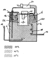
- FIG. 1 An exemplary embodiment of a Device for heating a heat transfer fluid shown.
- the simplified one Sectional drawing shows a container 2 with three liquid layers 4, the different temperatures according to that applied below the container 2 Show hatching fields.
- a diving bell 6 arranged on which a burner 10 is attached.
- the burner 10 is from surrounded a hollow body 20 closed at the bottom, which has a combustion chamber 8 forms.
- a perforated plate 14 is provided.
- an annular channel with an outlet cross section 12 through which the Combustion gas is led into the liquid 4 below the perforated plate 14.
- Within the hollow body 20 is a guide tube 22 for the combustion gas arranged so that the combustion gas from the burner 10 is initially down and then between the guide tube 22 and the hollow body 20 upwards and finally can flow down between hollow body 20 and diving bell 6.
- the container 2 has connections 16 for the supply and discharge of the liquid 4 fitted. To keep liquid flows of different return temperatures in Being able to introduce different temperature ranges is also a So-called stratified loader 18 is provided. Outside of the container 2 is another Exhaust gas heat exchanger 24 arranged, which expediently with liquid 4th from the lowest temperature range to the exhaust heat to be able to take full advantage of it.
Landscapes
- Engineering & Computer Science (AREA)
- Physics & Mathematics (AREA)
- Thermal Sciences (AREA)
- Chemical & Material Sciences (AREA)
- Combustion & Propulsion (AREA)
- Mechanical Engineering (AREA)
- General Engineering & Computer Science (AREA)
- Heat-Pump Type And Storage Water Heaters (AREA)
Applications Claiming Priority (2)
| Application Number | Priority Date | Filing Date | Title |
|---|---|---|---|
| DE1997144478 DE19744478C1 (de) | 1997-10-09 | 1997-10-09 | Vorrichtung zum Erwärmen einer Flüssigkeit |
| DE19744478 | 1997-10-09 |
Publications (2)
| Publication Number | Publication Date |
|---|---|
| EP0908685A2 true EP0908685A2 (fr) | 1999-04-14 |
| EP0908685A3 EP0908685A3 (fr) | 2001-05-09 |
Family
ID=7844960
Family Applications (1)
| Application Number | Title | Priority Date | Filing Date |
|---|---|---|---|
| EP98119017A Withdrawn EP0908685A3 (fr) | 1997-10-09 | 1998-10-08 | Réchauffeur de fluide |
Country Status (2)
| Country | Link |
|---|---|
| EP (1) | EP0908685A3 (fr) |
| DE (1) | DE19744478C1 (fr) |
Citations (3)
| Publication number | Priority date | Publication date | Assignee | Title |
|---|---|---|---|---|
| US2233675A (en) | 1936-11-02 | 1941-03-04 | Firm Silesia Ver Chemischer Fa | Device for heating liquids |
| EP0466748A1 (fr) | 1989-04-05 | 1992-01-22 | Herwisolar Gmbh Forschung Und | Chaudiere en plastique avec epuration integree des gaz d'echappement. |
| DE19509461C1 (de) | 1995-03-20 | 1996-05-15 | Inst Wirtschaftliche Oelheizun | Heizkessel für flüssige oder gasförmige Brennstoffe |
Family Cites Families (6)
| Publication number | Priority date | Publication date | Assignee | Title |
|---|---|---|---|---|
| DE2130770A1 (de) * | 1971-06-22 | 1972-12-28 | Linde Robert Von Dipl Ing | Heizanlage fuer Schwimmbaeder |
| DE2722882A1 (de) * | 1977-05-20 | 1978-11-23 | Koelbel Gert Friedrich | Gymnastikgeraet fuer zug- und druckuebungen |
| JPS5589644A (en) * | 1978-12-25 | 1980-07-07 | Hiroki Sano | Hot air heater for liquid |
| DE3570913D1 (en) * | 1984-02-08 | 1989-07-13 | Pulmatec Holding Inc | Process and apparatus for heating a liquid in a non-polluting way |
| DE3640281A1 (de) * | 1986-11-25 | 1988-06-01 | Weiss Hans Joachim | Heizvorrichtung, insbesondere fuer fluessige oder gasfoermige brennstoffe |
| DE9310503U1 (de) * | 1993-07-14 | 1994-02-17 | Herle, Alexander P., 76297 Stutensee | Einrichtung für die Beheizung des Zulaufs und die Verbesserung der Leistung anaerober Anlagen |
-
1997
- 1997-10-09 DE DE1997144478 patent/DE19744478C1/de not_active Expired - Fee Related
-
1998
- 1998-10-08 EP EP98119017A patent/EP0908685A3/fr not_active Withdrawn
Patent Citations (3)
| Publication number | Priority date | Publication date | Assignee | Title |
|---|---|---|---|---|
| US2233675A (en) | 1936-11-02 | 1941-03-04 | Firm Silesia Ver Chemischer Fa | Device for heating liquids |
| EP0466748A1 (fr) | 1989-04-05 | 1992-01-22 | Herwisolar Gmbh Forschung Und | Chaudiere en plastique avec epuration integree des gaz d'echappement. |
| DE19509461C1 (de) | 1995-03-20 | 1996-05-15 | Inst Wirtschaftliche Oelheizun | Heizkessel für flüssige oder gasförmige Brennstoffe |
Also Published As
| Publication number | Publication date |
|---|---|
| EP0908685A3 (fr) | 2001-05-09 |
| DE19744478C1 (de) | 1999-06-17 |
Similar Documents
| Publication | Publication Date | Title |
|---|---|---|
| DE4417138C2 (de) | Warmwasserschichtspeicher | |
| DE2846120C2 (de) | Wasserspeichererhitzer | |
| CH616499A5 (en) | Central heating system with a boiler and an additional heat exchanger for preheating the medium flowing back to the boiler | |
| DE19704986B4 (de) | Schichtenspeicheranordnung | |
| DE4443715C2 (de) | Warmwasserbereiter | |
| EP0924471A2 (fr) | Accumulateur de chaleur | |
| EP0908685A2 (fr) | Réchauffeur de fluide | |
| DE3238603C2 (fr) | ||
| DE19509461C1 (de) | Heizkessel für flüssige oder gasförmige Brennstoffe | |
| DE10017640B4 (de) | Wärmespeicher für eine Warmwasserheizung und zur Aufbereitung von Hygienewarmwasser | |
| DE102011010669B4 (de) | Pufferspeicher | |
| EP0609853A1 (fr) | Générateur de chaleur pour la production d'eau chaude et pour le chauffage | |
| DE3046454A1 (de) | Heizungskessel | |
| DE69918129T2 (de) | Kessel | |
| DE60106247T2 (de) | Wasserheizer mit vorheizer im brennraum | |
| DE29813784U1 (de) | Warmwasserspeicher | |
| AT411393B (de) | Trinkwasserspeicher | |
| DE102004048884B4 (de) | Wärmeübertrager | |
| DE10323713A1 (de) | Wassererwärmer | |
| DE10219250B3 (de) | Speicherbehälter | |
| EP0376297B1 (fr) | Accumulateur d'eau chaude | |
| DE2608412A1 (de) | Kombinierte filter- und heizvorrichtung fuer fluessigkeiten, insbesondere fuer ein schwimmbecken | |
| EP0319009B1 (fr) | Ballon d'eau chaude | |
| EP0320678A2 (fr) | Appareil pour préparation et accumulation d'eau sanitaire | |
| DE8712358U1 (de) | Heizkessel |
Legal Events
| Date | Code | Title | Description |
|---|---|---|---|
| PUAI | Public reference made under article 153(3) epc to a published international application that has entered the european phase |
Free format text: ORIGINAL CODE: 0009012 |
|
| AK | Designated contracting states |
Kind code of ref document: A2 Designated state(s): AT BE CH CY DE DK ES FI FR GB GR IE IT LI LU MC NL PT SE |
|
| AX | Request for extension of the european patent |
Free format text: AL;LT;LV;MK;RO;SI |
|
| PUAL | Search report despatched |
Free format text: ORIGINAL CODE: 0009013 |
|
| AK | Designated contracting states |
Kind code of ref document: A3 Designated state(s): AT BE CH CY DE DK ES FI FR GB GR IE IT LI LU MC NL PT SE |
|
| AX | Request for extension of the european patent |
Free format text: AL;LT;LV;MK;RO;SI |
|
| AKX | Designation fees paid | ||
| REG | Reference to a national code |
Ref country code: DE Ref legal event code: 8566 |
|
| STAA | Information on the status of an ep patent application or granted ep patent |
Free format text: STATUS: THE APPLICATION IS DEEMED TO BE WITHDRAWN |
|
| 18D | Application deemed to be withdrawn |
Effective date: 20011110 |