EP0908735A2 - Procédé pour déterminer la fréquence d'un signal - Google Patents
Procédé pour déterminer la fréquence d'un signal Download PDFInfo
- Publication number
- EP0908735A2 EP0908735A2 EP98118893A EP98118893A EP0908735A2 EP 0908735 A2 EP0908735 A2 EP 0908735A2 EP 98118893 A EP98118893 A EP 98118893A EP 98118893 A EP98118893 A EP 98118893A EP 0908735 A2 EP0908735 A2 EP 0908735A2
- Authority
- EP
- European Patent Office
- Prior art keywords
- frequency
- signal
- transformation
- fft
- line
- Prior art date
- Legal status (The legal status is an assumption and is not a legal conclusion. Google has not performed a legal analysis and makes no representation as to the accuracy of the status listed.)
- Granted
Links
Images


Classifications
-
- G—PHYSICS
- G01—MEASURING; TESTING
- G01R—MEASURING ELECTRIC VARIABLES; MEASURING MAGNETIC VARIABLES
- G01R23/00—Arrangements for measuring frequencies; Arrangements for analysing frequency spectra
- G01R23/02—Arrangements for measuring frequency, e.g. pulse repetition rate; Arrangements for measuring period of current or voltage
-
- G—PHYSICS
- G01—MEASURING; TESTING
- G01R—MEASURING ELECTRIC VARIABLES; MEASURING MAGNETIC VARIABLES
- G01R23/00—Arrangements for measuring frequencies; Arrangements for analysing frequency spectra
- G01R23/16—Spectrum analysis; Fourier analysis
- G01R23/165—Spectrum analysis; Fourier analysis using filters
- G01R23/167—Spectrum analysis; Fourier analysis using filters with digital filters
Definitions
- the invention is based on a method for determination the frequency of a signal according to the preamble of the claim 1.
- a digitized signal present in the time domain at least to determine a frequency, for example in one modulated signal the frequencies of the underlying Individual signals.
- the digitized Signal transformed into the frequency domain for example by means of a Fourier transform known per se or the Fast Fourier Transform (FFT).
- FFT Fast Fourier Transform
- a line spectrum corresponding to the signal then arises, that can be specified in a manner known per se Characteristics can be evaluated.
- at a modulated signal determines the frequency of the carrier signal , for example by determining the Position of at least one spectral line on the frequency axis and / or by measuring (frequency) distances from specifiable spectral lines.
- the invention is therefore based on the object of a generic To improve the process so that a predeterminable precise frequency measurement is possible.
- a first advantage of the invention is that the invention The process is largely independent of intentional and / or unintentional disturbances and environmental conditions, for example, another layered Signal that is almost identical to the signal to be evaluated.
- a second advantage is that a predeterminable accuracy Frequency determination is also possible with pulsed signals.
- a third advantage is that the invention also is applicable to high or very high frequency signals.
- a fourth advantage is that it has high aging resistance an arrangement operated according to the method is achievable. An advantageously arises good reproducibility of the measurement results, in particular the so-called drifting is avoided.
- an analog electrical signal present in the time domain is first digitized in a manner known per se, for example by means of an analog / digital converter, so that so-called sampled values are produced.
- sampled values are produced in the case of high-frequency or extremely high-frequency signals.
- the analog signal present in this IF range is then digitized.
- Such an implementation is currently common in radar technology, for example.
- a predeterminable time periodic sequence of samples for example, a maximum of about 2000, is then by a known time-continuous complex digital filtering, preferably a known complex broadband FFT (F AST F ourier- T ransformation), in the frequency domain implemented.
- FFT complex broadband FFT
- the temporal length (time duration) of such a sequence of samples is also called the FFT interval.
- FFT complex broadband FFT
- amplitude spectrum in an FFT interval for example, the (frequency) line with the greatest amplitude can first be selected and then its position on the frequency axis can be determined.
- a weighting for example averaging for the frequency to be determined.
- T FFT means the time length of the FFT interval
- a phase value ⁇ 0 to committee n belongs to each result vector p0 to pn, that is to say to the result vector p0 the phase value ⁇ 0 , to the result vector p1 the phase value ⁇ 1 and so on.
- phase differences ⁇ n (n-1) to ⁇ n1 and the associated time differences ⁇ t n (n-1) to ⁇ t n1 formed in this way are also added up separately and also stored, preferably to the already existing phase and time sums.
- the frequency F is then determined from an evaluation according to formula (2).
- An evaluation described above with reference to FIGS. 2a to 2c is advantageously technically simple and can be carried out within a short time by means of at least one so-called shift register, which has a length n, that is, it is initially possible to sequentially (serially) the result vectors p0 to pn belonging phase values ⁇ 1 to ⁇ n are read in and then, by means of a parallel reading process, the phase differences ⁇ 01 to ⁇ n1 are formed and further processed in the manner described.
- the frequency F is then determined as described with reference to FIGS. 2a to 2c.
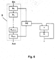
- This method according to FIG. 3 has the advantage over that according to FIGS. 2a to 2c that only a shift register S (FIG. 6) with an input on and an output off and the length n / 2 is required. From this, only the first and the last phase value, ⁇ 0 and ⁇ n / 2 in Fig. 6, have to be read out, since they have the distance n / 2.
- the method described with reference to FIG. 3 is special then advantageously applicable if the frequency F at a pulsed high-frequency coherent analog signal determined shall be.
- Such an analog signal that from there is a sequence of so-called bursts for example, in that a mono-frequency high-frequency coherent carrier signal by means of a square wave signal, with almost any duty cycle, completely is modulated.
- Such an analog RF signal is used, for example used as a transmission signal in a pulse radar.
- the frequency of the carrier signal is to be determined in the case of such a pulsed analog signal for at least one pulse, it is expedient to carry out an evaluation according to FIG.
- These parameters to be selected depend on the pulse duration, the frequency of the carrier signal and the desired accuracy for the frequency F (formula (2)). It can be seen that under these conditions a single pulse is in principle advantageously sufficient to determine the frequency F of the carrier signal.
- the pulse duration is relatively short and the frequency determination is nevertheless to be carried out with a predeterminable high accuracy, it is advantageously possible to carry out an evaluation to determine the frequency F, which extends over at least two coherent pulses.
- the pulse pause between the pulses can be of almost any length.
- the frequency F is then also determined as described with reference to FIG. 3.
- Fig.5 shows a development of the invention, for the Determination of the frequency F with a strongly disturbed analog Signal (signal mixture) is suitable.
- a digital spectral is created selective signal that consists of a sequence of filtered complex result vectors (scan vectors).
- sequence of samples processed in this way now contains one Sequence of complex vectors, which is an (optional) frequency filtered Represent the image of the analog RF signal.
- This sequence of samples can be based on one of the following of the method described in FIGS. 1 to 4 be, preferably according to a method according to Fig. 3.
- This method has advantages especially when using pulses or RF input signals "cut" or relatively short are, that is only over a maximum length of time two FFT intervals go.
- an accuracy (rms) can be achieved, for example, for a pulsed RF signal (for example a pulsed carrier signal with a carrier frequency of 0.2 GHz) that is sampled with a sampling frequency of approximately 1 GHz.
- a signal to noise ratio of 0 dB is used as the basis for the analog input signal and a 64-point FFT is used, that is to say an FFT interval contains 64 samples.
- the invention has a wide scope of electrical engineering and / or measuring technology for determination a frequency can be used, for example in the determination the angle of incidence of an electromagnetic wave, the frequency associated with the wave being known got to.
- Such a procedure is filed on the same day German patent application with the official German Case number DE - ......... (internal file number: UL 97/16).
Landscapes
- Physics & Mathematics (AREA)
- General Physics & Mathematics (AREA)
- Mathematical Physics (AREA)
- Measuring Frequencies, Analyzing Spectra (AREA)
- Stabilization Of Oscillater, Synchronisation, Frequency Synthesizers (AREA)
- Radar Systems Or Details Thereof (AREA)
Applications Claiming Priority (2)
| Application Number | Priority Date | Filing Date | Title |
|---|---|---|---|
| DE19744691A DE19744691A1 (de) | 1997-10-10 | 1997-10-10 | Verfahren zur Bestimmung der Frequenz eines Signals |
| DE19744691 | 1997-10-10 |
Publications (3)
| Publication Number | Publication Date |
|---|---|
| EP0908735A2 true EP0908735A2 (fr) | 1999-04-14 |
| EP0908735A3 EP0908735A3 (fr) | 2001-09-12 |
| EP0908735B1 EP0908735B1 (fr) | 2005-02-16 |
Family
ID=7845091
Family Applications (1)
| Application Number | Title | Priority Date | Filing Date |
|---|---|---|---|
| EP98118893A Expired - Lifetime EP0908735B1 (fr) | 1997-10-10 | 1998-10-06 | Procédé pour déterminer la fréquence d'un signal |
Country Status (4)
| Country | Link |
|---|---|
| US (1) | US6351505B1 (fr) |
| EP (1) | EP0908735B1 (fr) |
| AT (1) | ATE289417T1 (fr) |
| DE (2) | DE19744691A1 (fr) |
Cited By (2)
| Publication number | Priority date | Publication date | Assignee | Title |
|---|---|---|---|---|
| DE10309262A1 (de) * | 2003-03-03 | 2004-09-23 | Rohde & Schwarz Gmbh & Co. Kg | Verfahren und Vorrichtung zum Schätzen der Frequenz und/oder der Phase einer digitalen Signalfolge |
| CN112986675A (zh) * | 2021-01-28 | 2021-06-18 | 苏州海鹏科技有限公司 | 一种频率变化率的检测方法 |
Families Citing this family (5)
| Publication number | Priority date | Publication date | Assignee | Title |
|---|---|---|---|---|
| DE19810695A1 (de) | 1998-03-12 | 1999-09-16 | Daimler Benz Aerospace Ag | Verfahren zur Detektion eines gepulsten Nutzsignals |
| US20070073797A1 (en) * | 2005-09-29 | 2007-03-29 | Lockheed Martin Corporation | Recursive method for solving the inexact greatest common divisor problem |
| RU2325028C1 (ru) * | 2006-10-17 | 2008-05-20 | Владимир Яковлевич Бараш | Способ преобразования временных сигналов и их параметров |
| CN105467209B (zh) * | 2015-12-02 | 2018-06-29 | 国网四川省电力公司资阳供电公司 | 一种新的金属氧化物避雷器泄漏电流分析方法 |
| CN106970264B (zh) * | 2017-03-02 | 2020-02-21 | 浙江大学 | 一种考虑电网频率变化率的改进相位差校正法 |
Family Cites Families (8)
| Publication number | Priority date | Publication date | Assignee | Title |
|---|---|---|---|---|
| SU873145A2 (ru) * | 1979-12-03 | 1981-10-15 | Предприятие П/Я Г-4173 | Цифровой панорамный измеритель частоты |
| JP2808954B2 (ja) * | 1991-11-13 | 1998-10-08 | 国際電信電話株式会社 | 無変調信号検出及び周波数引き込み装置 |
| US5323391A (en) * | 1992-10-26 | 1994-06-21 | Motorola, Inc. | Multi-channel digital transmitter and receiver |
| US5629870A (en) * | 1994-05-31 | 1997-05-13 | Siemens Energy & Automation, Inc. | Method and apparatus for predicting electric induction machine failure during operation |
| US5499391A (en) * | 1994-06-30 | 1996-03-12 | The United States Of America As Represented By The Secretary Of The Air Force | Digital channelized IFM receiver |
| US5657026A (en) * | 1996-01-26 | 1997-08-12 | Electronic Tracking Systems, Inc. | Beacon signal receiving system |
| US6229856B1 (en) * | 1997-04-14 | 2001-05-08 | Masimo Corporation | Method and apparatus for demodulating signals in a pulse oximetry system |
| US5939887A (en) * | 1997-09-05 | 1999-08-17 | Tektronix, Inc. | Method for measuring spectral energy interference in a cable transmission system |
-
1997
- 1997-10-10 DE DE19744691A patent/DE19744691A1/de not_active Withdrawn
-
1998
- 1998-10-06 EP EP98118893A patent/EP0908735B1/fr not_active Expired - Lifetime
- 1998-10-06 DE DE59812574T patent/DE59812574D1/de not_active Expired - Lifetime
- 1998-10-06 AT AT98118893T patent/ATE289417T1/de not_active IP Right Cessation
- 1998-10-13 US US09/170,200 patent/US6351505B1/en not_active Expired - Lifetime
Cited By (3)
| Publication number | Priority date | Publication date | Assignee | Title |
|---|---|---|---|---|
| DE10309262A1 (de) * | 2003-03-03 | 2004-09-23 | Rohde & Schwarz Gmbh & Co. Kg | Verfahren und Vorrichtung zum Schätzen der Frequenz und/oder der Phase einer digitalen Signalfolge |
| DE10309262B4 (de) * | 2003-03-03 | 2007-08-23 | Rohde & Schwarz Gmbh & Co. Kg | Verfahren zum Schätzen der Frequenz und/oder der Phase einer digitalen Signalfolge |
| CN112986675A (zh) * | 2021-01-28 | 2021-06-18 | 苏州海鹏科技有限公司 | 一种频率变化率的检测方法 |
Also Published As
| Publication number | Publication date |
|---|---|
| EP0908735A3 (fr) | 2001-09-12 |
| DE19744691A1 (de) | 1999-04-15 |
| DE59812574D1 (de) | 2005-03-24 |
| ATE289417T1 (de) | 2005-03-15 |
| EP0908735B1 (fr) | 2005-02-16 |
| US6351505B1 (en) | 2002-02-26 |
Similar Documents
| Publication | Publication Date | Title |
|---|---|---|
| EP2057480B1 (fr) | Système radar destiné au balayage de l'environnement avec compensation de signaux parasites | |
| DE19933754B4 (de) | Verfahren und Vorrichtung zur Hochfrequenzspektralanalyse | |
| DE69737354T2 (de) | Verfahren zur störungsunterdrückung in einem fmcw-radar | |
| DE3787015T2 (de) | Im frequenzbereich wirkendes impulsraffungsradargerät zur störechobeseitigung. | |
| DE3789830T3 (de) | Radargerät zur Messung der Entfernung zu einer Oberfläche. | |
| DE19512904C2 (de) | Verfahren zur Bestimmung der Zwischenfrequenzenabweichung bei Frequenz-Puls-Radarsystemen | |
| DE102008014918A1 (de) | Verfahren zum Erfassen einer Interferenz in einem Radarsystem und Radar, das das gleiche verwendet | |
| DE69120169T2 (de) | Beschleunigungskompensation unter Verwendung von einem Adaptivfilter | |
| DE102015107419A1 (de) | Radarvorrichtung | |
| DE3112112C1 (de) | Pruefvorrichtung fuer ein Radargeraet mit synthetischer Apertur | |
| EP0128543A1 (fr) | Dispositif de radar Doppler à impulsions à fréquence de répétition d'impulsions variable | |
| EP0908735B1 (fr) | Procédé pour déterminer la fréquence d'un signal | |
| DE19750742A1 (de) | Verfahren zur Detektion eines Zieles mittels einer HPRF-Radaranlage | |
| WO2019242794A1 (fr) | Dispositif radar et procédé de fonctionnement d'un dispositif radar | |
| DE2133497A1 (de) | Verfahren und anordnung zur radarenternungsmessung | |
| EP0047477B1 (fr) | Radar Doppler à impulsion du type à élimination d'échos fixes utilisant un circuit à filtres récursifs | |
| DE102022210964B4 (de) | Ein verfahren zum bestimmen einer nichtlinearitätscharakteristik eines empfängerpfads und eine hf-vorrichtung | |
| DE69005500T2 (de) | Messung der Sende-Empfangsstabilität in einem Radargerät. | |
| EP0980151A1 (fr) | Procédé de mesure d'atténuation dans des lignes de transmission numérique | |
| EP0422479B1 (fr) | Appareil de compression d'impulsions | |
| EP0703465B1 (fr) | Procédé pour radar à impulsions | |
| DE2061989C3 (de) | Puls-Koharenzdopplerradargerat | |
| EP1102089B1 (fr) | Méthode et dispositif pour déterminer la distance à un objet employant un signal électromagnétique à impulsions | |
| DE2535463C1 (de) | Pulsradargeraet mit phasensprungcodierten Sendeimpulsen und empfangsseitiger Pulskompression nach kohaerenter Demodulation | |
| DE1160653B (de) | Einrichtung zur Impulslaufzeit-Entfernungsmessung |
Legal Events
| Date | Code | Title | Description |
|---|---|---|---|
| PUAI | Public reference made under article 153(3) epc to a published international application that has entered the european phase |
Free format text: ORIGINAL CODE: 0009012 |
|
| AK | Designated contracting states |
Kind code of ref document: A2 Designated state(s): AT BE CH CY DE DK ES FI FR GB GR IE IT LI LU MC NL PT SE Kind code of ref document: A2 Designated state(s): AT CH DE FR GB LI |
|
| AX | Request for extension of the european patent |
Free format text: AL;LT;LV;MK;RO;SI |
|
| RAP1 | Party data changed (applicant data changed or rights of an application transferred) |
Owner name: DAIMLERCHRYSLER AEROSPACE AKTIENGESELLSCHAFT |
|
| PUAL | Search report despatched |
Free format text: ORIGINAL CODE: 0009013 |
|
| RIC1 | Information provided on ipc code assigned before grant |
Free format text: 7G 01R 23/02 A, 7G 01R 23/16 B |
|
| AK | Designated contracting states |
Kind code of ref document: A3 Designated state(s): AT BE CH CY DE DK ES FI FR GB GR IE IT LI LU MC NL PT SE |
|
| AX | Request for extension of the european patent |
Free format text: AL;LT;LV;MK;RO;SI |
|
| RAP1 | Party data changed (applicant data changed or rights of an application transferred) |
Owner name: EADS DEUTSCHLAND GMBH |
|
| 17P | Request for examination filed |
Effective date: 20020307 |
|
| AKX | Designation fees paid |
Free format text: AT CH DE FR GB LI |
|
| 17Q | First examination report despatched |
Effective date: 20030916 |
|
| GRAP | Despatch of communication of intention to grant a patent |
Free format text: ORIGINAL CODE: EPIDOSNIGR1 |
|
| GRAS | Grant fee paid |
Free format text: ORIGINAL CODE: EPIDOSNIGR3 |
|
| GRAA | (expected) grant |
Free format text: ORIGINAL CODE: 0009210 |
|
| AK | Designated contracting states |
Kind code of ref document: B1 Designated state(s): AT CH DE FR GB LI |
|
| REG | Reference to a national code |
Ref country code: GB Ref legal event code: FG4D Free format text: NOT ENGLISH |
|
| REG | Reference to a national code |
Ref country code: CH Ref legal event code: EP |
|
| REF | Corresponds to: |
Ref document number: 59812574 Country of ref document: DE Date of ref document: 20050324 Kind code of ref document: P |
|
| GBT | Gb: translation of ep patent filed (gb section 77(6)(a)/1977) |
Effective date: 20050516 |
|
| PG25 | Lapsed in a contracting state [announced via postgrant information from national office to epo] |
Ref country code: AT Free format text: LAPSE BECAUSE OF NON-PAYMENT OF DUE FEES Effective date: 20051006 |
|
| PG25 | Lapsed in a contracting state [announced via postgrant information from national office to epo] |
Ref country code: LI Free format text: LAPSE BECAUSE OF NON-PAYMENT OF DUE FEES Effective date: 20051031 Ref country code: CH Free format text: LAPSE BECAUSE OF NON-PAYMENT OF DUE FEES Effective date: 20051031 |
|
| PLBE | No opposition filed within time limit |
Free format text: ORIGINAL CODE: 0009261 |
|
| STAA | Information on the status of an ep patent application or granted ep patent |
Free format text: STATUS: NO OPPOSITION FILED WITHIN TIME LIMIT |
|
| ET | Fr: translation filed | ||
| 26N | No opposition filed |
Effective date: 20051117 |
|
| REG | Reference to a national code |
Ref country code: CH Ref legal event code: PL |
|
| PGFP | Annual fee paid to national office [announced via postgrant information from national office to epo] |
Ref country code: FR Payment date: 20121031 Year of fee payment: 15 Ref country code: DE Payment date: 20121023 Year of fee payment: 15 |
|
| PGFP | Annual fee paid to national office [announced via postgrant information from national office to epo] |
Ref country code: GB Payment date: 20121019 Year of fee payment: 15 |
|
| GBPC | Gb: european patent ceased through non-payment of renewal fee |
Effective date: 20131006 |
|
| PG25 | Lapsed in a contracting state [announced via postgrant information from national office to epo] |
Ref country code: GB Free format text: LAPSE BECAUSE OF NON-PAYMENT OF DUE FEES Effective date: 20131006 |
|
| REG | Reference to a national code |
Ref country code: FR Ref legal event code: ST Effective date: 20140630 |
|
| REG | Reference to a national code |
Ref country code: DE Ref legal event code: R119 Ref document number: 59812574 Country of ref document: DE Effective date: 20140501 |
|
| PG25 | Lapsed in a contracting state [announced via postgrant information from national office to epo] |
Ref country code: DE Free format text: LAPSE BECAUSE OF NON-PAYMENT OF DUE FEES Effective date: 20140501 Ref country code: FR Free format text: LAPSE BECAUSE OF NON-PAYMENT OF DUE FEES Effective date: 20131031 |