EP0908737B1 - Einrichtung zur Batterieladungsniveauermittlung - Google Patents
Einrichtung zur Batterieladungsniveauermittlung Download PDFInfo
- Publication number
- EP0908737B1 EP0908737B1 EP98119246A EP98119246A EP0908737B1 EP 0908737 B1 EP0908737 B1 EP 0908737B1 EP 98119246 A EP98119246 A EP 98119246A EP 98119246 A EP98119246 A EP 98119246A EP 0908737 B1 EP0908737 B1 EP 0908737B1
- Authority
- EP
- European Patent Office
- Prior art keywords
- charge level
- charge
- battery
- discharge
- area
- Prior art date
- Legal status (The legal status is an assumption and is not a legal conclusion. Google has not performed a legal analysis and makes no representation as to the accuracy of the status listed.)
- Expired - Lifetime
Links
- PXHVJJICTQNCMI-UHFFFAOYSA-N Nickel Chemical compound [Ni] PXHVJJICTQNCMI-UHFFFAOYSA-N 0.000 description 12
- 230000001172 regenerating effect Effects 0.000 description 10
- 230000003247 decreasing effect Effects 0.000 description 8
- 230000006870 function Effects 0.000 description 8
- 238000001514 detection method Methods 0.000 description 7
- UFHFLCQGNIYNRP-UHFFFAOYSA-N Hydrogen Chemical compound [H][H] UFHFLCQGNIYNRP-UHFFFAOYSA-N 0.000 description 6
- 229910052739 hydrogen Inorganic materials 0.000 description 6
- 239000001257 hydrogen Substances 0.000 description 6
- 238000000034 method Methods 0.000 description 6
- 229910052759 nickel Inorganic materials 0.000 description 6
- 230000001133 acceleration Effects 0.000 description 5
- 230000005611 electricity Effects 0.000 description 4
- 230000007613 environmental effect Effects 0.000 description 2
- HBBGRARXTFLTSG-UHFFFAOYSA-N Lithium ion Chemical compound [Li+] HBBGRARXTFLTSG-UHFFFAOYSA-N 0.000 description 1
- 230000005540 biological transmission Effects 0.000 description 1
- OJIJEKBXJYRIBZ-UHFFFAOYSA-N cadmium nickel Chemical compound [Ni].[Cd] OJIJEKBXJYRIBZ-UHFFFAOYSA-N 0.000 description 1
- 238000002485 combustion reaction Methods 0.000 description 1
- 239000000498 cooling water Substances 0.000 description 1
- 230000001419 dependent effect Effects 0.000 description 1
- 230000010354 integration Effects 0.000 description 1
- 229910001416 lithium ion Inorganic materials 0.000 description 1
- 230000007659 motor function Effects 0.000 description 1
- 230000010287 polarization Effects 0.000 description 1
- 238000010248 power generation Methods 0.000 description 1
Images

Classifications
-
- G—PHYSICS
- G01—MEASURING; TESTING
- G01R—MEASURING ELECTRIC VARIABLES; MEASURING MAGNETIC VARIABLES
- G01R31/00—Arrangements for testing electric properties; Arrangements for locating electric faults; Arrangements for electrical testing characterised by what is being tested not provided for elsewhere
- G01R31/36—Arrangements for testing, measuring or monitoring the electrical condition of accumulators or electric batteries, e.g. capacity or state of charge [SoC]
- G01R31/3644—Constructional arrangements
- G01R31/3648—Constructional arrangements comprising digital calculation means, e.g. for performing an algorithm
-
- G—PHYSICS
- G01—MEASURING; TESTING
- G01R—MEASURING ELECTRIC VARIABLES; MEASURING MAGNETIC VARIABLES
- G01R31/00—Arrangements for testing electric properties; Arrangements for locating electric faults; Arrangements for electrical testing characterised by what is being tested not provided for elsewhere
- G01R31/36—Arrangements for testing, measuring or monitoring the electrical condition of accumulators or electric batteries, e.g. capacity or state of charge [SoC]
- G01R31/382—Arrangements for monitoring battery or accumulator variables, e.g. SoC
- G01R31/3842—Arrangements for monitoring battery or accumulator variables, e.g. SoC combining voltage and current measurements
Definitions
- the present invention relates to a battery charge level detecting device for detecting the charge level of a secondary battery.
- An electric vehicle (including a hybrid electric vehicle) obtaining the total or a part of the driving force of the vehicle by an electric motor, has a secondary battery (hereafter, referred to simply as a battery) mounted on the vehicle, and by the electric power accumulated in this battery, said electric motor is driven.
- Regenerative braking is a characteristic function in such an electric vehicle. In regenerative braking, during vehicle braking, the kinetic energy of the vehicle is transformed into the electric energy by making said electric motor function as an electricity generator. The obtained electric energy is accumulated in the battery and is reused for acceleration or other vehicle needs. Accordingly, with regenerative braking, it is possible to reuse energy is nomally radiated into the atmosphere as thermal energy in a conventional automobile which runs by an internal combustion engine alone, and the efficiency of the energy can considerably be improved.
- the battery in order to effectively accumulate the electric power generated during regenerative braking in a battery, it is necessary for the battery to have a corresponding margin of capacity. Furthermore, in a type of hybrid electric vehicle in which the generator is driven by the heat engine mounted on the vehicle and generates the electric power and this electric power can be accumulated in a battery, the electric power accumulated in the battery, that is, the charge level can freely be controlled.
- the charge level of a battery be controlled such that the charge level is approximately in the middle state (50 ⁇ 60%) between the state of full charge (100%) and the state of no charge (0%), so that the regenerative power may be received, and so that the electric power may be supplied to the electric motor immediately if a request is made. Accordingly, it is necessary to accurately detect the charge level of a battery.
- the present invention is made to solve the above mentioned problems, and an object is to raise the accuracy of detection of the charge level of a battery.
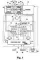
- FIG. 1 a rough figure of a power plant of a vehicle to which a charge control device of the present invention is mounted, is shown.
- a planetary carrier 20 supporting a planetary gear 18 of a planetary gear mechanism 16 is connected to an output shaft 12 of an engine 10.
- a sun gear 22 and a ring gear 24 of the planetary gear mechanism 16 are respectively connected to rotors 30, 32 of a first motor generator 26 and a second motor generator 28.
- the first and second motor generators 26, 28 function as a three-phase alternating current generator or a three-phase alternating current motor.
- a power take-out gear 34 is further connected to the ring gear 24, a power take-out gear 34 is further connected.
- the power take-out gear 34 is connected to a differential gear 40 through a chain 36 and a gear train 38.
- a drive shaft 42 at the tip of which a driving wheel (not shown in the figure) is joined is connected.
- the output power, the rotational speed, and the like thereof are controlled by an engine ECU 46 on the basis of the manipulated variable of an accelerator pedal 44, the environmental conditions such as cooling water temperature or intake manifold pressure, and further, the operational states of the first and second motor generators 26, 28. Furthermore, the first and second motor generators 26, 28 are controlled by a control device 48.
- the control device 48 includes a battery 50 (secondary battery) which supplies the electric power to two motor generators 26, 28 and receives the electric power from them.
- the battery 50 is a nickel hydrogen battery.
- the exchanges of the electric power between the battery 50 and the first and second motor generators 26, 28 are respectively performed through a first inverter 52 and a second inverter 54.
- the control of two inverters 52, 54 is performed by a control CPU 56, based on information of the operational state of the engine 10 from the engine ECU 46, the extent of operation of the accelerator pedal 44, the extent of operation of a brake pedal 58, the shift range determined by a shift lever 60, the state of charge of the battery, and further, the rotational angle ⁇ s of the sun gear, the rotational angle ⁇ c of the planetary carrier, and the rotational angle ⁇ r of the ring gear of the planetary gear mechanism 16, and the like. Furthermore, the rotational angles of three components of said planetary gear mechanism 16 are respectively detected by a planetary carrier resolver 62, a sun gear resolver 64, and a ring gear resolver 66.
- the electric power accumulated in the battery is calculated by a battery ECU 68.
- the control CPU 56 controls transistors Tr1 ⁇ Tr6, Tr11 ⁇ Tr16 of the first and second inverters 52, 54 on the basis of the above mentioned various conditions and the u phase and v phase electric currents Iu1, Iv1, Iu2, Iv2 of the first and second motor generators 26, 28, and further, the electric currents L1, L2 supplied from or supplied to the battery or the inverter on the other side, and the like.
- the rotational speed Nr of the ring gear is determined by the speed of the vehicle and, therefore, if either rotational speed of the rotational speed Nc of the planetary carrier, that is, the speed of the engine, or the rotational speed Ns of the sun gear, that is, the rotational speed of the first motor generator, is found, the other may be determined. Then, the field currents of the first and second motor generators 26, 28 are controlled according to the rotational speeds at that time, and whether these motor generators shall be operated as a generator or operated as a motor, is determined.
- two motor generators 26, 28 consume the electric power as a whole, the electric power is brought out from the battery 50, and if they generate electricity as a whole, the battery 50 is charged.
- power generation may be performed by either or both of the two motor generators 26, 28 by using a part of the torque generated by the engine 10, and the charge to the battery 50 is performed.
- the charge level of the battery 50 is increased, the output power of the engine 10 is a little restrained, and the second motor generator 28 is operated as a motor, and the torque generated by this is controlled so as to be used for the running of the vehicle.
- either or both of the two motor generators 26, 28 are operated as generators, and the generated electric power is accumulated in the battery 50.
- the battery 50 Since it is difficult to predict when the braking of an automobile will be performed, it is desirable that the battery 50 be in a state where the electric power generated by the regenerative braking can sufficiently be received. On the other hand, the battery 50 must be able to ensure a certain charge level for operating the second motor generator 28 as a motor when the output power of the engine 10 alone cannot achieve an acceleration desired by the driver. In order to fulfill this condition, the charge level of the battery 50 is controlled so as to be approximately one half of the battery capacity, that is, the maximum electric power which can be accumulated in the battery. In the present embodiment, the control is performed so that the charge level may be approximately 60%.
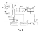
- the battery 50 is a battery assembly having a plurality of cells arranged in series as shown in the figure, and is connected to motor generators 26, 28 through inverters 52, 54.
- the two motor generators 26, 28 are connected to the engine 10 through the transmission mechanism including the planetary gear mechanism.
- a voltage sensor 70 as a voltage detecting means for detecting the terminal voltage of the battery 50
- a current sensor 72 as a current detecting means for detecting the current flowing in the battery 50 are provided.
- temperature sensors 74 as temperature detecting means for detecting the temperature of the battery are provided. Temperature sensors 74 are provided at a plurality of positions because the temperature of the battery 50 differs depending on the positions.
- the outputs of the voltage sensor 70, the current sensor 72, and the temperature sensors 74 are sent to the battery ECU 68.
- the charge level of the battery is calculated on the basis of the obtained voltage and current, and further, the information relating to the temperature is sent out to the control CPU 56.
- the control CPU 56 integrates the data sent from the battery ECU 68 with various types of data of the engine ECU 46 or the like, and determines the operational states of the motor generators 26, 28, and performs the control of the inverters 52, 54 according thereto.
- the electric power accumulated in the battery 50 is consumed by the motor generators 26, 28.
- the regenerative electric power by the motor generators 26, 28 and the electric power from the motor generators 26, 28 as generators driven by the engine are supplied to the battery 50. Consequently, the motor generators 26, 28 and the engine 10 function as charge and discharge means which supply the electric power to the battery 50 and/or consume the electric power of the battery.
- the control CPU 56 which controls the motor generators 26, 28 through the inverters 52, 54, and the engine CPU 46 function as charge and discharge control means which control the charge and discharge means.
- Fig. 3 the characteristic of the terminal voltage relative to the charge level of a nickel hydrogen battery used in the present embodiment, is shown.
- the terminal voltage scarcely changes.
- the charge level is less than 20% including the values near 20%, or in a case where the charge level is more than 80% including the values near 80%, if the charge level changes, this change appears as the terminal voltage, that is, as the external characteristic of the battery.
- the detection of the charge level is performed on the basis of the terminal voltage and the current flowing in the battery.
- This method by which the charge level is calculated by the terminal voltage and the current, is hereafter expressed as the IV judgment, and this area is expressed as the IV judgment area.
- the charge level is estimated by integrating the currents which have flowed in the battery.
- this area is expressed as the estimated area.
- a battery used in a hybrid electric vehicle like the battery 50 of the present embodiment is charged with the regenerative electric power and the electric power generated by using a part of the output of the engine.
- the battery is discharged to drive the motor generators 26, 28. Therefore, charge and discharge are repeated, and the charge level of the battery continuously changes If this change of the charge level is within the estimated area, the battery ECU 68 integrates the amounts of current detected by the current sensor 72 to the initial value in turn, and estimates the charge level at that time. In this integration, the calculation is performed in such a way that the current during the charge is taken as plus and the current during the discharge is taken as minus. Between this estimated value and the actual charge level, a difference arises because of the fact that the charging efficiency changes with the environmental conditions such as the temperature and because of the self discharge during the time when the battery is left as it is for a long time, or the like.
- the calibration is performed in the following manner.
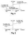
- the battery ECU 68 reads in the value of the current and the value of the voltage from the current sensor 72 and the voltage sensor 70. These values are applied to the IV judgment map shown in Fig. 4 .
- the IV judgment map is prepared by checking in advance the characteristics of the battery 50, and is stored in the storing area in the battery ECU 68. Therefore, the battery ECU 68 functions as an IV judgment map storing means.
- the control CPU 56 is arranged to prohibit the detection of the charge level by the IV judgment and the calibration of said estimated value, when charge and discharge are performed with a heavy current. That is, the calibration of the estimated value of the charge level is performed only in the calibration performing area shown in Fig. 4 . Furthermore, the range of this calibration performing area is changed on the basis of the temperature detected by the temperature sensor 74. In the present embodiment, this range gradually narrows when the temperature becomes below 0°C.
- the calibration of the estimated value of the charge level is performed when the charge level detected by the IV judgment has reached 20% or 80%, but exclusively depends on the operational state of the vehicle that the charge level reaches said values. That is, when the regenerative electric power is generated to some extent and the consumption of the electric power by the motor generator is also proper, there are cases where the charge level does not reach 20% or 80% for a long time. Furthermore, in case such as when the vehicle is not used for a long period, there are times when the charge level stored in the battery ECU 68 from the last operational time may be changed through self discharge of the battery.
- the engine ECU 46 starts the engine 10
- the control CPU 56 operates at least either of the motor generators 26, 28 as a generator, and the battery 50 is charged with this electric power.
- This changing is continued until the IV judgment upper limit line is reached, and at the time when this line is reached, the charge level is calibrated to be 80%.
- the electricity generation of the motor generators 26, 28 is prohibited, and they are made to function as motors, so that the vehicle may run. Consequently, discharge is performed until the IV lower limit judgment line is reached, and, at the time when this line is reached, the charge level is calibrated to be 20%.
- the estimated value of the charge level is fittingly calibrated, and it is arranged so that calibration will not be performed ad infinitum. Furthermore, the drift of the charge level due to self discharge in the state where the vehicle is not used is also corrected at this time. Furthermore, by driving the generator with the engine 10 at the time of start-up, a load can be given to the engine 10, and the operational time for warming-up can be decreased. Furthermore, the charge or discharge is performed, not only when the ignition key is turned on, but also when the above mentioned calibration control is not performed for a specified term, so that the estimated value of the charge level can be calibrated. Furthermore, the value of the current at this time is a value in the above mentioned calibration performing area.
- the charge level of a battery can accurately be detected. Furthermore, by prohibiting the calibration according to the temperature of the battery, a false detection of the charge level because of the temperature of the battery can be prevented.
- the description has been given by taking a battery mounted on a hybrid electric vehicle as an example, but the present invention can be applied to a battery of any applications. Furthermore, it can be applied not only to a nickel hydrogen battery of the present embodiment, but also to a lithium ion battery, a nickel cadmium battery, a lead battery, and the like.
- the battery ECU (68) estimates charge level by integrating the currents of the charge and discharge of the battery
- the engine ECU (46) detects that the ignition key is turned on
- the motor generators (26, 28) are driven by the engine (10), and the generated electric power is accumulated in the battery (50).
- the calculation of the charge level is performed from the current and voltage at that time.
- this charge level has reached 80%, the calibration of said estimated charge level is performed by this value.
- this calibration it is also possible for this calibration to be prohibited when a heavy current is flowing and the error may become large in the calculation of the charge level.
Landscapes
- Physics & Mathematics (AREA)
- General Physics & Mathematics (AREA)
- Electric Propulsion And Braking For Vehicles (AREA)
- Tests Of Electric Status Of Batteries (AREA)
- Secondary Cells (AREA)
- Charge And Discharge Circuits For Batteries Or The Like (AREA)
Claims (5)
- Batterieladungsniveauerfassungsvorrichtung, die angepasst ist, das Ladungsniveau einer Akkumulatorenbatterie (50) zu erfassen, wobei es ein erstes Gebiet des Ladungsniveaus gibt, in dem das Ladungsniveau nicht mehr als ungefähr 20% oder nicht weniger als ungefähr 80% ist, und ein zweites Gebiet des Ladungsniveaus gibt, in dem das Ladungsniveau zwischen ungefähr 20% und ungefähr 80% ist, mit:einer Ladungsniveauschätzeinrichtung (68), die angepasst ist, das Ladungsniveau auf der Grundlage der Ströme des Ladens und Entladens der Akkumulatorenbatterie zu schätzen, wenn das Ladungsniveau in dem zweiten Gebiet des Ladungsniveaus ist;einer Ladungsniveauberechnungseinrichtung (68), die angepasst ist, das Ladungsniveau auf der Grundlage einer Klemmenspannung und der Ströme das Ladens und Entladens der Akkumulatorenbatterie zu berechnen, wenn das Ladungsniveau in dem ersten Gebiet des Ladungsniveaus;einer Ladungsniveaukalibriereinrichtung (68), die angepasst ist, das geschätzte Ladungsniveau durch das berechnete Ladungsniveau zu kalibrieren, wenn das Ladungsniveau in dem ersten Gebiet des Ladungsniveaus ist;einer Lade- und Entladevorrichtung (10, 26, 28), die angepasst ist, die elektrische Leistung an die Akkumulatorenbatterie (50) anzulegen oder die elektrische Leistung der Akkumulatorenbatterie (50) zu verbrauchen; undeiner Lade- und Entladesteuerungseinrichtung (46, 68), die angepasst ist, den Bedarf nach einer Kalibrierung des Ladungsniveaus zu beurteilen, wenn das durch die Ladungsniveauschätzeinrichtung geschätzte Ladungsniveau in das erste Gebiet des Ladungsniveaus eingetreten ist, und angepasst ist, das Durchführen der Kalibrierung zu steuern, wenn das Ladungsniveau der Akkumulatorenbatterie in dem ersten Gebiet des Ladungsniveaus ist.
- Batterieladungsniveauerfassungseinrichtung gemäß Anspruch 1, wobei die Ladungsniveauberechnungseinrichtung (68) angepasst ist, die Berechnung des Ladungsniveaus nur in einem Fall durchzuführen, in dem der Strom nicht größer als ein spezifizierter Wert ist.
- Batterieladungsniveauerfassungseinrichtung nach Anspruch 1 oder Anspruch 2, wobei die Lade- und Entladesteuerungseinrichtung (46, 68) eine Hochlauferfassungseinrichtung enthält, die angepasst ist, den Hochlauf der Lade- und Entladevorrichtung (10, 26, 28) zu erfassen, so dass das Ladungsniveau der Akkumulatorenbatterie das erste Gebiet des Ladungsniveaus erreicht, wenn der Hochlauf der Lade- und Entladeeinrichtung erfasst wird.
- Batterieladeniveauerfassungseinrichtung nach Anspruch 3, mit einer Verhinderungseinrichtung, die angepasst ist, die Steuerung der Lade- und Entladesteuerungseinrichtung zu verhindern in einem Fall, in dem die Lade- und Entladeeinrichtung hochgefahren wird, und die Zeit, die abgelaufen ist, nachdem die letzte Steuerung durch das Lade- und Entladesteuerungseinrichtung (46, 68) durchgeführt wurde, so dass das Ladungsniveau der Akkumulatorenbatterie das erste Gebiet des Ladungsniveau erreicht hatte, abgelaufen ist, noch nicht eine spezifizierte Zeit erreicht hat.
- Batterieladungsniveauerfassungseinrichtung nach einem der Ansprüche 1 bis 4, wobei die Lade- und Entladesteuerungseinrichtung (46, 68) ferner konfiguriert ist, die Lade- und Entladevorrichtung (10, 26, 28) zu steuern.
Priority Applications (1)
| Application Number | Priority Date | Filing Date | Title |
|---|---|---|---|
| EP08152623A EP1933160B1 (de) | 1997-10-13 | 1998-10-12 | Vorrichtung zur Erkennung des Ladezustands einer Batterie |
Applications Claiming Priority (3)
| Application Number | Priority Date | Filing Date | Title |
|---|---|---|---|
| JP278801/97 | 1997-10-13 | ||
| JP27880197 | 1997-10-13 | ||
| JP27880197A JP3225901B2 (ja) | 1997-10-13 | 1997-10-13 | 電池蓄電量検出装置 |
Related Child Applications (2)
| Application Number | Title | Priority Date | Filing Date |
|---|---|---|---|
| EP08152623A Division EP1933160B1 (de) | 1997-10-13 | 1998-10-12 | Vorrichtung zur Erkennung des Ladezustands einer Batterie |
| EP08152623.8 Division-Into | 2008-03-12 |
Publications (3)
| Publication Number | Publication Date |
|---|---|
| EP0908737A2 EP0908737A2 (de) | 1999-04-14 |
| EP0908737A3 EP0908737A3 (de) | 2000-07-12 |
| EP0908737B1 true EP0908737B1 (de) | 2010-08-18 |
Family
ID=17602372
Family Applications (2)
| Application Number | Title | Priority Date | Filing Date |
|---|---|---|---|
| EP98119246A Expired - Lifetime EP0908737B1 (de) | 1997-10-13 | 1998-10-12 | Einrichtung zur Batterieladungsniveauermittlung |
| EP08152623A Expired - Lifetime EP1933160B1 (de) | 1997-10-13 | 1998-10-12 | Vorrichtung zur Erkennung des Ladezustands einer Batterie |
Family Applications After (1)
| Application Number | Title | Priority Date | Filing Date |
|---|---|---|---|
| EP08152623A Expired - Lifetime EP1933160B1 (de) | 1997-10-13 | 1998-10-12 | Vorrichtung zur Erkennung des Ladezustands einer Batterie |
Country Status (5)
| Country | Link |
|---|---|
| US (1) | US6127805A (de) |
| EP (2) | EP0908737B1 (de) |
| JP (1) | JP3225901B2 (de) |
| CA (1) | CA2249949C (de) |
| DE (2) | DE69841816D1 (de) |
Families Citing this family (21)
| Publication number | Priority date | Publication date | Assignee | Title |
|---|---|---|---|---|
| JP3225901B2 (ja) | 1997-10-13 | 2001-11-05 | トヨタ自動車株式会社 | 電池蓄電量検出装置 |
| US6232744B1 (en) | 1999-02-24 | 2001-05-15 | Denso Corporation | Method of controlling battery condition of self-generation electric vehicle |
| JP4753146B2 (ja) * | 2001-04-25 | 2011-08-24 | 株式会社デンソー | バッテリ残量表示装置 |
| JP2003180038A (ja) * | 2001-12-11 | 2003-06-27 | Rohm Co Ltd | 充電制御装置 |
| US20040020695A1 (en) * | 2002-08-05 | 2004-02-05 | Ford Motor Company | Apparatus and a method for determining hybrid-electric vehicle performance |
| US8427109B2 (en) * | 2004-04-06 | 2013-04-23 | Chevron Technology Ventures Llc | Battery state of charge reset |
| JP4544273B2 (ja) | 2007-06-20 | 2010-09-15 | トヨタ自動車株式会社 | 車両用電源装置および車両用電源装置における蓄電装置の充電状態推定方法 |
| GB0812198D0 (en) * | 2008-07-03 | 2008-08-13 | Xipower Ltd | Improvements in and relating to battery management |
| JP2011083082A (ja) * | 2009-10-05 | 2011-04-21 | Panasonic Electric Works Co Ltd | 蓄電システム |
| IT1397174B1 (it) | 2009-10-27 | 2013-01-04 | F I A M M Spa | Metodo per la rilevazione continua dell'efficienza di una batteria specie di una batteria installata in autoveicoli e dispositivo utilizzante tale metodo |
| JP5287844B2 (ja) * | 2010-12-27 | 2013-09-11 | 株式会社デンソー | 二次電池の残存容量演算装置 |
| DE102011102423A1 (de) | 2011-05-24 | 2012-11-29 | Audi Ag | Verfahren zum Betrieb eines Kraftfahrzeugs |
| JP5846170B2 (ja) * | 2013-08-07 | 2016-01-20 | Tdk株式会社 | 蓄電システムおよびそれを用いた電動車両 |
| CN104734214B (zh) * | 2013-12-18 | 2018-08-14 | 比亚迪股份有限公司 | 便携式设备及其的充放电控制方法 |
| EP3214754B1 (de) * | 2014-10-30 | 2020-10-14 | Hitachi Automotive Systems, Ltd. | Motorsteuerungsvorrichtung |
| JP7271343B2 (ja) * | 2019-07-03 | 2023-05-11 | 株式会社デンソーテン | 推定装置、電池システムおよび推定方法 |
| JP7436317B2 (ja) * | 2020-07-29 | 2024-02-21 | 日立建機株式会社 | 電動作業機械 |
| US20240149711A1 (en) | 2022-11-04 | 2024-05-09 | Oshkosh Corporation | Electrified fire fighting vehicle |
| US20240149808A1 (en) | 2022-11-04 | 2024-05-09 | Oshkosh Corporation | High voltage cable routing for electrified vehicle |
| US20240149659A1 (en) | 2022-11-04 | 2024-05-09 | Oshkosh Corporation | Electrified fire fighting vehicle |
| CN115817231B (zh) * | 2022-12-15 | 2024-04-30 | 小米汽车科技有限公司 | 电动汽车及其充电装置 |
Family Cites Families (10)
| Publication number | Priority date | Publication date | Assignee | Title |
|---|---|---|---|---|
| JPH02163680A (ja) * | 1988-12-19 | 1990-06-22 | Meidensha Corp | 蓄電池の残容量表示方式 |
| FR2670953B1 (fr) * | 1990-12-21 | 1993-03-05 | Travaux Electr Ste Gle | Procede et dispositif pour charger un accumulateur. |
| US5325041A (en) * | 1991-08-09 | 1994-06-28 | Briggs James B | Automatic rechargeable battery monitoring system |
| US5321627A (en) * | 1992-03-11 | 1994-06-14 | Globe-Union, Inc. | Battery monitor and method for providing operating parameters |
| DE4337020C1 (de) * | 1993-10-29 | 1994-12-08 | Daimler Benz Ag | Verfahren zur Überwachung der Batterie eines Hybridfahrzeugs |
| US5596260A (en) * | 1994-05-13 | 1997-01-21 | Apple Computer, Inc. | Apparatus and method for determining a charge of a battery |
| JP3178315B2 (ja) * | 1994-11-21 | 2001-06-18 | セイコーエプソン株式会社 | バッテリ残存容量計及び残存容量算出方法 |
| JP3162964B2 (ja) * | 1995-09-01 | 2001-05-08 | 矢崎総業株式会社 | 電池残存容量測定装置 |
| JPH0972984A (ja) | 1995-09-04 | 1997-03-18 | Ishikawajima Harima Heavy Ind Co Ltd | 沸騰水型原子炉圧力容器の冷却水誘導装置 |
| JP3225901B2 (ja) | 1997-10-13 | 2001-11-05 | トヨタ自動車株式会社 | 電池蓄電量検出装置 |
-
1997
- 1997-10-13 JP JP27880197A patent/JP3225901B2/ja not_active Expired - Lifetime
-
1998
- 1998-10-08 US US09/168,073 patent/US6127805A/en not_active Expired - Lifetime
- 1998-10-09 CA CA002249949A patent/CA2249949C/en not_active Expired - Lifetime
- 1998-10-12 EP EP98119246A patent/EP0908737B1/de not_active Expired - Lifetime
- 1998-10-12 DE DE69841816T patent/DE69841816D1/de not_active Expired - Lifetime
- 1998-10-12 DE DE69841840T patent/DE69841840D1/de not_active Expired - Lifetime
- 1998-10-12 EP EP08152623A patent/EP1933160B1/de not_active Expired - Lifetime
Also Published As
| Publication number | Publication date |
|---|---|
| JP3225901B2 (ja) | 2001-11-05 |
| EP1933160B1 (de) | 2010-08-04 |
| DE69841816D1 (de) | 2010-09-16 |
| EP1933160A2 (de) | 2008-06-18 |
| DE69841840D1 (de) | 2010-09-30 |
| CA2249949C (en) | 2001-08-07 |
| JPH11121048A (ja) | 1999-04-30 |
| EP1933160A3 (de) | 2008-07-23 |
| US6127805A (en) | 2000-10-03 |
| EP0908737A3 (de) | 2000-07-12 |
| EP0908737A2 (de) | 1999-04-14 |
| CA2249949A1 (en) | 1999-04-13 |
Similar Documents
| Publication | Publication Date | Title |
|---|---|---|
| EP0908737B1 (de) | Einrichtung zur Batterieladungsniveauermittlung | |
| US6104166A (en) | Method and device for detecting a state of charge of a battery assembly, and battery assembly charge and discharge control device | |
| EP0909675B1 (de) | Lade- und Entladungsregelvorrichtung für eine zweite Batterie | |
| US8288998B2 (en) | Method and apparatus for charge discharge power control | |
| EP0985570B1 (de) | Vorrichtung und Verfahren zur Steuerung des Lade-/Entladezustandes der Batterie eines Hybridfahrzeuges | |
| US7982435B2 (en) | Battery charging and discharging control apparatus | |
| US7019472B2 (en) | Vehicle controller that stably supplies power to a battery and method thereof | |
| US6837215B2 (en) | Automobile and controlling method for automobile | |
| US6377880B1 (en) | Cooling fan failure detection apparatus for hybrid vehicle | |
| EP2474833B1 (de) | Vorrichtung und verfahren zur ladestatuserkennung bei einer montierten batterie | |
| US8140207B2 (en) | Vehicle and control method thereof | |
| US6965824B2 (en) | Power output apparatus and automobile with power output apparatus mounted thereon | |
| KR100834520B1 (ko) | 전기자동차 및 그 제어방법 | |
| JP3783391B2 (ja) | 二次電池装置 | |
| EP0915552B1 (de) | Akkumulatorsteuergerät | |
| JP3959815B2 (ja) | 電池蓄電量検出装置 | |
| JP2000166105A (ja) | バッテリ充電状態制御装置 | |
| KR100435683B1 (ko) | 하이브리드 전기자동차의 충전 제어방법 |
Legal Events
| Date | Code | Title | Description |
|---|---|---|---|
| PUAI | Public reference made under article 153(3) epc to a published international application that has entered the european phase |
Free format text: ORIGINAL CODE: 0009012 |
|
| 17P | Request for examination filed |
Effective date: 19981013 |
|
| AK | Designated contracting states |
Kind code of ref document: A2 Designated state(s): DE FR GB IT |
|
| AX | Request for extension of the european patent |
Free format text: AL;LT;LV;MK;RO;SI |
|
| PUAL | Search report despatched |
Free format text: ORIGINAL CODE: 0009013 |
|
| AK | Designated contracting states |
Kind code of ref document: A3 Designated state(s): AT BE CH CY DE DK ES FI FR GB GR IE IT LI LU MC NL PT SE |
|
| AX | Request for extension of the european patent |
Free format text: AL;LT;LV;MK;RO;SI |
|
| AKX | Designation fees paid |
Free format text: DE FR GB IT |
|
| 17Q | First examination report despatched |
Effective date: 20071102 |
|
| GRAP | Despatch of communication of intention to grant a patent |
Free format text: ORIGINAL CODE: EPIDOSNIGR1 |
|
| GRAS | Grant fee paid |
Free format text: ORIGINAL CODE: EPIDOSNIGR3 |
|
| GRAA | (expected) grant |
Free format text: ORIGINAL CODE: 0009210 |
|
| AK | Designated contracting states |
Kind code of ref document: B1 Designated state(s): DE FR GB IT |
|
| REG | Reference to a national code |
Ref country code: GB Ref legal event code: FG4D |
|
| REF | Corresponds to: |
Ref document number: 69841840 Country of ref document: DE Date of ref document: 20100930 Kind code of ref document: P |
|
| PLBE | No opposition filed within time limit |
Free format text: ORIGINAL CODE: 0009261 |
|
| STAA | Information on the status of an ep patent application or granted ep patent |
Free format text: STATUS: NO OPPOSITION FILED WITHIN TIME LIMIT |
|
| 26N | No opposition filed |
Effective date: 20110519 |
|
| REG | Reference to a national code |
Ref country code: DE Ref legal event code: R097 Ref document number: 69841840 Country of ref document: DE Effective date: 20110519 |
|
| REG | Reference to a national code |
Ref country code: GB Ref legal event code: 746 Effective date: 20130717 |
|
| REG | Reference to a national code |
Ref country code: DE Ref legal event code: R084 Ref document number: 69841840 Country of ref document: DE Effective date: 20130717 |
|
| REG | Reference to a national code |
Ref country code: FR Ref legal event code: PLFP Year of fee payment: 19 |
|
| REG | Reference to a national code |
Ref country code: FR Ref legal event code: PLFP Year of fee payment: 20 |
|
| PGFP | Annual fee paid to national office [announced via postgrant information from national office to epo] |
Ref country code: FR Payment date: 20170918 Year of fee payment: 20 |
|
| PGFP | Annual fee paid to national office [announced via postgrant information from national office to epo] |
Ref country code: DE Payment date: 20171004 Year of fee payment: 20 |
|
| PGFP | Annual fee paid to national office [announced via postgrant information from national office to epo] |
Ref country code: IT Payment date: 20171024 Year of fee payment: 20 Ref country code: GB Payment date: 20171011 Year of fee payment: 20 |
|
| REG | Reference to a national code |
Ref country code: DE Ref legal event code: R071 Ref document number: 69841840 Country of ref document: DE |
|
| REG | Reference to a national code |
Ref country code: GB Ref legal event code: PE20 Expiry date: 20181011 |
|
| PG25 | Lapsed in a contracting state [announced via postgrant information from national office to epo] |
Ref country code: GB Free format text: LAPSE BECAUSE OF EXPIRATION OF PROTECTION Effective date: 20181011 |