EP0908752A1 - Dispositif d'observation à travers la paroi d'une enceinte de protection à l'aide d'un épiscope - Google Patents
Dispositif d'observation à travers la paroi d'une enceinte de protection à l'aide d'un épiscope Download PDFInfo
- Publication number
- EP0908752A1 EP0908752A1 EP98402361A EP98402361A EP0908752A1 EP 0908752 A1 EP0908752 A1 EP 0908752A1 EP 98402361 A EP98402361 A EP 98402361A EP 98402361 A EP98402361 A EP 98402361A EP 0908752 A1 EP0908752 A1 EP 0908752A1
- Authority
- EP
- European Patent Office
- Prior art keywords
- mirror
- observation device
- episcope
- observation
- window
- Prior art date
- Legal status (The legal status is an assumption and is not a legal conclusion. Google has not performed a legal analysis and makes no representation as to the accuracy of the status listed.)
- Granted
Links
- 230000001681 protective effect Effects 0.000 title claims description 3
- 230000001154 acute effect Effects 0.000 claims description 3
- 230000005540 biological transmission Effects 0.000 claims description 2
- 238000002513 implantation Methods 0.000 description 2
- 238000009434 installation Methods 0.000 description 2
- 206010001488 Aggression Diseases 0.000 description 1
- 230000016571 aggressive behavior Effects 0.000 description 1
- 239000011324 bead Substances 0.000 description 1
- 230000000903 blocking effect Effects 0.000 description 1
- 238000012423 maintenance Methods 0.000 description 1
- 230000003287 optical effect Effects 0.000 description 1
- 239000000126 substance Substances 0.000 description 1
- 238000003466 welding Methods 0.000 description 1
Images


Classifications
-
- F—MECHANICAL ENGINEERING; LIGHTING; HEATING; WEAPONS; BLASTING
- F41—WEAPONS
- F41G—WEAPON SIGHTS; AIMING
- F41G1/00—Sighting devices
- F41G1/40—Periscopic sights specially adapted for smallarms or ordnance; Supports or mountings therefor
-
- F—MECHANICAL ENGINEERING; LIGHTING; HEATING; WEAPONS; BLASTING
- F41—WEAPONS
- F41H—ARMOUR; ARMOURED TURRETS; ARMOURED OR ARMED VEHICLES; MEANS OF ATTACK OR DEFENCE, e.g. CAMOUFLAGE, IN GENERAL
- F41H5/00—Armour; Armour plates
- F41H5/26—Peepholes; Windows; Loopholes
- F41H5/266—Periscopes for fighting or armoured vehicles
-
- G—PHYSICS
- G02—OPTICS
- G02B—OPTICAL ELEMENTS, SYSTEMS OR APPARATUS
- G02B23/00—Telescopes, e.g. binoculars; Periscopes; Instruments for viewing the inside of hollow bodies; Viewfinders; Optical aiming or sighting devices
- G02B23/02—Telescopes, e.g. binoculars; Periscopes; Instruments for viewing the inside of hollow bodies; Viewfinders; Optical aiming or sighting devices involving prisms or mirrors
- G02B23/08—Periscopes
Definitions
- the invention relates to an observation device with through the wall of a protective enclosure using a episcope, that is to say an optical instrument allowing to observe through a wall behind which the observer is protected.
- the object of the present invention is to provide a observation device implanted in the wall of a vehicle and protruding only slightly inside of this vehicle.
- the invention proposes a observation device through the wall of an enclosure protection, such as a military vehicle, using a episcope fixed at the level of said wall provided with a window external light beam entry and window internal outlet, characterized in that it comprises a retractable mirror cooperating with a transparent block for ensure the transmission of light rays in a identical or opposite direction of observation.
- the transparent block has one or two sides of reflection.
- the mirror is retractable by rotation.
- the observation device includes a system articulated connecting the mirror to the episcope allowing the mirror to occupy a retracted position in which this is applied against the exit window and a deployed position in which the mirror allows observation.
- the articulated system consists of a base fitted a groove, a hinged support at one end of the base and an arm connected at one end to the support and to the other has a sliding axis in the groove.
- the exit window of the episcope is tilted by acute angle to a plane passing through the window entry.
- the mirror can be folded against the exit window or the opposite of it.
- the articulated system consists of a support whose the end is articulated with respect to the episcope and has a semi-cylindrical surface cooperating with a means for holding the mirror in an angular position determined.
- the mirror is retractable by translation.
- the mirror is of the flat or concave type.
- a very first advantage of the invention lies in the fact that the space requirement is reduced for the observer, which facilitates access to its observation post.
- Another advantage of the invention lies in variable adjustment of the mirror position depending the size of the observer.
- FIG 1 there is shown schematically a vehicle 1, for example a vehicle of the military type, with which the combatants are brought to move.
- the internal enclosure conventionally constitutes protection against ballistic, nuclear, biological aggressions and chemicals.
- an episcope 3 On the upper wall 2 of the enclosure, we fixes an episcope 3 whose role is to allow a fighter 12 to observe his outside environment, following field E in a direction opposite to the gaze direction. This direction could be good heard that of the look.
- the lower part of an episcope known has been eliminated and replaced with a face retractable reflective.
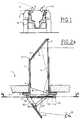
- the episcope 3 is integrated into an opening 4 made in the wall 2 and comprises conventionally a cover 5 and a transparent mass 6 here equipped with two reflecting faces 6a and 6b.
- the episcope is fixed via the rim 7 of the cover 5, a seal 8 being interposed between this rim and the wall 2.
- the episcope 3 therefore comprises a entry window 9 arranged substantially vertically at projecting outside and an exit window 10.
- the window 10 is tilted at an acute angle relative to a plane passing through the entrance window 9 to cooperate with a mirror 11 in order to cover the field of vision of the episcope on the one hand and to compensate for the variations of tilt of the mirror related to the size of the observer.
- the light rays coming from outside are therefore think twice before hitting the mirror 11.
- the mirror 11 is made retractable by rotation at using an articulated system comprising a base 13 integral with the rim 7 or the wall 2, for example by screwing or welding.
- the base 13 is provided with a slot 14 longitudinal and an axis 15, held in a position fixed, around which the support 16 of the mirror pivots.
- a connecting rod 17 is fixedly connected to the support 16 by a axis 18 distant from axis 15 and to an axis 19 sliding in the slot 14.
- the articulated system is therefore delimited by the base 13, the support 14 and the connecting rod 17 and gives the mirror 11 any angular position relative to the exit window 10.
- FIG. 2B there is shown an episcope 6 almost identical to that of FIG. 2A with the exception of the upper part projecting from the enclosure 2.
- the episcope 6 has only one reflective face 6c for transmitting rays bright in the direction of the viewer's gaze. The light ray undergoes only one reflection before reaching the mirror 11.
- the slot 14 is made at the level of the base 13. It could be arranged without difficulty on the support 16 of the mirror, the connecting rod 17 being then fixed on the base. There is shown a slot 14 occupying practically the width of the base to allow the retraction of the mirror 11 either towards the base 13 as shown in Figure 3, opposite to it in the extension of the base as shown in Figure 4.
- FIG. 3 there is shown the mirror 11 in its retracted position, that is, it was brought back against the outlet window 10 by rotation, means being provided to maintain this mirror 7 in this position.
- the episcope 3 thus modified no longer constitutes embarrassment for the fighter when he wants to access his post or get out. Congestion, especially in height, is therefore reduced to a minimum.
- the combatant can observe the environment in front (fig. 2B) or behind him (fig.2A).
- the mirror 11 is folded against the base 13 towards the outlet window 10, the connecting rod 17 being applied against the base and the axis 19 being placed at the level of the free end of the slot 14 not visible on the drawing.
- the mirror 11 is folded down in the opposite direction to that of figure 2, the window of outlet 10 being completely clear.
- the axis 19 fixed to the connecting rod 17 is brought back in the vicinity of the axis 15 fixed in the vicinity of the other end of the slot 14.
- Figure 5 illustrates another variant of realization of the retraction of the mirror 11 by rotation.
- This mirror is fixed to a support 20 extended by one end 21 semi-cylindrical fixed to the edge 7 of the cover 5 of the episcope 3.
- the end 21 is provided on its periphery a toothing 22 intended to cooperate with a ball 23 subjected to the action of a spring 24 engaged in a housing blind 25 practiced in a bead 26 integrated into the rim 7.
- the support 20 is rotatably mounted by relative to an axis 27 integral with the rim 7 or the wall 2.
- the ball 23 ensures the maintenance of the mirror 11 in the angular position desired by the user.
- the tooth upper determines the retracting position of the mirror and the lower tooth fixes the maximum spacing of the mirror 11 relative to the exit window 10 of the episcope 3.
- Figures 6 and 7 illustrate the retraction of the mirror 11 by translation.
- the mirror 11 is integral a support 28 comprising an inclined bottom 29, on which the mirror is fixed, and two side walls 30, one of which only is shown in the figures.
- window 9 could be oriented as shown in Figure 2B.
- the walls 30 carry fingers 31 to slide relative to two guides 32 provided grooves 33 (only one guide is visible in the figures).
- the walls 30 and the guides 32 are arranged two to two on each side of the episcope, for example in the cover 5 thereof.
- Figure 6 shows the position lower of mirror 11 and figure 7 the position retraction to the exit window 10.
- Figures 8 and 9 illustrate sections AA according to the FIG. 2A with a device for indexing the mirror 11.
- Figure 8 shows a first embodiment according to which the connecting rod 17 is rigidly fixed on one side to the support 16 by axis 18 and connected at the other end to the base 13 by the axis 19 extended externally by a button 41.
- the axis 19 slides in a body 42 connected to the base 13, a spring 43 holding said axis in abutment constant in groove 14 to ensure indexing.
- FIG. 9 illustrates an indexing system 45 according to which constant support is obtained by a ball 46 submitted to the action of a spring 47, the assembly being integrated in a cover 48.
Landscapes
- Physics & Mathematics (AREA)
- Engineering & Computer Science (AREA)
- General Engineering & Computer Science (AREA)
- Optics & Photonics (AREA)
- Astronomy & Astrophysics (AREA)
- General Physics & Mathematics (AREA)
- Rear-View Mirror Devices That Are Mounted On The Exterior Of The Vehicle (AREA)
Abstract
Description
- la figure 1 représente une vue générale de l'implantation du dispositif selon l'invention dans un véhicule,
- les figures 2A et 2B représente des vues en coupe schématique montrant l'implantation du dispositif d'observation en position d'utilisation,
- les figures 3 et 4 représentent des vues schématiques montrant le miroir en position escamotée,
- la figure 5 montre une variante de la structure des moyens d'articulation,
- les figures 6 et 7 montrent des moyens d'escamotage en translation,
- et les figures 8 et 9 représentent des coupes AA de la figure 2 montrant notamment les moyens de blocage de la position angulaire du miroir.
Claims (10)
- Dispositif d'observation à travers la paroi d'une enceinte de protection, telle un véhicule militaire, à l'aide d'un épiscope (3) fixé au niveau de ladite paroi (2) muni d'une fenêtre externe d'entrée (9) de rayons lumineux et d'une fenêtre interne de sortie (10), caractérisé en ce qu'il comprend un miroir escamotable (11) coopérant avec un bloc tranparent (6) pour assurer la transmission des rayons lumineux dans une direction identique ou opposée à la direction d'observation.
- Dispositif d'observation selon la revendication 1, caractérisé en ce que le bloc transparent (6) comporte une (9c) ou deux faces (9a, 9b) de réflexion.
- Dispositif d'observation selon la revendication 2, caractérisé en ce que le miroir (11) est escamotable par rotation.
- Dispositif d'observation selon la revendication 3, caractérisé en ce qu'il comprend un système articulé (13, 16, 17) reliant le miroir (11) à l'épiscope (3) permettant au miroir (11) d'occuper une position escamotée dans laquelle celui-ci est appliqué contre la fenêtre de sortie (10) et une position déployée dans laquelle le miroir (11) permet l'observation.
- Dispositif d'observation selon la revendication 4, caractérisé en ce que le système articulé est constitué d'une embase (13) munie d'une rainure (14), d'un support (16) articulé à une extrémité de l'embase et d'un bras (17) relié à une extrémité au support et à l'autre à un axe (19) coulissant dans la rainure.
- Dispositif d'observation selon la revendication 5, caractérisé en ce que la fenêtre de sortie (10) de l'épiscope est inclinée d'un angle aigu par rapport à un plan passant par le fenêtre d'entrée (9).
- Dispositif d'observation selon la revendication 6, caractérisé en ce que le miroir (11) est rabattable contre la fenêtre de sortie ou à l'opposé de celle-ci.
- Dispositif d'observation selon la revendication 3, caractérisé en ce que le système articulé est constitué d'un support (20) dont l'extrémité est articulée par rapport à l'épiscope et présente une surface semi-cylindrique coopérant avec un moyen de maintien du miroir dans une position angulaire déterminée.
- Dispositif d'observation selon la revendication 1, caractérisé en ce que le miroir (7) est escamotable par translation.
- Dispositif d'observation selon l'une quelconque des revendications précédentes, caractérisé en ce que le miroir (7) est du type plan ou concave.
Applications Claiming Priority (2)
| Application Number | Priority Date | Filing Date | Title |
|---|---|---|---|
| FR9712468 | 1997-10-07 | ||
| FR9712468A FR2769378B1 (fr) | 1997-10-07 | 1997-10-07 | Dispositif d'observation a travers la paroi d'une enceinte de protection a l'aide d'un episcope |
Publications (2)
| Publication Number | Publication Date |
|---|---|
| EP0908752A1 true EP0908752A1 (fr) | 1999-04-14 |
| EP0908752B1 EP0908752B1 (fr) | 2004-07-07 |
Family
ID=9511900
Family Applications (1)
| Application Number | Title | Priority Date | Filing Date |
|---|---|---|---|
| EP19980402361 Expired - Lifetime EP0908752B1 (fr) | 1997-10-07 | 1998-09-25 | Dispositif d'observation à travers la paroi d'une enceinte de protection à l'aide d'un épiscope |
Country Status (3)
| Country | Link |
|---|---|
| EP (1) | EP0908752B1 (fr) |
| DE (1) | DE69824931T2 (fr) |
| FR (1) | FR2769378B1 (fr) |
Cited By (2)
| Publication number | Priority date | Publication date | Assignee | Title |
|---|---|---|---|---|
| GB2519767A (en) * | 2013-10-29 | 2015-05-06 | Kent Periscopes Ltd | Periscope |
| FR3015697A1 (fr) * | 2013-12-19 | 2015-06-26 | France Etat | Episcope de crevel |
Families Citing this family (3)
| Publication number | Priority date | Publication date | Assignee | Title |
|---|---|---|---|---|
| FR2882445B1 (fr) * | 2005-02-24 | 2007-06-01 | Giat Ind Sa | Dispositif d'observation a episcope escamotable |
| DE102008021486B4 (de) * | 2008-04-29 | 2010-06-24 | Krauss-Maffei Wegmann Gmbh & Co. Kg | Klappwinkelspiegel für Kampffahrzeuge |
| DE102015122411A1 (de) | 2015-12-21 | 2017-06-22 | Krauss-Maffei Wegmann Gmbh & Co. Kg | Klappwinkelspiegel und Ausblickvorrichtung |
Citations (12)
| Publication number | Priority date | Publication date | Assignee | Title |
|---|---|---|---|---|
| FR407463A (fr) * | 1909-09-30 | 1910-03-01 | Marie Alexandre Leon Lefebure | Appareil reproduisant sous les yeux d'un observateur l'image des objets placés derrière lui |
| US1466567A (en) * | 1920-09-03 | 1923-08-28 | Raymond W Smith | Reflector for autos |
| US2130006A (en) * | 1935-02-04 | 1938-09-13 | Gundlach Rudolf | Periscope for armored vehicles |
| US2570357A (en) * | 1950-03-08 | 1951-10-09 | Tolly C Martin | Periscope for motor vehicles |
| FR1170518A (fr) * | 1957-04-01 | 1959-01-15 | Dispositif de fixation d'un épiscope de véhicule blindé | |
| US3165573A (en) * | 1958-09-29 | 1965-01-12 | Charles W Moultrie | Vision device for vehicles |
| US3229576A (en) * | 1962-11-21 | 1966-01-18 | Donald W Rees | Hyperbolic ellipsoidal real time display panoramic viewing installation for vehicles |
| US3857632A (en) * | 1971-10-11 | 1974-12-31 | Ichikoh Industries Ltd | Rear vision mirror apparatus having a filter for automobile |
| GB2089519A (en) * | 1980-12-17 | 1982-06-23 | Philips Electronic Associated | Stowable sighting instrument |
| FR2496905A1 (fr) * | 1980-12-24 | 1982-06-25 | France Etat | Episcope a reflexions multimodes |
| EP0550869A1 (fr) * | 1992-01-08 | 1993-07-14 | Wegmann & Co. GmbH | Mirroir d'angle sur la trappe d'un véhicule de combat |
| EP0608907A1 (fr) * | 1990-05-12 | 1994-08-03 | Wegmann & Co. GmbH | Miroir d'angle pour chars de combat |
-
1997
- 1997-10-07 FR FR9712468A patent/FR2769378B1/fr not_active Expired - Fee Related
-
1998
- 1998-09-25 DE DE69824931T patent/DE69824931T2/de not_active Expired - Lifetime
- 1998-09-25 EP EP19980402361 patent/EP0908752B1/fr not_active Expired - Lifetime
Patent Citations (12)
| Publication number | Priority date | Publication date | Assignee | Title |
|---|---|---|---|---|
| FR407463A (fr) * | 1909-09-30 | 1910-03-01 | Marie Alexandre Leon Lefebure | Appareil reproduisant sous les yeux d'un observateur l'image des objets placés derrière lui |
| US1466567A (en) * | 1920-09-03 | 1923-08-28 | Raymond W Smith | Reflector for autos |
| US2130006A (en) * | 1935-02-04 | 1938-09-13 | Gundlach Rudolf | Periscope for armored vehicles |
| US2570357A (en) * | 1950-03-08 | 1951-10-09 | Tolly C Martin | Periscope for motor vehicles |
| FR1170518A (fr) * | 1957-04-01 | 1959-01-15 | Dispositif de fixation d'un épiscope de véhicule blindé | |
| US3165573A (en) * | 1958-09-29 | 1965-01-12 | Charles W Moultrie | Vision device for vehicles |
| US3229576A (en) * | 1962-11-21 | 1966-01-18 | Donald W Rees | Hyperbolic ellipsoidal real time display panoramic viewing installation for vehicles |
| US3857632A (en) * | 1971-10-11 | 1974-12-31 | Ichikoh Industries Ltd | Rear vision mirror apparatus having a filter for automobile |
| GB2089519A (en) * | 1980-12-17 | 1982-06-23 | Philips Electronic Associated | Stowable sighting instrument |
| FR2496905A1 (fr) * | 1980-12-24 | 1982-06-25 | France Etat | Episcope a reflexions multimodes |
| EP0608907A1 (fr) * | 1990-05-12 | 1994-08-03 | Wegmann & Co. GmbH | Miroir d'angle pour chars de combat |
| EP0550869A1 (fr) * | 1992-01-08 | 1993-07-14 | Wegmann & Co. GmbH | Mirroir d'angle sur la trappe d'un véhicule de combat |
Cited By (5)
| Publication number | Priority date | Publication date | Assignee | Title |
|---|---|---|---|---|
| GB2519767A (en) * | 2013-10-29 | 2015-05-06 | Kent Periscopes Ltd | Periscope |
| WO2015063480A1 (fr) * | 2013-10-29 | 2015-05-07 | Kent Periscopes Ltd | Périscope |
| US9915817B2 (en) | 2013-10-29 | 2018-03-13 | Kent Periscopes Ltd | Periscope with a reflector forming a light tight seal |
| GB2519767B (en) * | 2013-10-29 | 2018-05-09 | Kent Periscopes Ltd | Periscope |
| FR3015697A1 (fr) * | 2013-12-19 | 2015-06-26 | France Etat | Episcope de crevel |
Also Published As
| Publication number | Publication date |
|---|---|
| EP0908752B1 (fr) | 2004-07-07 |
| FR2769378B1 (fr) | 2000-12-29 |
| FR2769378A1 (fr) | 1999-04-09 |
| DE69824931T2 (de) | 2005-07-21 |
| DE69824931D1 (de) | 2004-08-12 |
Similar Documents
| Publication | Publication Date | Title |
|---|---|---|
| EP1948465B1 (fr) | Dispositif d'affichage escamotable pour un vehicule automobile et vehicule comportant un tel dispositif | |
| EP3404176B1 (fr) | Dispositif de déverrouillage d'un serrure de porte | |
| EP1648737B1 (fr) | Dispositif de vision arriere pour vehicule automobile | |
| EP0950910B1 (fr) | Dispositif escamotable, de type pare-soleil, pour un instrument optique tel qu'un téléscope spatial | |
| EP2682803A2 (fr) | Dispositif d'affichage tête haute ajustable | |
| EP0136951B1 (fr) | Appareil mixte de projection et de rétroprojection de diapositives | |
| EP0908752B1 (fr) | Dispositif d'observation à travers la paroi d'une enceinte de protection à l'aide d'un épiscope | |
| EP0192549B1 (fr) | Dispositif antivibratoire pour miroir de rétroviseur de véhicule | |
| EP2401442A1 (fr) | Caisson lumineux a ouverture compas a ressort | |
| EP0192309A1 (fr) | Appareil d'observation mixte jour-nuit | |
| EP0193236A1 (fr) | Appareil d'observation mixte jour-nuit à grand champ | |
| FR3070652A1 (fr) | Systeme de recouvrement d'un compartiment a bagages de vehicule automobile | |
| EP0028860A1 (fr) | Perfectionnement aux rétroviseurs extérieurs | |
| CA2716389A1 (fr) | Dispositif a caisson mobile | |
| EP3755966B1 (fr) | Dispositif de protection pour un viseur orientable en site | |
| EP3553585B1 (fr) | Système d'affichage tête-haute | |
| FR2793754A1 (fr) | Hayon arriere pour vehicule automobile | |
| FR3064660A1 (fr) | Dispositif de verrouillage pour couvercle de compartiment de rangement, compartiment de rangement associe et vehicule associe | |
| EP0463929A1 (fr) | Bâti mécanique articulé notamment pour épiscope, et épiscope monté sur un tel bâti | |
| EP1559609A1 (fr) | Dispositif d'affichage pour véhicule automobile | |
| EP0741982A1 (fr) | Dispositif pour le maquillage des yeux et présentoir ainsi équipé | |
| FR2820097A1 (fr) | Retrovisseur a encombrement reduit a faible surface frontale | |
| LU83098A1 (fr) | Retroviseur avec positions jour et nuit | |
| EP3670271B1 (fr) | Dispositif de déploiement d'une caméra pour véhicule motorisé | |
| CH580287A5 (en) | Optical accessory for photographic projectors - combines advantages of small viewer with those of projector having long focal length objective |
Legal Events
| Date | Code | Title | Description |
|---|---|---|---|
| PUAI | Public reference made under article 153(3) epc to a published international application that has entered the european phase |
Free format text: ORIGINAL CODE: 0009012 |
|
| AK | Designated contracting states |
Kind code of ref document: A1 Designated state(s): DE FR GB |
|
| AX | Request for extension of the european patent |
Free format text: AL;LT;LV;MK;RO;SI |
|
| 17P | Request for examination filed |
Effective date: 19990510 |
|
| AKX | Designation fees paid |
Free format text: DE FR GB |
|
| 17Q | First examination report despatched |
Effective date: 20030113 |
|
| GRAP | Despatch of communication of intention to grant a patent |
Free format text: ORIGINAL CODE: EPIDOSNIGR1 |
|
| GRAS | Grant fee paid |
Free format text: ORIGINAL CODE: EPIDOSNIGR3 |
|
| GRAA | (expected) grant |
Free format text: ORIGINAL CODE: 0009210 |
|
| AK | Designated contracting states |
Kind code of ref document: B1 Designated state(s): DE FR GB |
|
| REG | Reference to a national code |
Ref country code: GB Ref legal event code: FG4D Free format text: NOT ENGLISH |
|
| GBT | Gb: translation of ep patent filed (gb section 77(6)(a)/1977) |
Effective date: 20040707 |
|
| REF | Corresponds to: |
Ref document number: 69824931 Country of ref document: DE Date of ref document: 20040812 Kind code of ref document: P |
|
| PLBE | No opposition filed within time limit |
Free format text: ORIGINAL CODE: 0009261 |
|
| STAA | Information on the status of an ep patent application or granted ep patent |
Free format text: STATUS: NO OPPOSITION FILED WITHIN TIME LIMIT |
|
| 26N | No opposition filed |
Effective date: 20050408 |
|
| REG | Reference to a national code |
Ref country code: FR Ref legal event code: TP |
|
| REG | Reference to a national code |
Ref country code: DE Ref legal event code: R082 Ref document number: 69824931 Country of ref document: DE Representative=s name: HUBER & SCHUESSLER, DE |
|
| REG | Reference to a national code |
Ref country code: GB Ref legal event code: 732E Free format text: REGISTERED BETWEEN 20150220 AND 20150225 |
|
| REG | Reference to a national code |
Ref country code: DE Ref legal event code: R082 Ref document number: 69824931 Country of ref document: DE Representative=s name: HUBER & SCHUESSLER, DE Effective date: 20150215 Ref country code: DE Ref legal event code: R081 Ref document number: 69824931 Country of ref document: DE Owner name: OPTSYS, FR Free format text: FORMER OWNER: GIAT INDUSTRIES, VERSAILLES, FR Effective date: 20150215 |
|
| REG | Reference to a national code |
Ref country code: FR Ref legal event code: PLFP Year of fee payment: 19 |
|
| REG | Reference to a national code |
Ref country code: FR Ref legal event code: PLFP Year of fee payment: 20 |
|
| PGFP | Annual fee paid to national office [announced via postgrant information from national office to epo] |
Ref country code: DE Payment date: 20170821 Year of fee payment: 20 Ref country code: FR Payment date: 20170822 Year of fee payment: 20 Ref country code: GB Payment date: 20170821 Year of fee payment: 20 |
|
| REG | Reference to a national code |
Ref country code: DE Ref legal event code: R071 Ref document number: 69824931 Country of ref document: DE |
|
| REG | Reference to a national code |
Ref country code: GB Ref legal event code: PE20 Expiry date: 20180924 |
|
| PG25 | Lapsed in a contracting state [announced via postgrant information from national office to epo] |
Ref country code: GB Free format text: LAPSE BECAUSE OF EXPIRATION OF PROTECTION Effective date: 20180924 |