EP0908918A1 - Laser- Kathodenstrahlröhre - Google Patents
Laser- Kathodenstrahlröhre Download PDFInfo
- Publication number
- EP0908918A1 EP0908918A1 EP98308123A EP98308123A EP0908918A1 EP 0908918 A1 EP0908918 A1 EP 0908918A1 EP 98308123 A EP98308123 A EP 98308123A EP 98308123 A EP98308123 A EP 98308123A EP 0908918 A1 EP0908918 A1 EP 0908918A1
- Authority
- EP
- European Patent Office
- Prior art keywords
- disk
- support ring
- thin films
- laser
- metal thin
- Prior art date
- Legal status (The legal status is an assumption and is not a legal conclusion. Google has not performed a legal analysis and makes no representation as to the accuracy of the status listed.)
- Withdrawn
Links
- 239000010409 thin film Substances 0.000 claims abstract description 34
- 239000002184 metal Substances 0.000 claims abstract description 29
- 229910052751 metal Inorganic materials 0.000 claims abstract description 29
- 238000010894 electron beam technology Methods 0.000 claims abstract description 11
- 239000013078 crystal Substances 0.000 claims abstract description 9
- 239000011521 glass Substances 0.000 claims abstract description 9
- 238000004519 manufacturing process Methods 0.000 claims description 7
- 238000010438 heat treatment Methods 0.000 claims description 5
- 238000000034 method Methods 0.000 claims description 4
- 229910052759 nickel Inorganic materials 0.000 claims description 4
- 239000011261 inert gas Substances 0.000 claims description 3
- 229910052742 iron Inorganic materials 0.000 claims description 2
- 229910004337 Ti-Ni Inorganic materials 0.000 description 3
- 229910011209 Ti—Ni Inorganic materials 0.000 description 3
- KHYBPSFKEHXSLX-UHFFFAOYSA-N iminotitanium Chemical compound [Ti]=N KHYBPSFKEHXSLX-UHFFFAOYSA-N 0.000 description 3
- 239000000463 material Substances 0.000 description 3
- 229910052594 sapphire Inorganic materials 0.000 description 3
- 239000010980 sapphire Substances 0.000 description 3
- IJGRMHOSHXDMSA-UHFFFAOYSA-N Atomic nitrogen Chemical compound N#N IJGRMHOSHXDMSA-UHFFFAOYSA-N 0.000 description 2
- 229910052748 manganese Inorganic materials 0.000 description 2
- 229910052750 molybdenum Inorganic materials 0.000 description 2
- XSTXAVWGXDQKEL-UHFFFAOYSA-N Trichloroethylene Chemical group ClC=C(Cl)Cl XSTXAVWGXDQKEL-UHFFFAOYSA-N 0.000 description 1
- 230000015572 biosynthetic process Effects 0.000 description 1
- 230000001010 compromised effect Effects 0.000 description 1
- 239000012535 impurity Substances 0.000 description 1
- 239000007788 liquid Substances 0.000 description 1
- 229910052757 nitrogen Inorganic materials 0.000 description 1
- 229910052755 nonmetal Inorganic materials 0.000 description 1
- 239000003507 refrigerant Substances 0.000 description 1
- 229960002415 trichloroethylene Drugs 0.000 description 1
- UBOXGVDOUJQMTN-UHFFFAOYSA-N trichloroethylene Natural products ClCC(Cl)Cl UBOXGVDOUJQMTN-UHFFFAOYSA-N 0.000 description 1
- 230000003313 weakening effect Effects 0.000 description 1
- 238000003466 welding Methods 0.000 description 1
Images


Classifications
-
- H—ELECTRICITY
- H01—ELECTRIC ELEMENTS
- H01J—ELECTRIC DISCHARGE TUBES OR DISCHARGE LAMPS
- H01J9/00—Apparatus or processes specially adapted for the manufacture, installation, removal, maintenance of electric discharge tubes, discharge lamps, or parts thereof; Recovery of material from discharge tubes or lamps
- H01J9/24—Manufacture or joining of vessels, leading-in conductors or bases
- H01J9/244—Manufacture or joining of vessels, leading-in conductors or bases specially adapted for cathode ray tubes
-
- H—ELECTRICITY
- H01—ELECTRIC ELEMENTS
- H01J—ELECTRIC DISCHARGE TUBES OR DISCHARGE LAMPS
- H01J9/00—Apparatus or processes specially adapted for the manufacture, installation, removal, maintenance of electric discharge tubes, discharge lamps, or parts thereof; Recovery of material from discharge tubes or lamps
-
- H—ELECTRICITY
- H01—ELECTRIC ELEMENTS
- H01J—ELECTRIC DISCHARGE TUBES OR DISCHARGE LAMPS
- H01J29/00—Details of cathode-ray tubes or of electron-beam tubes of the types covered by group H01J31/00
- H01J29/86—Vessels; Containers; Vacuum locks
- H01J29/89—Optical or photographic arrangements structurally combined or co-operating with the vessel
-
- H—ELECTRICITY
- H01—ELECTRIC ELEMENTS
- H01J—ELECTRIC DISCHARGE TUBES OR DISCHARGE LAMPS
- H01J31/00—Cathode ray tubes; Electron beam tubes
- H01J31/08—Cathode ray tubes; Electron beam tubes having a screen on or from which an image or pattern is formed, picked up, converted, or stored
- H01J31/10—Image or pattern display tubes, i.e. having electrical input and optical output; Flying-spot tubes for scanning purposes
Definitions
- the present invention relates to a laser cathode ray tube (laser-CRT) and a method of manufacturing the same, and more particularly, to a laser-CRT in which the structure connecting a disk to a metal ring is improved to maintain a vacuum during operation of the laser-CRT at a low temperature.
- laser-CRT laser cathode ray tube
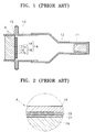
- a conventional laser-CRT includes a glass bulb 12 having an electron gun 11 emitting electron beams inserted therein, a connection ring 13 connected to an end of the glass bulb 12, a target portion 14 on which electron beams emitted from the electron gun 11 collide to generate a laser beam to form an image, and a support ring 15 in which the target portion 14 is installed, connected to the connection ring 13.
- the target portion 14 includes a single-crystal 16 for generating a laser beam when the electron beam is input, a resonator 18 composed of mirrors 17a and 17b formed on both sides of the single-crystal 16, and a disk 19 connected to one side of the resonator 18.
- the inside of the laser-CRT is maintained in a vacuum, and when the electron beams emitted from the electron gun 11 are accelerated toward the target portion 14 to collide against the single-crystal 16 of the resonator 18, the laser beams are generated, to thereby form an image.
- the temperature of the single-crystal 16 must be maintained at 80-200K to generate stable laser beams, so that the disk 19 formed of sapphire having excellent thermal emission is connected to one side of the resonator 18. Also, a refrigerant such as liquid nitrogen is supplied to the disk 19 to maintain the resonator 18 at a relatively low temperature.
- the junction between the disk 19 of a nonmetal and the support ring 15, is realized by a metalizing method in which a metal layer 21 containing Mo or Mn and a Cu-layer 22 are interposed therebetween. That is, in the above junction process, a paste having Mo and Mn as a main material is coated on a surface of the disk 19 and then the surface is dried to thereby form a metal layer 21.
- a glass component of the disk 19 reacts with Mn of the metal layer 21 to realize a junction between the metal layer 21 and the disk 19. Also, a Cu-layer 22 is formed between the metal layer 21 and the support ring 15 using a Cu welding material, to thereby connect the disk 19 to the support ring 15.
- the metal layer 21 and the Cu-layer 22 tend to be brittle. so that cracks or deformations occur at the junction portion between the support ring 15 and the disk 19, to thereby damage the vacuum state of the laser-CRT.
- a cathode ray tube comprises:
- the metal thin films comprise a Ti thin film and a Ni thin film.
- a method of manufacturing a laser cathode ray tube comprises the steps of:
- the metal thin films are heated in a vacuum state or in an atmosphere of an inert gas.
- a laser cathode ray tube of the present invention includes a glass bulb 32 within which an electron gun 31 for emitting electron beams is sealed, a connection ring 33 connected to an end of the glass bulb 32, a single-crystal 36 for generating laser beams when the electron beams are input, a target portion 34 composed of resonator 38 having mirrors 37a and 37b formed on both sides of the single-crystal 36 and a disk 39 connected to one side of the connection ring 33, and a support ring 35 in which the target portion 34 is installed, connected to the connection ring 33.
- the disk 39 is formed of sapphire having excellent heat emission.
- the support ring 35 is connected to the disk 39 by a junction layer 40 formed by pressurizing and heating at least two metal thin films.
- the junction layer 40 for example, is formed by pressurizing and heating Ti and Ni thin films of a predetermined thickness.
- the support ring 35 is formed of covar containing 29wt% Ni, 17wt% Co and Fe for the balance.
- FIGS. 4A through 4C A method of manufacturing a laser cathode ray tube having the above structure will be described with reference to FIGS. 4A through 4C.
- the same reference numerals refer to the same elements.
- the surface of the disk 39 is cleaned by trichloro-ethylene to remove foreign material attached to the surface of the disk 39, and then the disk 39 is spaced apart from the support ring 35 a predetermined distance as shown in FIG. 4A.
- first and second metal thin films 41 and 42 are disposed between the support ring 35 and the disk 39, and then the metal thin films are pressurized.
- the first and second metal thin films 41 and 42 are a Ti thin film and a Ni thin film.
- the Ti thin film and the Ni thin film have a thickness of 0.01 through 0.5 mm, and a purity of approximately 95 % or higher.
- a glass component may be added to the first and second metal thin films 41 and 42 to improve adhesion to the disk 39.
- the first and second metal thin films 41 and 42 between the support ring 35 and the disk 39 which have been pressurized are heated.
- the heating process is performed at approximately 1000°C or higher and in a vacuum state or in an inert gas atmosphere.
- the first and second metal thin films 41 and 42 are connected to each other by being pressurized and heated, to thereby form a junction layer 40, for instance, of Ti-Ni thin films between the support ring 35 and the disk 39.
- the support ring 35 and the disk are connected to each other due to formation of the junction layer 40.
- the junction layer 40 by the Ti-Ni thin films formed between the support ring 35 and the disk 39 have excellent intensity, particularly excellent mechanical characteristics even at a low temperature, to thereby increase the durability.
- the support ring and the disk having the Ti-Ni thin films interposed therebetween are pressurized and heated to be connected to each other, to thereby simplify the manufacturing process.
Landscapes
- Engineering & Computer Science (AREA)
- Manufacturing & Machinery (AREA)
- Lasers (AREA)
- Manufacture Of Electron Tubes, Discharge Lamp Vessels, Lead-In Wires, And The Like (AREA)
- Vessels, Lead-In Wires, Accessory Apparatuses For Cathode-Ray Tubes (AREA)
Applications Claiming Priority (2)
| Application Number | Priority Date | Filing Date | Title |
|---|---|---|---|
| KR1019970052357A KR100252066B1 (ko) | 1997-10-13 | 1997-10-13 | 레이저 음극선관 및 그 제조방법 |
| KR9752357 | 1997-10-13 |
Publications (1)
| Publication Number | Publication Date |
|---|---|
| EP0908918A1 true EP0908918A1 (de) | 1999-04-14 |
Family
ID=19522634
Family Applications (1)
| Application Number | Title | Priority Date | Filing Date |
|---|---|---|---|
| EP98308123A Withdrawn EP0908918A1 (de) | 1997-10-13 | 1998-10-06 | Laser- Kathodenstrahlröhre |
Country Status (4)
| Country | Link |
|---|---|
| US (1) | US6194825B1 (de) |
| EP (1) | EP0908918A1 (de) |
| JP (1) | JPH11163474A (de) |
| KR (1) | KR100252066B1 (de) |
Families Citing this family (4)
| Publication number | Priority date | Publication date | Assignee | Title |
|---|---|---|---|---|
| KR100522673B1 (ko) * | 1998-09-29 | 2006-01-27 | 삼성에스디아이 주식회사 | 레이저 음극선관 |
| KR100502316B1 (ko) * | 1998-09-30 | 2005-09-26 | 삼성에스디아이 주식회사 | 레이저 음극선관과 이의 제조 방법 |
| RU2000103497A (ru) * | 2000-02-09 | 2002-01-27 | Самсунг Дисплей Дивайсиз Ко. | Лазерный электронно-лучевой прибор |
| RU2391753C1 (ru) * | 2008-09-23 | 2010-06-10 | Общество с ограниченной ответственностью "Научно-производственная компания "ЭЛИТАР" | Лазерный электронно-лучевой прибор для генерации пикосекундных импульсов |
Citations (2)
| Publication number | Priority date | Publication date | Assignee | Title |
|---|---|---|---|---|
| FR2482366A1 (fr) * | 1980-05-06 | 1981-11-13 | Tokyo Shibaura Electric Co | Enveloppe sous vide pour un tube multiplicateur d'images de rayonnement, et son procede de fabrication |
| US5374870A (en) * | 1992-06-22 | 1994-12-20 | Principia Optics, Inc. | Laser screen cathode-ray tube with increased life span |
Family Cites Families (1)
| Publication number | Priority date | Publication date | Assignee | Title |
|---|---|---|---|---|
| US4650108A (en) * | 1985-08-15 | 1987-03-17 | The United States Of America As Represented By The Administrator Of The National Aeronautics And Space Administration | Method for forming hermetic seals |
-
1997
- 1997-10-13 KR KR1019970052357A patent/KR100252066B1/ko not_active Expired - Fee Related
-
1998
- 1998-09-30 JP JP10277769A patent/JPH11163474A/ja not_active Withdrawn
- 1998-10-06 EP EP98308123A patent/EP0908918A1/de not_active Withdrawn
- 1998-10-08 US US09/168,088 patent/US6194825B1/en not_active Expired - Fee Related
Patent Citations (2)
| Publication number | Priority date | Publication date | Assignee | Title |
|---|---|---|---|---|
| FR2482366A1 (fr) * | 1980-05-06 | 1981-11-13 | Tokyo Shibaura Electric Co | Enveloppe sous vide pour un tube multiplicateur d'images de rayonnement, et son procede de fabrication |
| US5374870A (en) * | 1992-06-22 | 1994-12-20 | Principia Optics, Inc. | Laser screen cathode-ray tube with increased life span |
Also Published As
| Publication number | Publication date |
|---|---|
| US6194825B1 (en) | 2001-02-27 |
| KR19990031576A (ko) | 1999-05-06 |
| JPH11163474A (ja) | 1999-06-18 |
| KR100252066B1 (ko) | 2000-04-15 |
Similar Documents
| Publication | Publication Date | Title |
|---|---|---|
| JP2001210258A (ja) | 画像表示装置およびその製造方法 | |
| US6140762A (en) | Wall assembly and method for attaching walls for flat panel displays | |
| US6194825B1 (en) | Laser cathode ray tube (laser-CRT) and method of manufacturing the same | |
| US5374870A (en) | Laser screen cathode-ray tube with increased life span | |
| US20050179360A1 (en) | Image display device, method of manufacturing image display device, and manufacturing apparatus | |
| KR100241598B1 (ko) | 음극선관용 결합스프링과 그 제조방법 | |
| KR100759136B1 (ko) | 화상 표시 장치 및 그 제조 방법 | |
| JP2000149791A (ja) | 封止容器及び封止方法及び封止装置及び画像形成装置 | |
| MXPA01009852A (es) | Tubo de imagenes a color que tiene una mascara de tension de expansion inferior unida a un marco de expansion mas alta. | |
| US6858982B2 (en) | Image display apparatus and method of manufacturing the same | |
| JPWO2006064880A1 (ja) | シール材、シール材を用いた画像表示装置、画像表示装置の製造方法、およびこの製造方法により製造された画像表示装置 | |
| KR20040054555A (ko) | 전자관 | |
| EP1705685A1 (de) | Bildanzeigeeinrichtung und verfahren zu ihrer herstellung | |
| KR100234169B1 (ko) | 레이저 음극선관 | |
| JP2001357803A (ja) | 画像表示装置およびその製造方法 | |
| JPH03245446A (ja) | X線管 | |
| US20060234594A1 (en) | Sealing material and image display device using sealing material | |
| EP1048048A1 (de) | Farbwahlelektrode für eine farbbildröhre | |
| KR100209632B1 (ko) | 브라운관의 산화 방지용 프리터블 게터구조 | |
| US6139388A (en) | Method of forming a frit seal between a stem and a neck of a cathode ray tube during manufacturing of a cathode ray tube | |
| JP4236561B2 (ja) | 蛍光表示管およびその金属材料 | |
| JP3524207B2 (ja) | カラー受像管の製造方法 | |
| JP2001189140A (ja) | 平面ブラウン管の防爆構造 | |
| US20050082975A1 (en) | Image display device and method of manufacturing the same | |
| JPH0822776A (ja) | カラー陰極線管 |
Legal Events
| Date | Code | Title | Description |
|---|---|---|---|
| PUAI | Public reference made under article 153(3) epc to a published international application that has entered the european phase |
Free format text: ORIGINAL CODE: 0009012 |
|
| AK | Designated contracting states |
Kind code of ref document: A1 Designated state(s): DE FR GB NL |
|
| AX | Request for extension of the european patent |
Free format text: AL;LT;LV;MK;RO;SI |
|
| 17P | Request for examination filed |
Effective date: 19990929 |
|
| AKX | Designation fees paid |
Free format text: DE FR GB NL |
|
| 17Q | First examination report despatched |
Effective date: 20010920 |
|
| GRAH | Despatch of communication of intention to grant a patent |
Free format text: ORIGINAL CODE: EPIDOS IGRA |
|
| STAA | Information on the status of an ep patent application or granted ep patent |
Free format text: STATUS: THE APPLICATION IS DEEMED TO BE WITHDRAWN |
|
| 18D | Application deemed to be withdrawn |
Effective date: 20030219 |