EP0908976A2 - Steckverbindersystem von hoher Dichte - Google Patents
Steckverbindersystem von hoher Dichte Download PDFInfo
- Publication number
- EP0908976A2 EP0908976A2 EP98118907A EP98118907A EP0908976A2 EP 0908976 A2 EP0908976 A2 EP 0908976A2 EP 98118907 A EP98118907 A EP 98118907A EP 98118907 A EP98118907 A EP 98118907A EP 0908976 A2 EP0908976 A2 EP 0908976A2
- Authority
- EP
- European Patent Office
- Prior art keywords
- contact elements
- circuit board
- connector
- elements
- frame
- Prior art date
- Legal status (The legal status is an assumption and is not a legal conclusion. Google has not performed a legal analysis and makes no representation as to the accuracy of the status listed.)
- Granted
Links
Images

Classifications
-
- H—ELECTRICITY
- H01—ELECTRIC ELEMENTS
- H01R—ELECTRICALLY-CONDUCTIVE CONNECTIONS; STRUCTURAL ASSOCIATIONS OF A PLURALITY OF MUTUALLY-INSULATED ELECTRICAL CONNECTING ELEMENTS; COUPLING DEVICES; CURRENT COLLECTORS
- H01R12/00—Structural associations of a plurality of mutually-insulated electrical connecting elements, specially adapted for printed circuits, e.g. printed circuit boards [PCB], flat or ribbon cables, or like generally planar structures, e.g. terminal strips, terminal blocks; Coupling devices specially adapted for printed circuits, flat or ribbon cables, or like generally planar structures; Terminals specially adapted for contact with, or insertion into, printed circuits, flat or ribbon cables, or like generally planar structures
- H01R12/70—Coupling devices
- H01R12/71—Coupling devices for rigid printing circuits or like structures
- H01R12/712—Coupling devices for rigid printing circuits or like structures co-operating with the surface of the printed circuit or with a coupling device exclusively provided on the surface of the printed circuit
- H01R12/716—Coupling device provided on the PCB
-
- H—ELECTRICITY
- H01—ELECTRIC ELEMENTS
- H01R—ELECTRICALLY-CONDUCTIVE CONNECTIONS; STRUCTURAL ASSOCIATIONS OF A PLURALITY OF MUTUALLY-INSULATED ELECTRICAL CONNECTING ELEMENTS; COUPLING DEVICES; CURRENT COLLECTORS
- H01R12/00—Structural associations of a plurality of mutually-insulated electrical connecting elements, specially adapted for printed circuits, e.g. printed circuit boards [PCB], flat or ribbon cables, or like generally planar structures, e.g. terminal strips, terminal blocks; Coupling devices specially adapted for printed circuits, flat or ribbon cables, or like generally planar structures; Terminals specially adapted for contact with, or insertion into, printed circuits, flat or ribbon cables, or like generally planar structures
- H01R12/70—Coupling devices
- H01R12/71—Coupling devices for rigid printing circuits or like structures
- H01R12/72—Coupling devices for rigid printing circuits or like structures coupling with the edge of the rigid printed circuits or like structures
- H01R12/722—Coupling devices for rigid printing circuits or like structures coupling with the edge of the rigid printed circuits or like structures coupling devices mounted on the edge of the printed circuits
- H01R12/724—Coupling devices for rigid printing circuits or like structures coupling with the edge of the rigid printed circuits or like structures coupling devices mounted on the edge of the printed circuits containing contact members forming a right angle
-
- H—ELECTRICITY
- H05—ELECTRIC TECHNIQUES NOT OTHERWISE PROVIDED FOR
- H05K—PRINTED CIRCUITS; CASINGS OR CONSTRUCTIONAL DETAILS OF ELECTRIC APPARATUS; MANUFACTURE OF ASSEMBLAGES OF ELECTRICAL COMPONENTS
- H05K3/00—Apparatus or processes for manufacturing printed circuits
- H05K3/30—Assembling printed circuits with electric components, e.g. with resistors
- H05K3/32—Assembling printed circuits with electric components, e.g. with resistors electrically connecting electric components or wires to printed circuits
- H05K3/34—Assembling printed circuits with electric components, e.g. with resistors electrically connecting electric components or wires to printed circuits by soldering
- H05K3/341—Surface mounted components
- H05K3/3421—Leaded components
- H05K3/3426—Leaded components characterised by the leads
Definitions
- the present invention relates to electrical connectors, and more particularly, to high density connectors intended for the interconnection of daughter boards and back panels.
- Density and pin count are often viewed interchangeably, but there are important differences. Density refers to the number of contacts provided per unit length. In contrast, the number of contact elements that can reasonably withstand the mating and unmating forces is referred to as the pin count. As more functions become integrated on semiconductor chips or on flexible circuit substrates and more chips are provided on printed circuit boards (PCBs), each PCB or flexible circuit must provide more inputs and outputs (I/Os). The demand for more I/Os directly translates to a demand for greater density without sacrificing electrical or mechanical performance, particularly when such devices and integration techniques are utilized in devices having back panels.
- I/Os inputs and outputs
- the daughterboard in back panel applications, the daughterboard is held in position, i.e., vertical and horizontal orientation, sometimes exclusively, by the connector used to electrically interconnect the two.
- Daughterboard size, the number of daughterboards and the components mounted to the daughterboards combine to produce the stresses and moments acting on the back panel after assembly. If the amount of back panel material is reduced in particular locations due to larger numbers of closely spaced through bores, back panel failure can occur, i.e., the back panel could deform or even break.
- Surface mount techniques typically involve temporarily fixing a component to a printed circuit board using a paste. After pasting, the board and temporarily fixed components are heated in order to reflow solder material previously coated onto the leads of the surface mount components.
- numerous connectors are attached to the back panel board, which is typically a relatively large circuit board.
- the back panel board In order to assure adequate reflow, thereby establishing good electrical connection, for numerous components spread over a relatively large board, the back panel board would have to be subjected to significant heat. Unfortunately, heat which is too high or too long in duration can actually interfere with establishing good surface mount terminations. Consequently, surface mount techniques do not form the answer to the need for higher density connectors for back panel applications.
- the connector includes a base member having a plurality of bores.
- a first plurality of contact elements is positioned in certain of the bores.
- a second plurality of contact elements is positioned in others of the bores.
- the tail portion of each contact element extends a distance beyond the base member. The insertion of the tail portion of the second plurality of contact elements into circuit board through bores is sufficient to hold the tail portions of the first plurality of contact elements against the circuit board.
- the tail portions of the first plurality of contacts prefferably be capable of axial movement when a compression force is applied.
- the connector in another embodiment, includes a frame and a layer of contact elements, attached to the frame.
- Each of the contact elements includes a receiving portion and a tail portion.
- the ends of the tail portions are positioned proximate the bottom surface of the frame.
- a plurality of fusible elements for example, solder balls, are located proximate the ends of the tail portions.
- the solder balls extend within a desired distance from the base. This result is achieved by using solder balls having a deformed spherical shape. It is especially preferred for the deformed spherical shape to have a flattened bottom surface.
- the solder balls are attached to the bottom of the frame for keying and spacing said frame in relation to a printed circuit board.
- the solder balls it is again preferred for the solder balls to have a deformed spherical shape, wherein the deformed spherical shape is flattened, i.e., the aspect ratio of the solder ball includes greater length than height.
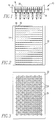
- FIG. 1 is a top view of plug 10.
- Connectors constructed in accordance with the invention have the advantage of requiring only half the pins having through holes while the other half utilizes contact pads for establishing electrical connection. In back panel applications, such a construction preserves the mechanical integrity of the back panel while providing a significantly higher pin density.
- Figure 3 depicts the portion of printed circuit board 22 onto which plug 10 is to be mounted. Circuit board 22 includes a pattern of bores 24 and contact pads 26. It is noted that the diameter of the contact pad is smaller than the diameter of the bore and that the bores and contact pads are arranged in an alternating pattern.
- the tail portions of blades 18 When plug 10 is mounted to circuit board 22, the tail portions of blades 18 are inserted into bores 24. The force of insertion causes the compressible end portions of blade 20 to establish electrical contact with pads 26. It is preferred for the tail portions of blades 18 to be either deformable or of a shape to cause a friction force between the tail portion and circuit board 22 sufficient to hold plug 10 in place and maintain electrical contact between the tail portions of blades 20 and contact pads 26.
- connector 30 constructed in accordance with the present invention will be described. Although depicted as a receptacle, it will be appreciated that the invention is applicable to either a plug or receptacle.
- Connector 30 is shown diagrammatically to include a number of contact elements 32. It is noted that the contact elements are oriented in generally the same plane and are preferably provided as layer modules. Assembly of receptacle 30, thereby requires the stacking of a number of layers of contact elements in a side by side relationship. As shown in Figure 5, each layer of contact elements includes a positioning frame 34 formed from upstanding portion 36 and base portion 38. It may be desirable during manufacture, to integrally mold portions 36 and 38 to a series of contact elements 32, thereby forming a contact element module.
- the receptacle of the present invention includes a novel structure for establishing electrical contact between module 30 and circuit board 40.
- the present invention utilizes fusible elements, for example, solder balls for mounting module 30 to board 40. Because module 30 is a high density module, the use of solder balls will be sufficient to establish both electrical contact as well as providing sufficient mechanical force for maintaining the attachment of module 30. To this end, a pattern of contact pads (not shown) are disposed on the surface of circuit board 40.
- a keying peg 44 is provided on base portion 38 for aligning the tail ends of contact elements 32 above individual contact pads. Shoulder 46 and leg 48 serve to space the bottom of base portion 38 from the top of circuit board 40. It may be desirable to precisely fix this distance. As will be explained in greater detail in relation to Figures 6-8, contact elements 32 are electrically connected to contact pads (not shown) on the surface of circuit board 40 through the use of solder balls.
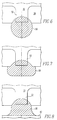
- a fusible element for example, solder ball 50 is shown attached to end 52.
- Attachment of solder ball 50 can be by any suitable means, for example by reflowing techniques. It is noted that the bottom surface of base 38 extends a short distance beyond the end surface of end 52. In other words, the end surface of end 52 is recessed within base portion 38. After attachment of solder ball 50 to end 52 the solder ball extends beyond the bottom surface of base portion 38.
- solder balls permits high density connection without through bores, one problem still remains. Because the solder balls extend beyond the bottom surface of base portion 38, connector 30 may be suspended a short distance above the circuit board when the connector is assembled onto a circuit board. In such a situation, when solder balls 50 are reflowed in order to establish electrical connection with the contact pads (not shown), movement, i.e., re-alignment, of module 30 will occur. Such re-alignment can cause insertion force to rise to unacceptable levels. This problem has been largely overcome by the present invention.
- the fusible elements are deformed to yield an aspect ratio in which length (the dimension parallel to the circuit board to which the connector is to be mounted) is greater than the height (the dimension parallel to a line from the point of attachment to the circuit board to the frame).
- the aspect ratio of the fusible element is greater than one.
- the fusible element or solder ball is wider than it is high.
- the fusible elements such as solder balls
- the deformation process can include either fixing the frame and pressing or striking a platen-like device (not shown) against the bottom surface of each solder ball or by pressing each solder ball against an anvil-like device. In either case, the solder ball is preferably deformed to have a flattened shape.
- the fusible elements are placed near the ends or terminal stubs of the contact elements and subjected to heat in order to cause reflow to occur. Reflow will cause the fusible elements to become attached to the terminal stubs. Thereafter, the fusible elements are deformed.
- the deformation process can include either fixing the frame and pressing or striking a platen-like device against the bottom surface of each fusible element or by pressing each solder ball against an anvil-like device. In either case, the fusible elements are again preferably deformed to have a flattened shape.
- solder balls are used as the fusible element. After manufacturing it is probable that the ends of the solder balls may extend beyond the spacing distance established by shoulder 46 and leg 48. In other words when the connector is placed onto the circuit board it may initially be supported by certain of the solder balls rather than shoulder 46 and leg 48. When the solder melts, as during during reflow, the connector will physically move towards the circuit board, thereby realigning the connector. When flattened or deformed (aspect ration greater than 1) solder balls are used, the connector moves a shorter distance. Accordingly, the opportunity for misalignment is significantly less, because, prior to reflow, the connector is in a position closer to the desired position in three dimensions (x, y and z). Having the connector positioned as close to the ultimate z position as possible, prior to reflow, is most critical.
- solder ball 50 has been deformed, preferably by exerting a compression force on the solder ball.
- the exertion of such a compression force deforms the solder ball out of a spherical shape to preferably having a flattened bottom shape, i.e., an aspect ration greater than one.
- solder ball 50 is reflowed, it returns to a spherical shape eliminating the collapsed or deformed shape and changing the elevation of the connector.
- An example of such a reflowed solder ball is shown in Figure 8.
- solder ball 50 after reflow, has extended a distance such that electrical contact is now made between circuit board 40 and end 52 of contact element 32.
Landscapes
- Coupling Device And Connection With Printed Circuit (AREA)
- Multi-Conductor Connections (AREA)
Priority Applications (1)
| Application Number | Priority Date | Filing Date | Title |
|---|---|---|---|
| EP02007340A EP1229607B1 (de) | 1997-10-10 | 1998-10-07 | Steckverbindersystem von hoher Dichte |
Applications Claiming Priority (2)
| Application Number | Priority Date | Filing Date | Title |
|---|---|---|---|
| US08/948,751 US5975921A (en) | 1997-10-10 | 1997-10-10 | High density connector system |
| US948751 | 1997-10-10 |
Related Child Applications (1)
| Application Number | Title | Priority Date | Filing Date |
|---|---|---|---|
| EP02007340A Division EP1229607B1 (de) | 1997-10-10 | 1998-10-07 | Steckverbindersystem von hoher Dichte |
Publications (3)
| Publication Number | Publication Date |
|---|---|
| EP0908976A2 true EP0908976A2 (de) | 1999-04-14 |
| EP0908976A3 EP0908976A3 (de) | 1999-12-01 |
| EP0908976B1 EP0908976B1 (de) | 2003-02-12 |
Family
ID=25488224
Family Applications (2)
| Application Number | Title | Priority Date | Filing Date |
|---|---|---|---|
| EP98118907A Expired - Lifetime EP0908976B1 (de) | 1997-10-10 | 1998-10-07 | Steckverbindersystem von hoher Dichte |
| EP02007340A Expired - Lifetime EP1229607B1 (de) | 1997-10-10 | 1998-10-07 | Steckverbindersystem von hoher Dichte |
Family Applications After (1)
| Application Number | Title | Priority Date | Filing Date |
|---|---|---|---|
| EP02007340A Expired - Lifetime EP1229607B1 (de) | 1997-10-10 | 1998-10-07 | Steckverbindersystem von hoher Dichte |
Country Status (7)
| Country | Link |
|---|---|
| US (2) | US5975921A (de) |
| EP (2) | EP0908976B1 (de) |
| JP (2) | JP4294767B2 (de) |
| CN (2) | CN1275355C (de) |
| DE (2) | DE69823890T2 (de) |
| SG (2) | SG101433A1 (de) |
| TW (1) | TW411061U (de) |
Families Citing this family (54)
| Publication number | Priority date | Publication date | Assignee | Title |
|---|---|---|---|---|
| US6267603B1 (en) * | 1998-04-01 | 2001-07-31 | Molex Incorporated | Burn-in test socket |
| TW399789U (en) * | 1999-02-02 | 2000-07-21 | Hon Hai Prec Ind Co Ltd | Electrical connector |
| US6349037B1 (en) * | 1999-05-04 | 2002-02-19 | International Business Machines Corporation | Backplane for common building block |
| US6869292B2 (en) * | 2001-07-31 | 2005-03-22 | Fci Americas Technology, Inc. | Modular mezzanine connector |
| US6699048B2 (en) * | 2002-01-14 | 2004-03-02 | Fci Americas Technology, Inc. | High density connector |
| US6719567B2 (en) * | 2002-05-20 | 2004-04-13 | Hon Hai Precision Ind. Co., Ltd. | Contact for electrical connector |
| US20040147169A1 (en) | 2003-01-28 | 2004-07-29 | Allison Jeffrey W. | Power connector with safety feature |
| TWI264150B (en) * | 2003-04-22 | 2006-10-11 | Starlink Electronics Corp | High-density electrical connector |
| US7458839B2 (en) | 2006-02-21 | 2008-12-02 | Fci Americas Technology, Inc. | Electrical connectors having power contacts with alignment and/or restraining features |
| CN101882718B (zh) | 2003-12-31 | 2012-11-21 | Fci公司 | 电源触头及包括电源触头的连接器 |
| SG122809A1 (en) * | 2003-12-31 | 2006-06-29 | Fci Asia Technology Pte Ltd | Electrical connector |
| US7214104B2 (en) | 2004-09-14 | 2007-05-08 | Fci Americas Technology, Inc. | Ball grid array connector |
| US7476108B2 (en) | 2004-12-22 | 2009-01-13 | Fci Americas Technology, Inc. | Electrical power connectors with cooling features |
| US7226296B2 (en) * | 2004-12-23 | 2007-06-05 | Fci Americas Technology, Inc. | Ball grid array contacts with spring action |
| US20060148283A1 (en) * | 2004-12-30 | 2006-07-06 | Minich Steven E | Surface-mount electrical connector with strain-relief features |
| US7384289B2 (en) | 2005-01-31 | 2008-06-10 | Fci Americas Technology, Inc. | Surface-mount connector |
| US7303427B2 (en) | 2005-04-05 | 2007-12-04 | Fci Americas Technology, Inc. | Electrical connector with air-circulation features |
| US7425145B2 (en) | 2006-05-26 | 2008-09-16 | Fci Americas Technology, Inc. | Connectors and contacts for transmitting electrical power |
| US7726982B2 (en) | 2006-06-15 | 2010-06-01 | Fci Americas Technology, Inc. | Electrical connectors with air-circulation features |
| US7661997B2 (en) * | 2006-09-12 | 2010-02-16 | Woody Wurster | Pin to CB system |
| US7497736B2 (en) | 2006-12-19 | 2009-03-03 | Fci Americas Technology, Inc. | Shieldless, high-speed, low-cross-talk electrical connector |
| US7641500B2 (en) | 2007-04-04 | 2010-01-05 | Fci Americas Technology, Inc. | Power cable connector system |
| US7905731B2 (en) | 2007-05-21 | 2011-03-15 | Fci Americas Technology, Inc. | Electrical connector with stress-distribution features |
| US7762857B2 (en) | 2007-10-01 | 2010-07-27 | Fci Americas Technology, Inc. | Power connectors with contact-retention features |
| US8272882B2 (en) * | 2007-12-27 | 2012-09-25 | Yamaichi Electronics Co., Ltd. | Semiconductor device socket |
| US8062051B2 (en) | 2008-07-29 | 2011-11-22 | Fci Americas Technology Llc | Electrical communication system having latching and strain relief features |
| USD606497S1 (en) | 2009-01-16 | 2009-12-22 | Fci Americas Technology, Inc. | Vertical electrical connector |
| USD608293S1 (en) | 2009-01-16 | 2010-01-19 | Fci Americas Technology, Inc. | Vertical electrical connector |
| USD606496S1 (en) | 2009-01-16 | 2009-12-22 | Fci Americas Technology, Inc. | Right-angle electrical connector |
| USD610548S1 (en) | 2009-01-16 | 2010-02-23 | Fci Americas Technology, Inc. | Right-angle electrical connector |
| USD640637S1 (en) | 2009-01-16 | 2011-06-28 | Fci Americas Technology Llc | Vertical electrical connector |
| USD664096S1 (en) | 2009-01-16 | 2012-07-24 | Fci Americas Technology Llc | Vertical electrical connector |
| USD619099S1 (en) | 2009-01-30 | 2010-07-06 | Fci Americas Technology, Inc. | Electrical connector |
| US8323049B2 (en) | 2009-01-30 | 2012-12-04 | Fci Americas Technology Llc | Electrical connector having power contacts |
| JP5630989B2 (ja) | 2009-03-11 | 2014-11-26 | 花王株式会社 | 二剤式染毛剤 |
| US8366485B2 (en) | 2009-03-19 | 2013-02-05 | Fci Americas Technology Llc | Electrical connector having ribbed ground plate |
| USD618181S1 (en) | 2009-04-03 | 2010-06-22 | Fci Americas Technology, Inc. | Asymmetrical electrical connector |
| USD618180S1 (en) | 2009-04-03 | 2010-06-22 | Fci Americas Technology, Inc. | Asymmetrical electrical connector |
| JP2012018892A (ja) * | 2010-07-09 | 2012-01-26 | Tyco Electronics Japan Kk | 電気部品 |
| JP5869282B2 (ja) * | 2011-10-03 | 2016-02-24 | タイコエレクトロニクスジャパン合同会社 | 電気コネクタ |
| EP2624034A1 (de) | 2012-01-31 | 2013-08-07 | Fci | Abbaubare optische Kupplungsvorrichtung |
| USD718253S1 (en) | 2012-04-13 | 2014-11-25 | Fci Americas Technology Llc | Electrical cable connector |
| USD727268S1 (en) | 2012-04-13 | 2015-04-21 | Fci Americas Technology Llc | Vertical electrical connector |
| US8944831B2 (en) | 2012-04-13 | 2015-02-03 | Fci Americas Technology Llc | Electrical connector having ribbed ground plate with engagement members |
| USD727852S1 (en) | 2012-04-13 | 2015-04-28 | Fci Americas Technology Llc | Ground shield for a right angle electrical connector |
| US9257778B2 (en) | 2012-04-13 | 2016-02-09 | Fci Americas Technology | High speed electrical connector |
| USD751507S1 (en) | 2012-07-11 | 2016-03-15 | Fci Americas Technology Llc | Electrical connector |
| US9543703B2 (en) | 2012-07-11 | 2017-01-10 | Fci Americas Technology Llc | Electrical connector with reduced stack height |
| JP5454646B1 (ja) * | 2012-09-25 | 2014-03-26 | 第一精工株式会社 | 電気コネクタ |
| USD745852S1 (en) | 2013-01-25 | 2015-12-22 | Fci Americas Technology Llc | Electrical connector |
| USD720698S1 (en) | 2013-03-15 | 2015-01-06 | Fci Americas Technology Llc | Electrical cable connector |
| US10170876B2 (en) * | 2016-10-05 | 2019-01-01 | Schlumberger Technology Corporation | Electrical connectors having a plurality of pins and sockets |
| EP3312838A1 (de) | 2016-10-18 | 2018-04-25 | Fraunhofer Gesellschaft zur Förderung der Angewand | Vorrichtung und verfahren zur verarbeitung eines audiosignals |
| JP2019114409A (ja) * | 2017-12-22 | 2019-07-11 | 富士通株式会社 | 表面実装型コネクタ、及び表面実装基板の製造方法 |
Family Cites Families (47)
| Publication number | Priority date | Publication date | Assignee | Title |
|---|---|---|---|---|
| US32691A (en) * | 1861-07-02 | Stove | ||
| US4396140A (en) | 1981-01-27 | 1983-08-02 | Bell Telephone Laboratories, Incorporated | Method of bonding electronic components |
| USRE32691E (en) | 1982-08-23 | 1988-06-07 | Amp Incorporated | High speed modular connector for printed circuit boards |
| JPS60131948U (ja) * | 1984-02-13 | 1985-09-03 | 双葉電子工業株式会社 | 蛍光表示管 |
| US4678250A (en) * | 1985-01-08 | 1987-07-07 | Methode Electronics, Inc. | Multi-pin electrical header |
| DE3779971T2 (de) * | 1986-07-10 | 1993-02-04 | Amp Inc | Verbinder fuer eine gedruckte leiterplatte. |
| US4722470A (en) * | 1986-12-01 | 1988-02-02 | International Business Machines Corporation | Method and transfer plate for applying solder to component leads |
| US4826442A (en) * | 1986-12-19 | 1989-05-02 | Amp Incorporated | Solderable connector retention feature |
| JPS63269466A (ja) * | 1987-04-27 | 1988-11-07 | Nippon Telegr & Teleph Corp <Ntt> | 印刷配線板用電気コネクタ |
| US4846734A (en) * | 1988-01-22 | 1989-07-11 | Burndy Corporation | Vertical edge card connectors |
| US4846727A (en) * | 1988-04-11 | 1989-07-11 | Amp Incorporated | Reference conductor for improving signal integrity in electrical connectors |
| US4956913A (en) * | 1988-05-11 | 1990-09-18 | E. I. Du Pont De Nemours And Company | Pin alignment method |
| GB8819435D0 (en) * | 1988-08-16 | 1988-09-21 | Bicc Plc | Electrical connector |
| US4975084A (en) * | 1988-10-17 | 1990-12-04 | Amp Incorporated | Electrical connector system |
| DE69018000T2 (de) * | 1989-10-10 | 1995-09-28 | Whitaker Corp | Rückwandsteckverbinder mit angepasster Impedanz. |
| US4971565A (en) * | 1989-11-28 | 1990-11-20 | Fox Jr Roy W | Surface mount stacking connector |
| US4978308A (en) * | 1989-12-18 | 1990-12-18 | Amp Incorporated | Surface mount pin header |
| GB8928777D0 (en) * | 1989-12-20 | 1990-02-28 | Amp Holland | Sheilded backplane connector |
| US5261829A (en) * | 1990-06-08 | 1993-11-16 | Fusselman David F | Connectors with ground structure |
| US5046966A (en) * | 1990-10-05 | 1991-09-10 | International Business Machines Corporation | Coaxial cable connector assembly |
| US5046960A (en) * | 1990-12-20 | 1991-09-10 | Amp Incorporated | High density connector system |
| JP2892514B2 (ja) * | 1991-01-22 | 1999-05-17 | ケル株式会社 | 電気コネクタ |
| US5178549A (en) * | 1991-06-27 | 1993-01-12 | Cray Research, Inc. | Shielded connector block |
| JP3014503B2 (ja) * | 1991-08-05 | 2000-02-28 | 日本特殊陶業株式会社 | 集積回路用パッケージ |
| US5261155A (en) * | 1991-08-12 | 1993-11-16 | International Business Machines Corporation | Method for bonding flexible circuit to circuitized substrate to provide electrical connection therebetween using different solders |
| US5192228A (en) * | 1991-09-16 | 1993-03-09 | Amp Inc. | Shielded surface mount electrical connector with integral barbed board lock |
| US5162001A (en) * | 1991-11-13 | 1992-11-10 | Molex Incorporated | Shielded electrical connector |
| US5174764A (en) * | 1991-12-20 | 1992-12-29 | Amp Incorporated | Connector assembly having surface mounted terminals |
| DE4143006A1 (de) * | 1991-12-24 | 1993-07-01 | Minnesota Mining & Mfg | Kontaktanordnung fuer ein elektrisches bauteil und verfahren zur herstellung |
| GB9205088D0 (en) * | 1992-03-09 | 1992-04-22 | Amp Holland | Shielded back plane connector |
| GB9205087D0 (en) * | 1992-03-09 | 1992-04-22 | Amp Holland | Sheilded back plane connector |
| JP3338527B2 (ja) | 1992-10-07 | 2002-10-28 | 富士通株式会社 | 高密度積層形のコネクタ、及び、コネクタの設計方法 |
| US5403206A (en) * | 1993-04-05 | 1995-04-04 | Teradyne, Inc. | Shielded electrical connector |
| GB9307127D0 (en) * | 1993-04-06 | 1993-05-26 | Amp Holland | Prestressed shielding plates for electrical connectors |
| JP3355353B2 (ja) * | 1993-08-20 | 2002-12-09 | ケル株式会社 | 電気コネクタ |
| US5358417A (en) * | 1993-08-27 | 1994-10-25 | The Whitaker Corporation | Surface mountable electrical connector |
| US5413491A (en) * | 1993-10-13 | 1995-05-09 | Burndy Corporation | Small form factor connectors with center ground plate |
| JPH07142489A (ja) | 1993-11-17 | 1995-06-02 | Matsushita Electric Ind Co Ltd | バンプの形成方法 |
| US5615824A (en) * | 1994-06-07 | 1997-04-01 | Tessera, Inc. | Soldering with resilient contacts |
| US5562462A (en) * | 1994-07-19 | 1996-10-08 | Matsuba; Stanley | Reduced crosstalk and shielded adapter for mounting an integrated chip package on a circuit board like member |
| US5477933A (en) * | 1994-10-24 | 1995-12-26 | At&T Corp. | Electronic device interconnection techniques |
| US5585162A (en) * | 1995-06-16 | 1996-12-17 | Minnesota Mining And Manufacturing Company | Ground plane routing |
| JP3074456B2 (ja) * | 1995-08-15 | 2000-08-07 | 日本航空電子工業株式会社 | 表面実装用端子 |
| WO1997013295A1 (en) * | 1995-10-06 | 1997-04-10 | The Whitaker Corporation | Connector and manufacturing method therefor |
| JP3346695B2 (ja) * | 1996-02-23 | 2002-11-18 | 京セラ株式会社 | 半導体素子収納用パッケージの製造方法 |
| US5735697A (en) * | 1996-09-27 | 1998-04-07 | Itt Corporation | Surface mount connector |
| US6139336A (en) * | 1996-11-14 | 2000-10-31 | Berg Technology, Inc. | High density connector having a ball type of contact surface |
-
1997
- 1997-10-10 US US08/948,751 patent/US5975921A/en not_active Expired - Lifetime
-
1998
- 1998-09-24 TW TW087215887U patent/TW411061U/zh not_active IP Right Cessation
- 1998-10-01 SG SG200006956A patent/SG101433A1/en unknown
- 1998-10-01 SG SG1998003958A patent/SG77201A1/en unknown
- 1998-10-07 EP EP98118907A patent/EP0908976B1/de not_active Expired - Lifetime
- 1998-10-07 DE DE69823890T patent/DE69823890T2/de not_active Expired - Lifetime
- 1998-10-07 EP EP02007340A patent/EP1229607B1/de not_active Expired - Lifetime
- 1998-10-07 DE DE69811307T patent/DE69811307T2/de not_active Expired - Lifetime
- 1998-10-09 CN CN02142868.9A patent/CN1275355C/zh not_active Expired - Fee Related
- 1998-10-09 CN CNB981197957A patent/CN1155139C/zh not_active Expired - Fee Related
- 1998-10-12 JP JP28988598A patent/JP4294767B2/ja not_active Expired - Lifetime
-
1999
- 1999-08-18 US US09/376,850 patent/US6241536B1/en not_active Expired - Lifetime
-
2008
- 2008-08-12 JP JP2008207987A patent/JP4950144B2/ja not_active Expired - Lifetime
Also Published As
| Publication number | Publication date |
|---|---|
| JP4950144B2 (ja) | 2012-06-13 |
| JPH11191447A (ja) | 1999-07-13 |
| CN1214557A (zh) | 1999-04-21 |
| DE69823890D1 (de) | 2004-06-17 |
| SG77201A1 (en) | 2000-12-19 |
| SG101433A1 (en) | 2004-01-30 |
| EP1229607A1 (de) | 2002-08-07 |
| EP1229607B1 (de) | 2004-05-12 |
| JP4294767B2 (ja) | 2009-07-15 |
| DE69811307T2 (de) | 2003-11-20 |
| CN1155139C (zh) | 2004-06-23 |
| US6241536B1 (en) | 2001-06-05 |
| JP2008300365A (ja) | 2008-12-11 |
| TW411061U (en) | 2000-11-01 |
| EP0908976A3 (de) | 1999-12-01 |
| CN1503408A (zh) | 2004-06-09 |
| CN1275355C (zh) | 2006-09-13 |
| US5975921A (en) | 1999-11-02 |
| EP0908976B1 (de) | 2003-02-12 |
| DE69811307D1 (de) | 2003-03-20 |
| DE69823890T2 (de) | 2005-04-21 |
Similar Documents
| Publication | Publication Date | Title |
|---|---|---|
| EP0908976B1 (de) | Steckverbindersystem von hoher Dichte | |
| US5593322A (en) | Leadless high density connector | |
| CN102394398B (zh) | 具有配合配接器的连接器组件 | |
| US7874847B2 (en) | Electronic part and circuit substrate | |
| US7837477B2 (en) | Electrical interconnection devices incorporating Fedundant contact points for reducing capacitive stubs and improved signal integrity | |
| US6544045B1 (en) | Surface mounted right angle electrical connector | |
| US5210939A (en) | Lead grid array integrated circuit | |
| JP3396833B2 (ja) | 電子相互接続装置およびその作成方法 | |
| US6821144B2 (en) | Densely arranged duplex profile connector assembly | |
| US7179091B2 (en) | Edge mount electrical connector | |
| US20020102869A1 (en) | Surface mount atttachable land grid array connector and method of forming same | |
| EP1150390B1 (de) | Modularer elektrischer Verbinder | |
| EP0693796A1 (de) | Verbinder mit Metallstreifen als Kontakte, und Verbinderanordnung mit diesen | |
| US6666693B2 (en) | Surface-mounted right-angle electrical connector | |
| US20220354013A1 (en) | Socket alignment and retention system | |
| US20050221680A1 (en) | Electrical interconnection devices incorporating redundant contact points for reducing capacitive stubs and improved signal integrity | |
| US6723927B1 (en) | High-reliability interposer for low cost and high reliability applications | |
| GB2325354A (en) | Electrical connector or connection with concave ball-receiving site | |
| US4834662A (en) | Method and arrangement for the connection of a multipole connector to a circuit board | |
| EP1109265B1 (de) | Elektrisches Verbindergehäuse | |
| EP0694996A1 (de) | Partiell metallisierter, aus Kunststoff geformter Verbinder mit "hold-down" Befestigung | |
| KR100545966B1 (ko) | 고밀도 커넥터 시스템 | |
| CN111384609B (zh) | 芯片与背板连接器互连装置 |
Legal Events
| Date | Code | Title | Description |
|---|---|---|---|
| PUAI | Public reference made under article 153(3) epc to a published international application that has entered the european phase |
Free format text: ORIGINAL CODE: 0009012 |
|
| AK | Designated contracting states |
Kind code of ref document: A2 Designated state(s): BE DE FI FR GB IT NL SE |
|
| AX | Request for extension of the european patent |
Free format text: AL;LT;LV;MK;RO;SI |
|
| PUAL | Search report despatched |
Free format text: ORIGINAL CODE: 0009013 |
|
| AK | Designated contracting states |
Kind code of ref document: A3 Designated state(s): AT BE CH CY DE DK ES FI FR GB GR IE IT LI LU MC NL PT SE |
|
| AX | Request for extension of the european patent |
Free format text: AL;LT;LV;MK;RO;SI |
|
| 17P | Request for examination filed |
Effective date: 20000406 |
|
| AKX | Designation fees paid |
Free format text: BE DE FI FR GB IT NL SE |
|
| 17Q | First examination report despatched |
Effective date: 20001031 |
|
| RIC1 | Information provided on ipc code assigned before grant |
Free format text: 7H 01R 12/18 A, 7H 01R 12/20 B, 7H 01R 12/22 B |
|
| RIC1 | Information provided on ipc code assigned before grant |
Free format text: 7H 01R 12/18 A, 7H 01R 12/20 B, 7H 01R 12/22 B |
|
| GRAG | Despatch of communication of intention to grant |
Free format text: ORIGINAL CODE: EPIDOS AGRA |
|
| GRAG | Despatch of communication of intention to grant |
Free format text: ORIGINAL CODE: EPIDOS AGRA |
|
| GRAH | Despatch of communication of intention to grant a patent |
Free format text: ORIGINAL CODE: EPIDOS IGRA |
|
| GRAH | Despatch of communication of intention to grant a patent |
Free format text: ORIGINAL CODE: EPIDOS IGRA |
|
| GRAA | (expected) grant |
Free format text: ORIGINAL CODE: 0009210 |
|
| AK | Designated contracting states |
Designated state(s): BE DE FI FR GB IT NL SE |
|
| REG | Reference to a national code |
Ref country code: GB Ref legal event code: FG4D |
|
| REF | Corresponds to: |
Ref document number: 69811307 Country of ref document: DE Date of ref document: 20030320 Kind code of ref document: P |
|
| ET | Fr: translation filed | ||
| PLBE | No opposition filed within time limit |
Free format text: ORIGINAL CODE: 0009261 |
|
| STAA | Information on the status of an ep patent application or granted ep patent |
Free format text: STATUS: NO OPPOSITION FILED WITHIN TIME LIMIT |
|
| 26N | No opposition filed |
Effective date: 20031113 |
|
| REG | Reference to a national code |
Ref country code: FR Ref legal event code: TP Ref country code: FR Ref legal event code: CD Ref country code: FR Ref legal event code: CA |
|
| REG | Reference to a national code |
Ref country code: GB Ref legal event code: 732E Free format text: REGISTERED BETWEEN 20111208 AND 20111214 |
|
| REG | Reference to a national code |
Ref country code: FR Ref legal event code: PLFP Year of fee payment: 18 |
|
| PGFP | Annual fee paid to national office [announced via postgrant information from national office to epo] |
Ref country code: GB Payment date: 20150924 Year of fee payment: 18 |
|
| PGFP | Annual fee paid to national office [announced via postgrant information from national office to epo] |
Ref country code: FR Payment date: 20150924 Year of fee payment: 18 |
|
| PGFP | Annual fee paid to national office [announced via postgrant information from national office to epo] |
Ref country code: FI Payment date: 20151002 Year of fee payment: 18 Ref country code: IT Payment date: 20151016 Year of fee payment: 18 Ref country code: DE Payment date: 20151030 Year of fee payment: 18 |
|
| PGFP | Annual fee paid to national office [announced via postgrant information from national office to epo] |
Ref country code: NL Payment date: 20151007 Year of fee payment: 18 Ref country code: BE Payment date: 20151009 Year of fee payment: 18 |
|
| PG25 | Lapsed in a contracting state [announced via postgrant information from national office to epo] |
Ref country code: BE Free format text: LAPSE BECAUSE OF NON-PAYMENT OF DUE FEES Effective date: 20161031 |
|
| REG | Reference to a national code |
Ref country code: DE Ref legal event code: R119 Ref document number: 69811307 Country of ref document: DE |
|
| REG | Reference to a national code |
Ref country code: NL Ref legal event code: MM Effective date: 20161101 |
|
| GBPC | Gb: european patent ceased through non-payment of renewal fee |
Effective date: 20161007 |
|
| REG | Reference to a national code |
Ref country code: FR Ref legal event code: ST Effective date: 20170630 |
|
| PG25 | Lapsed in a contracting state [announced via postgrant information from national office to epo] |
Ref country code: FI Free format text: LAPSE BECAUSE OF NON-PAYMENT OF DUE FEES Effective date: 20161007 Ref country code: DE Free format text: LAPSE BECAUSE OF NON-PAYMENT OF DUE FEES Effective date: 20170503 Ref country code: GB Free format text: LAPSE BECAUSE OF NON-PAYMENT OF DUE FEES Effective date: 20161007 Ref country code: FR Free format text: LAPSE BECAUSE OF NON-PAYMENT OF DUE FEES Effective date: 20161102 |
|
| PG25 | Lapsed in a contracting state [announced via postgrant information from national office to epo] |
Ref country code: NL Free format text: LAPSE BECAUSE OF NON-PAYMENT OF DUE FEES Effective date: 20161101 |
|
| PGFP | Annual fee paid to national office [announced via postgrant information from national office to epo] |
Ref country code: SE Payment date: 20170407 Year of fee payment: 19 |
|
| PG25 | Lapsed in a contracting state [announced via postgrant information from national office to epo] |
Ref country code: IT Free format text: LAPSE BECAUSE OF NON-PAYMENT OF DUE FEES Effective date: 20161007 |
|
| REG | Reference to a national code |
Ref country code: BE Ref legal event code: MM Effective date: 20161031 |
|
| REG | Reference to a national code |
Ref country code: SE Ref legal event code: EUG |
|
| PG25 | Lapsed in a contracting state [announced via postgrant information from national office to epo] |
Ref country code: SE Free format text: LAPSE BECAUSE OF NON-PAYMENT OF DUE FEES Effective date: 20171008 |