EP0909029B1 - Méthode d'adaptation des coefficients de filtrage et dispositif de filtrage numérique adaptatif - Google Patents
Méthode d'adaptation des coefficients de filtrage et dispositif de filtrage numérique adaptatif Download PDFInfo
- Publication number
- EP0909029B1 EP0909029B1 EP19980117149 EP98117149A EP0909029B1 EP 0909029 B1 EP0909029 B1 EP 0909029B1 EP 19980117149 EP19980117149 EP 19980117149 EP 98117149 A EP98117149 A EP 98117149A EP 0909029 B1 EP0909029 B1 EP 0909029B1
- Authority
- EP
- European Patent Office
- Prior art keywords
- filter
- sampling rate
- signal
- decorrelation
- ift
- Prior art date
- Legal status (The legal status is an assumption and is not a legal conclusion. Google has not performed a legal analysis and makes no representation as to the accuracy of the status listed.)
- Expired - Lifetime
Links
- 230000006978 adaptation Effects 0.000 title claims description 42
- 238000000034 method Methods 0.000 title claims description 34
- 230000003044 adaptive effect Effects 0.000 title claims description 30
- 238000005070 sampling Methods 0.000 claims description 149
- 238000012546 transfer Methods 0.000 claims description 44
- 230000005540 biological transmission Effects 0.000 claims description 6
- 230000009467 reduction Effects 0.000 claims description 5
- 239000003638 chemical reducing agent Substances 0.000 claims description 3
- 230000001629 suppression Effects 0.000 description 10
- 238000012545 processing Methods 0.000 description 6
- 238000010586 diagram Methods 0.000 description 4
- 241000219498 Alnus glutinosa Species 0.000 description 2
- 238000004040 coloring Methods 0.000 description 2
- 238000010276 construction Methods 0.000 description 2
- 230000001934 delay Effects 0.000 description 2
- 238000011161 development Methods 0.000 description 2
- 239000003623 enhancer Substances 0.000 description 2
- 230000004044 response Effects 0.000 description 2
- 238000006243 chemical reaction Methods 0.000 description 1
- 238000013016 damping Methods 0.000 description 1
- 230000007423 decrease Effects 0.000 description 1
- 230000001419 dependent effect Effects 0.000 description 1
- 238000004043 dyeing Methods 0.000 description 1
- 208000002161 echolalia Diseases 0.000 description 1
- 238000005516 engineering process Methods 0.000 description 1
- 238000002474 experimental method Methods 0.000 description 1
- 230000002349 favourable effect Effects 0.000 description 1
- 238000003780 insertion Methods 0.000 description 1
- 230000037431 insertion Effects 0.000 description 1
- 230000002452 interceptive effect Effects 0.000 description 1
- 230000008569 process Effects 0.000 description 1
- 238000011084 recovery Methods 0.000 description 1
- 230000002123 temporal effect Effects 0.000 description 1
- 238000011144 upstream manufacturing Methods 0.000 description 1
Images


Classifications
-
- H—ELECTRICITY
- H03—ELECTRONIC CIRCUITRY
- H03H—IMPEDANCE NETWORKS, e.g. RESONANT CIRCUITS; RESONATORS
- H03H21/00—Adaptive networks
- H03H21/0012—Digital adaptive filters
Definitions
- An adaptive digital filter is distinguished from a constant digital filter in that its filter coefficients, which determine its transfer function and thus its transmission properties, can be optimally adapted to the given operating conditions, depending on its use.
- Such adaptive digital filters are important in many areas of discrete-time signal processing.
- speech processing e.g. in announcement systems, used for echo cancellation and referred to this context as echo cancellation filter.
- Voice-activated announcement systems enable a user to query information stored in the announcement system via his speech input.
- the user can use these announcement systems, for example, transactions, such as money transfers or orders, run in a particularly convenient way.
- Adaptive echo cancellation filters in these announcement systems have the task of freeing the user's speech input from the announcement echo, which is included in so-called "double-talking" conditions, ie with a temporal superimposition of announcement and voice input into the speech input.
- Such "double talking" conditions often occur in known announcement systems. So goes from a field trial, reproduced in " A voice-activated telephone exchange system and its field trial ", S. Yamamoto, K. Takeda, N. Inone, S. Kuroiwa, M. Naitoh, Proceedings of 2nd IEEE Workshop on Interactive Voice Technology for Telecommunications Applications, Kyoto, Japan 26 -27 Sept. 1994, pages 21 to 26 show that more than 60% of users started speaking before the end of the announcement.
- the filter coefficients of known adaptive echo cancellation filters are adapted, for example, according to the Least Mean Square algorithm, LMS algorithm for short.
- LMS algorithm a set of filter coefficients is adjusted so as to minimize the mean square error of an output signal of the echo cancellation filter, or more generally the adaptive digital filter, from a reference signal.
- the LMS algorithm is distinguished from other methods, such as the Newton method, by a low computational and thus implementation effort, it does not always show satisfactory convergence properties. This is in part due to the fact that the LMS algorithm assumes the assumption of steady-state, stochastic signals, which is not known to be true for speech signals.
- other known methods for adaptive nonrecursive digital filters have good convergence properties, they are very computation-intensive and therefore have to be realized, for example, by complex circuit arrangements.
- the object of the invention is to provide a method for rapidly converging coefficient adaptation in a digital filter device, which has a wide range of applications and can be realized in a simple manner.
- the invention solves this problem by a method in which the sampling rate of a digital input signal and a digital reference signal from a predetermined low value is increased by a factor M to a predetermined high value, and the samples of the sampled at the high sampling rate and the input signal the high sampling rate sampled reference signal are at least decorrelated to some extent.
- a non-recursive adaptive digital filter generates from the decorrelated input signal a compensation signal, based on N filter coefficients, which are determined in a high sampling rate adaptation unit as a function of a decorrelated reference signal differential signal and compensation signal corresponding to the least mean square errors.
- the sampling rate of the difference signal is reduced from the predetermined high value by the factor M to the predetermined low value.
- the input signal and the reference signal are interpolated by increasing the sampling rate and decorrelating the thus modified signals become.
- the adaptation unit of the non-recursive adaptive digital filter can process the interpolated signals at the high sampling rate and, as mentioned above, each additional adaptation step within the LMS method accelerates the adaptation of the filter coefficients, the invention provides a fast converging adaptation method.
- the method according to the invention can be realized with comparatively little effort. This can be done in a direct circuit implementation using application-specific integrated circuits, so-called ASIC modules, or in a program-controlled signal processing device.
- the decorrelation of the input signal and the reference signal additionally improves the convergence behavior of the coefficient adaptation.
- the convergence behavior of the LMS algorithm is best for those signals whose samples are completely uncorrelated. Such signals are also called white noise. The more extensively the input signal and the reference signal are decorrelated, the faster a set of optimal filter coefficients can be determined.
- the method can be used in a voice-controlled announcement system for echo cancellation.
- the input signal is given by an announcement signal and the reference signal by a voice input signal.
- a compensation signal is obtained, which is to emulate an announcement echo contained in the speech input signal.
- the voice input signal ie, the reference signal
- the reference signal is given only by the announcement echo during the coefficient adaptation. After successful coefficient adaptation, this is how it works Difference signal is the speech released from the announcement echo speech input signal.
- the method is used in an announcement system, it is favorable to decorrelate the samples of the input signal sampled at the high sampling rate and the sampled at the high sampling rate in the same way and a compensation of the decorrelation at least for the samples of the difference signal assigned to the original sampling times make. It is thus ensured for the samples of the difference signal associated with the original sampling times that the signal variations of the difference signal due to the decorrelation of the speech input signal are compensated.
- the voice input thus appears after interpolation and sampling rate reduction as before. It is not distorted in particular by the process steps just described and can therefore be further processed in the announcement system.
- the input signal and the reference signal can be supplied to a first and a second interpolation device, in each of which the sampling rate increase by a sampling rate enhancer and the subsequent decorrelation by a decorrelation filter are performed. Since the input signal and the reference signal are represented by functionally identical structures, i. e.g. be processed by interpolation devices of the same type, the cost of the technical implementation of the method can be kept low.
- the difference signal is supplied to a decimator device in which the compensation of the decorrelation by a compensation filter and the subsequent reduction of the sampling rate by a sampling rate reduction are performed.
- the sampling rate enhancer inserts intermediate values between successive sampling values M-1 assigned to the original sampling instant.
- the intermediate values can be equal to zero.
- the sample rate low-erates the M-1 samples of the difference signal that are between the original sample times.
- the decorrelation sub-filters operate at a low sampling rate
- this refinement of the invention allows the signals sampled at the high sampling rate to be processed in the first and second decorrelation filters.
- the M decorrelated samples of the input signal and the reference signal within a long sampling period corresponding to the low sampling rate are each substantially given by the transfer function of one of the M decorrelation sub-filters. Since the transfer function H 'of the first and the second decorrelation filter is composed in each case of the transfer functions H' i of the individual decorrelation part filters, the transfer characteristics of the decorrelation filters can be, for example by changing or changing individual Dekorrelationsteiltilter the application to be adapted. This opens up a wide range of applications for the method described.
- the tuning of the pass filter to the first and the second decorrelation filter is reduced in this way to a vote of the first equalization filter on the first decorrelation part of the filter. If the matched transfer functions H 0 'and H 0 ''satisfy condition (3), then simple pass filters can be used which transmit the signals unfiltered, ie without changing the samples.
- the M Dekorrelationsteiltter the first and second Dekorrelationsfilters are each connected in parallel, they are fed to the scanned with the short sampling period input signal or the reference signal and their outputs are connected to each other via a series arrangement in the M-1 delay elements, each causing a signal delay corresponding to the short sampling period, and M adders are arranged in an alternating sequence.
- the transfer function H 'as indicated in the relationship (1) can be realized in a particularly simple manner.
- the adaptive digital filter is advantageously equipped with a delay chain of N-1 delay elements which delay the decorrelated input signal by the sampling period corresponding to the low sampling rate, a parallel arrangement of N multipliers branching off from the delay chain and driven by the adaptation unit with one of the N filter coefficients and with a series arrangement of N-1 adders which interconnects the outputs of the multipliers and outputs the compensation signal to another adder.
- This adder is supplied with the decorrelated reference signal.
- the adder determines from the compensation signal and the reference signal, the difference signal and this leads to the adaptation unit of the adaptive Digital filters too.
- M samples of the decorrelated input signal are used in the context of the LMS algorithm.
- an adaptive digital filter device according to claim 15 is provided, with which the method according to the invention can be carried out.
- the adaptive digital filter device is explained below using the example of a voice-controlled announcement system.
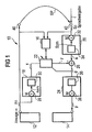
- a voice-controlled announcement system 10 is shown, which allows the user, a Speech input during an announcement.
- the announcement system 10 contains an announcement device 12 and a speech recognition device 14 as functionally essential components, a detector device 16 and an adaptive digital filter device.
- a first interpolator 18, a second interpolator 20, an adaptive digital filter 22, hereinafter also referred to as echo suppression filter with respect to its use, a decimator means 24 and an adder 26 are included.
- the first interpolator 18 includes a first sample rate increaser 28 and a first digital decorrelation filter 30 in series.
- the second interpolator 20 is constructed the same as the first interpolator 18 and thus includes a second sample rate increaser 32 and a second decorrelation filter 34 in series the second sample rate increaser 28, 32 and the first and second decorrelation filters 30, 34 may each be identical components.
- the decimator 24 consists of a digital equalization filter 36 and a subsequent sample rate reducer 38.
- An announcement of the announcement system is based on a digital announcement signal An, which is converted in a known manner by a DA converter (not shown) in an analog and then audible to the user signal.
- the announcement is supplied to the user via an output 40 of the announcement system 10.
- a digital speech input signal Sp is generated by AD conversion of an analog signal corresponding to the speech input, which is supplied to the announcement system 10 via an input 42.
- the announcement signal An and the speech input signal Sp are each a sequence of samples whose time interval is determined by a predetermined first sampling period.
- the first predetermined sampling period will hereinafter be referred to as a long sampling period and, correspondingly, the sampling rate of the announcement signal At and the voice input signal Sp referred to as a low sampling rate. Samples whose sampling times are given by the low sampling rate are also called "regular" in the following.
- the announcement signal An and the speech input signal Sp are supplied to the detector unit 16, which detects a simultaneous occurrence of announcement and voice input.
- the detector device 16 controls the echo suppression filter 22 and deactivates the later-described coefficient adaptation when announcement and voice input occur simultaneously. In this way, it is ensured that the adaptation of the echo suppression filter 22 takes place only when the announcement occurs alone.
- the announcement signal An and the speech input signal Sp are sampled at the predetermined low sampling rate.
- the first interpolation device 18 and the second interpolation device 20 have the function of generating from the announcement signal An or the voice input signal Sp a signal whose sampling rate is increased and whose sampled values are also decorrelated at least to a certain extent.
- the announcement signal An which is increased in its sampling rate by the first interpolation device 18 and is also decorrelated, is referred to below as the interpolated announcement signal x and its sampling rate as the high sampling rate.
- the speech input signal Sp which has passed through the second interpolation-part filter is referred to as interpolated speech input signal s.
- the first sample rate increaser 28 increases the sample rate or decreases the sample period of the announcement signal An by a predetermined factor M by inserting zero values between consecutive regular samples of the announcement signal An M-1. If the high sampling rate is set to F and thus the short sampling period is set to T, then the low sample rate is the value of the quotient of F and M and the long one Sample period given by the value of the product of M and T.
- a null signal-modified modified announcement signal, referred to below as nited is further processed in the first decorrelation filter 30.
- the transfer function H 'of the first decorrelation filter 30 is set as a function of the announcement so that the samples of the interpolated announcement signal x are at least partially decorrelated.
- the second interpolator 20 first generates from the speech input signal Sp a modified speech input signal, hereafter referred to as Spm, in which zero values are inserted between successive regular samples M-1, and from this the interpolated speech input signal s whose sampling rate is equal to that Factor M is increased and its samples are also decorrelated, as are the samples of the interpolated announcement signal x.
- Spm modified speech input signal
- the operation of the interpolators 18 and 20 will be described later with reference to FIGS FIGS. 2 to 9 explained.
- the echo suppression filter 22 has the task of freeing the voice input from an announcement echo, which is transmitted via an echo path EP from the output 40 to the input 42 of the announcement system 10 and enters there into the speech input signal Sp to be processed.
- the transmission characteristics of the echo path EP ie its transfer function, are reproduced by the echo cancellation filter 22 in a fast converging adaptation method.
- the echo cancellation filter 22 is supplied with the interpolated announcement signal x.
- the echo suppression filter 22 generates, as will be described, a compensation signal y at the predetermined high sampling rate.
- the compensation signal y is subtracted from the interpolated speech input signal s and a difference signal d is forwarded to the decimator device 24.
- the difference signal d is filtered by the equalizing filter 36 in a manner to be described later and supplied to the sampling rate lower 38. This reduces the sampling rate or lengthens the sampling period of the filtered difference signal d by the factor M by hiding the M-1 intermediate values between the regular samples.
- the sampling rate lower 38 finally forwards a useful signal p determined in this way to the speech recognition device 14.
- the useful signal p is sampled as the announcement signal An and the speech input signal Sp at the predetermined low sampling rate, i. the time interval between two consecutive samples equals the predetermined long sampling period.
- the speech recognition device 14 is provided with the useful signal p is a digital signal of the speech input freed from the announcement echo. In the speech recognition device 14, the relevant message content can be obtained from the speech input in a known manner.
- the first interpolator 18 and the second interpolator 20 may be adapted for use in the announcement system 10 Fig. 1 be constructed identically. For this reason will be in the following hand of the Figures 2 . 3 and 5 the construction and operation of the first interpolation device 18 is explained without again going into the second interpolation device 20. The same applies to the second interpolation device 20 as explained for the first interpolation device 18. In the Fig. 2 . 3 and 5 In addition, the reference numerals of the second interpolation device 20 are entered.
- the first interpolator 18 and the decimator 24 are shown.
- the first interpolator 18 is given by the first decorrelation filter 30 and the upstream sample rate increaser 28.
- the sampling rate increaser 28 increases the sampling rate of the announcement signal An by the predetermined factor M, By inserting M-1 zero values between two consecutive regular samples, thus generating the modified announcement signal
- the first decorrelation filter 30 includes M parallel-arranged decorrelation sub-filters IFT 0 to IFT M-1 to which the modified announcement signal Anm is supplied.
- Each of the decorrelation sub-filters IFT 0 to IFT M-1 may be subdivided into "memoryless" networks N 0 'to N' M-1 and delay units VE ' 0 to VE' M-1 .
- Memoryless networks are networks that can contain addition terms and multipliers, but no delay elements.
- the delay units VE ' 0 to VE' M-1 delay the modified announcement signal Anm by the long sampling period or a multiple of the long sampling period.
- the long sampling period is M times the short sampling period T.
- the outputs of the interpolation part filters IFT 0 to IFT M-1 are interconnected via a series arrangement in which M-1 delay elements VG 0 to VG M-2 and M adders AD 0 to AD M-1 are arranged in an alternating sequence.
- the outputs of the first M-2 decorrelation part filters IFT 0 to IFT M-2 are respectively connected to the corresponding addition element AD 0 to AD M-2 , while the output of the last decorrelation part filter IFT M-1 is connected to the delay element VG M-2 .
- the delay elements VG 0 to VG M-2 each ensure a signal delay corresponding to the short sampling period T.
- the first decorrelation filter 30 outputs the interpolated, ie the announcement signal x, which is increased in the sampling rate and at least partially decorrelated.
- the structure of the first decorrelation filter 30 just described is reflected in relation (1), which specifies how the transfer function H 'of the first decorrelation filter is composed of the transfer functions H' i of the decorrelation part filters IFT 0 to IFT M-1 .
- the modified sampling signal sampled at the high sampling rate Thus, Note may be processed in the first decorrelation filter 30 at substantially the low sampling rate because the decorrelation split filters IFT 0 to IFT M-1 operate at the low sampling rate.
- Each of the M-1 zero values inserted between two regular samples is converted into an intermediate value by one of the decorrelation part filters IFT 1 to IFT M-1 in accordance with the associated transfer function H ' i , such that the announcement signal modified by the insertion of the zero values Note the interpolated announcement signal x is generated.
- the degree of the desired decorrelation can be set as a function of the known announcement signal An via the transfer functions H ' i of the decorrelation part filters IFT 0 to IFT M-1 .
- the decimator device 24 is shown, which consists of the equalizing filter 36 and the subsequent sampling rate lower 38.
- the equalizing filter 36 in this embodiment contains only a single equalizer filter DFT 0 , which, like the decorrelation filter IFT 0 to IFT M-1 of the decorrelation filters 30 and 34, can be subdivided into a memoryless network N 0 "and a delay unit VE 0 ".
- the equalization filter IFT 0 is thus operated at the low sampling rate.
- the transfer function H 0 "of the equalizing filter 36 is linked to the transfer function H 0 'of the first decorrelation part filter IFT 0 of the decorrelation filters 30 and 34 via the relation (2).
- equation (2) for the regular samples of the difference signal d corresponding to the original samples of the announcement signal An and the speech input signal Sp, the signal variations caused by the transmission of the first decorrelation part filter IFT 0 of the decorrelation filters 30, 34 are compensated have been caused.
- the sampling rate lower 38 the M-1 intermediate values of the difference signal d occurring between two successive, regular sampling values are masked out, so that the useful signal p sampled at the low sampling rate is available at the output of the decimator device 24.
- the decimator 24 thus ensures that the samples of the useful signal p are not corrupted by the measures for sampling rate increase and decorrelation, ie that the voice input signal apart from the desired echo cancellation after interpolation and subsequent sampling rate reduction is as before.
- the first and second interpolation means 18 and 20 and the corresponding decimator means 24 are shown for an embodiment in which the first decorrelation part filter IFT 0 is a simple pass filter which supplies the modified announcement signal Anm or speech input signal Spm to the adder AD 0 without changes.
- the equalization filter DFT 0 is also a simple pass-through filter.
- the echo cancellation filter 22 generates the compensation signal y from the interpolated announcement signal x, which is supplied to it by the first interpolation device 18.
- the compensation signal y is based on N filter coefficients c 0 to c N-1 , which an adaptation unit 44 of the echo suppression filter 22 supplies.
- the adaptation unit 44 determines the N filter coefficients c 0 to c N-1 according to the LMS algorithm as a function of the difference signal d, which is formed in the adder 26 from the compensation signal y and the interpolated speech input signal s.
- the echo suppression filter 22 includes a delay chain having N-1 delays 46 which delay the interpolated announcement signal x by the long sampling period, ie, M times the short sampling period T.
- N multiplication elements 48 are arranged in parallel, which are each driven by the adaptation unit 44 with one of the N filter coefficients c 0 to c N-1 .
- the outputs of the multipliers 48 are linked together by a series arrangement of N-1 adders 50.
- the last addition element of the series arrangement which is connected to the multiplier element controlled via the filter coefficient c N-1 , feeds the compensation signal y to the addition element 26.
- the filter coefficients c 0 to c N-1 are determined in the adaptation unit 44 according to the LMS algorithm. For this purpose, in the time in which the announcement occurs alone, ie in which no double-talking conditions prevail, essentially the absolute value square of the difference signal d, which indicates the deviation of the compensation signal y from the interpolated speech input signal s, by adjusting the filter coefficients c 0 to c N-1 minimized. Since the delay elements 46 of the delay chain each cause a signal delay corresponding to the long sampling period, only such samples of the interpolated input signal x weighted by the filter coefficients c 0 to c N-1 , the time interval of which through the long sampling period, enter into a single sample of the compensation signal y given is.
- the first interpolator 18 and the decimator 24 are shown in which a sample rate increase by the factor M is made equal to two.
- the second interpolating means 20 is constituted as well as the first interpolating means 18, so that the same applies to the speech input signal Sp in the following with respect to the announcement signal An.
- the interpolation device 18 has the task of interpolating the announcement signal An between successive regular samples such that the in FIG. 6 illustrated coloring of the announcement is compensated as much as possible.
- the frequency response of the attenuation is plotted, as it is typically for human speech and thus for the announcement and the voice input.
- the in Fig. 6 The course shown shows the properties of a so-called low-pass dyeing.
- the decorrelation filter 18, 20 contains the two decorrelation part filters IFT 0 and IFT 1 .
- the first decorrelation part filter IFT 0 is formed as a simple pass filter whose transfer function H ' 0 is given by relation (3).
- the equalizing filter 36 includes only one equalizing filter DFT 0 which is also formed as a passage filter according to the relationship (3).
- the first decorrelation sub-filter IFT 1 includes a delay 52 which produces a k-fold signal delay of twice the short sampling period T. k is a whole, nonnegative number.
- the delay element 52 is followed by a delay element 54, which has a signal delay of the twice short sampling period generated, and a multiplier 56 whose output leads to the input of an adder 58. Between the delay elements 52 and 54, a multiplier 60 is provided branching, whose output is also guided on the summing element 58.
- Specified announcement signal is the multiplication factor of the multiplier 56 with 1 and the multiplication factor of the multiplier 60 with -1/2 set.
- the transfer function H ' 1 of in Fig. 5 shown Dekorrelationsteiltilters is suitable, the in Fig. 6 displayed coloring of the announcement or the voice input largely cancel. The efficiency with which this is possible depends on the constant k, as shown below.
- the multipliers 56, 60 are in the Figures 2 and 3 is designated as a memoryless network N 1 ', while the delay elements 52, 54 in these figures correspond to the delay unit VE 1 '.
- the announcement signal An or the speech input signal Sp is first supplied to the sampling rate increaser 28 or 32, which generates the modified, increased in the sampling rate announcement signal Anm or speech input signal Spm.
- the announcement signal An and the speech input signal Sp may be sampled at a sampling frequency of, for example, 8 kHz corresponding to the low sampling rate.
- the sampling rate increaser 28 or 32 thus increases the sampling frequency to 16 kHz.
- the modified announcement signal Anm or speech input signal Spm are now processed in a first processing branch by the first decorrelation part filter IFT 0 and in a second processing branch by the second decorrelation filter IFT 1 .
- the two output signals of the first decorrelation part filter IFT 0 and the second decorrelation part filter IFT 1 which are shifted in time by the delay element VG 0 by a short sampling period, added and output as interpolated announcement signal x and as interpolated speech input signal s.
- the difference signal d is forwarded unchanged by the compensation filter 36 to the sampling rate lower 38.
- the useful signal p thus generated which is sampled at the sampling frequency of 8 kHz like the announcement signal An and the voice input signal Sp, is supplied to the voice recognition unit 14.
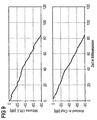
- FIGS. 7 to 9 two embodiments of the digital filter device according to the invention compared with an echo cancellation filter according to the prior art in terms of their convergence properties.
- the number N of filter coefficients c 0 to c N-1 is set at 64 for both the two embodiments of the invention and for the known echo cancellation filter.
- two variables are used in the following, namely the mean attenuation ERLE, "Error Return Loss Enhancement", of the echo path EP and the deviation of a coefficient vector summarizing the current filter coefficients from an optimal coefficient vector C opt, which gives the optimum filter coefficients.
- FIG. 7 illustrates the convergence behavior of a conventional echo suppression filter operating on the LMS algorithm.
- conventional echo cancellation there is no sampling rate increase and decorrelation of the announcement signal and the voice input signal.
- FIG. 8 the convergence behavior of the digital filter device after FIG. 5 shown in which the constant k of the delay element 52 is set to 0 for this embodiment.
- the time course of the mean damping ERLE of the echo path EP and the deviation from the optimum coefficient vector C opt reflect the significantly improved convergence behavior of the digital filter device according to the invention. If the constant k is increased, for example so that it is greater than or equal to half the number of filter coefficients, then the convergence behavior of the digital filter device can be significantly improved again.
- FIG. 9 is the convergence behavior of an embodiment of the digital filter device according to FIG.
Landscapes
- Filters That Use Time-Delay Elements (AREA)
- Cable Transmission Systems, Equalization Of Radio And Reduction Of Echo (AREA)
Claims (22)
- Procédé d'adaptation de coefficients dans un dispositif de filtrage numérique adaptatif,
dans lequel on augmente d'un facteur M le taux d'échantillonnage d'un signal d'entrée numérique (An) et d'un signal de référence numérique (Sp) pour passer d'une petite valeur prescrite à une grande valeur prescrite,
dans lequel on effectue au moins jusqu'à un certain degré la décorrélation des valeurs échantillonnées du signal d'entrée (Anm) échantillonné avec le grand taux d'échantillonnage et du signal de référence (Spm) échantillonné avec le grand taux d'échantillonnage,
dans lequel un filtre numérique adaptatif non récursif (22) produit à partir du signal d'entrée décorrélé (x) un signal de compensation (y) en se basant sur N coefficients de filtrage (c0 à cN-1) qui sont déterminés dans une unité d'adaptation (44) fonctionnant avec le grand taux d'échantillonnage en fonction d'un signal de différence (d) à partir du signal de référence décorrélé (s) et du signal de compensation (y) selon les moindres carrés d'erreur moyens,
et dans lequel on réduit le taux d'échantillonnage du signal de différence (d) du facteur M pour passer de la grande valeur prescrite à la petite valeur prescrite. - Procédé selon la revendication 1, caractérisé par le fait que l'on effectue de la même manière la décorrélation des valeurs échantillonnées du signal d'entrée (Anm) échantillonné avec le grand taux d'échantillonnage et du signal de référence (Spm) échantillonné avec le grand taux d'échantillonnage et que l'on effectue une compensation de la décorrélation au moins pour les valeurs échantillonnées du signal de différence (d) qui sont associées aux instants d'échantillonnage initiaux.
- Procédé selon la revendication 2, caractérisé par le fait que l'on envoie le signal d'entrée (An) à un premier dispositif d'interpolation (18) et le signal de référence (Sp) à un deuxième dispositif d'interpolation (20), dispositifs dans lesquels on effectue à chaque fois l'augmentation de taux d'échantillonnage au moyen d'un dispositif d'augmentation de taux d'échantillonnage (28, 32) et la décorrélation consécutive au moyen d'un filtre de décorrélation (30, 34).
- Procédé selon la revendication 3, caractérisé par le fait que l'on envoie le signal de différence (d) à un dispositif de décimation (24) dans lequel on effectue la compensation de la décorrélation au moyen d'un filtre d'équilibrage (36) et la diminution de taux d'échantillonnage consécutive au moyen d'un dispositif de diminution de taux d'échantillonnage (38).
- Procédé selon la revendication 3 ou 4, caractérisé par le fait que le dispositif d'augmentation de taux d'échantillonnage (28, 32) insère M - 1 valeurs intermédiaires entre des valeurs échantillonnées successives associées aux instants d'échantillonnage initiaux.
- Procédé selon la revendication 5, caractérisé par le fait que les valeurs intermédiaires sont nulles.
- Procédé selon la revendication 5 ou 6, caractérisé par le fait que le dispositif de diminution de taux d'échantillonnage (38) supprime M - 1 valeurs échantillonnées du signal de différence (d) qui se trouvent entre les instants d'échantillonnage initiaux.
- Procédé selon l'une des revendications 6 ou 7, caractérisé par le fait que le premier et le deuxième filtre de décorrélation (30, 34) contiennent chacun M filtres partiels de décorrélation (IFT0 à IFTM-1) qui peuvent être exploités avec le petit taux d'échantillonnage et dont les fonctions de transfert H'i donnent la fonction de transfert H' du premier et du deuxième filtre de décorrélation (30, 34) selon la relation suivante :

- Procédé selon la revendication 8, caractérisé par le fait que le filtre d'équilibrage (36) contient un premier filtre partiel d'équilibrage (DFT0) qui est exploité avec le petit taux d'échantillonnage et qui a une fonction de transfert H0'' pour laquelle la relation

- Procédé selon la revendication 9, caractérisé par le fait que le premier filtre partiel de décorrélation (IFT0) et le premier filtre partiel d'équilibrage (DFT0) sont des filtres transitoires dont les fonctions de transfert H0' et H0'' satisfont à la relation

- Procédé selon la revendication 9 ou 10, caractérisé par le fait que le filtre d'équilibrage (36) contient M - 1 autres filtres partiels d'équilibrage qui sont exploités avec le petit taux d'échantillonnage et dont les fonctions de transfert Hi'' donnent avec la fonction de transfert H0'' du premier filtre partiel d'équilibrage (DFT0) la fonction de transfert H'' du filtre d'équilibrage (36) selon la relation

- Procédé selon la revendication 10 ou 11, caractérisé par le fait que les M filtres partiels de décorrélation (IFT0 à IFTM-1) du premier et du deuxième filtre de décorrélation (30, 34) sont branchés à chaque fois en parallèle, qu'ils reçoivent le signal d'entrée (Anm) respectivement le signal de référence (Spm) échantillonné avec la période d'échantillonnage courte et que leurs sorties sont reliées entre elles par l'intermédiaire d'un montage série dans lequel M - 1 éléments de retardement (VG0 à VGM-2), provoquant chacun un retard de signal correspondant à la période d'échantillonnage courte, et M éléments additionneurs (AD0 à ADM-1) sont agencés en alternance.
- Procédé selon l'une des revendications précédentes, caractérisé par le fait que le filtre numérique adaptatif (22) est équipé d'une chaîne de retardement (46) de N - 1 éléments de retardement qui retardent le signal d'entrée décorrélé (x) à chaque fois d'une période d'échantillonnage longue correspondant au petit taux d'échantillonnage, d'un montage parallèle (48) dérivant de la chaîne de retardement et constitué de N éléments de multiplication (46) qui sont commandés par l'unité d'adaptation (44) à chaque fois avec l'un des N coefficients de filtrage (C0 à CN-1) et d'un montage série de N - 1 éléments d'addition (50) qui combine les sorties des éléments de multiplication entre elles et qui délivre le signal de compensation (y) à un autre élément d'addition (26), et on envoie le signal de référence décorrélé (s) à cet élément d'addition (26), l'élément d'addition détermine le signal de différence (d) à partir du signal de compensation (y) et du signal de référence (s) et il l'envoie à l'unité d'adaptation (44) du filtre numérique adaptatif (22).
- Procédé selon l'une des revendications précédentes, caractérisé par le fait qu'il est utilisé pour la compensation d'écho dans un système d'annonce (10) commandé vocalement.
- Dispositif de filtrage numérique adaptatif pour la mise en oeuvre du procédé selon l'une des revendications précédentes,
avec un premier dispositif d'interpolation (18) qui contient un premier dispositif d'augmentation de taux d'échantillonnage (28), qui augmente d'un facteur M le taux d'échantillonnage d'un signal d'entrée numérique (An) pour passer d'une petite valeur prescrite à une grande valeur prescrite, et un premier filtre de décorrélation (30) qui effectue au moins jusqu'à un certain degré la décorrélation des valeurs échantillonnées du signal d'entrée (Anm) échantillonné avec le grand taux d'échantillonnage,
avec un deuxième dispositif d'interpolation (20) qui contient un deuxième dispositif d'augmentation de taux d'échantillonnage (32), qui augmente du facteur M le taux d'échantillonnage d'un signal de référence numérique (Sp) pour passer de la petite valeur prescrite à la grande valeur prescrite, et un deuxième filtre de décorrélation (34), qui effectue au moins jusqu'à un certain degré la décorrélation des valeurs échantillonnées du signal de référence (Spm) échantillonné avec le grand taux d'échantillonnage,
avec un filtre numérique adaptatif non récursif (22) qui produit à partir du signal d'entrée décorrélé (x) un signal de compensation (y) en se basant sur N coefficients de filtrage (C0 à CN-1) qui sont déterminés dans une unité d'adaptation (44) fonctionnant avec le grand taux d'échantillonnage en fonction d'un signal de différence (d) à partir du signal de référence décorrélé (s) et du signal de compensation (y) selon les moindres carrés d'erreur moyens, et
avec un dispositif de décimation (24) qui réduit du facteur M le taux d'échantillonnage du signal de différence (d) pour passer de la grande valeur prescrite à la petite valeur prescrite. - Dispositif de filtrage numérique selon la revendication 15, caractérisé par le fait que le premier filtre de décorrélation (30) et le deuxième filtre de décorrélation (34) sont des composants à la fonction identique et que le dispositif de décimation (24) contient un filtre d'équilibrage (36) qui effectue une compensation de la décorrélation effectuée par le premier et le deuxième filtre de décorrélation (30, 34) au moins pour les valeurs échantillonnées du signal de différence (d) qui sont associées aux instants d'échantillonnage initiaux.
- Dispositif de filtrage numérique selon la revendication 16, caractérisé par le fait que le premier et le deuxième filtre de décorrélation (30, 34) contiennent chacun M filtres partiels (IFT0 à IFTM-1) qui peuvent être exploités avec le petit taux d'échantillonnage et dont les fonctions de transfert H'i donnent la fonction de transfert H' du premier et du deuxième filtre de décorrélation (30, 34) selon la relation suivante :

- Dispositif de filtrage numérique selon la revendication 17, caractérisé par le fait que le filtre d'équilibrage (36) contient un premier filtre partiel d'équilibrage (DFT0) qui est exploité avec le petit taux d'échantillonnage et qui a une fonction de transfert H0'' pour laquelle la relation

- Dispositif de filtrage numérique selon la revendication 18, caractérisé par le fait que le premier filtre partiel de décorrélation (IFT0) et le premier filtre partiel d'équilibrage (DFT0) sont des filtres transitoires dont les fonctions de transfert H0' et H0'' satisfont à la relation

- Dispositif de filtrage numérique selon la revendication 18 ou 19, caractérisé par le fait que le filtre d'équilibrage (36) contient M - 1 autres filtres partiels d'équilibrage qui sont exploités avec le petit taux d'échantillonnage et dont les fonctions de transfert Hi'' donnent avec la fonction de transfert H0'' du premier filtre partiel d'équilibrage (DFT0) la fonction de transfert H'' du filtre d'équilibrage (36) selon la relation

- Dispositif de filtrage numérique selon la revendication 19 ou 20, caractérisé par le fait que les M filtres partiels de décorrélation (IFT0 à IFTM-1) du premier et du deuxième filtre de décorrélation (30, 34) sont branchés à chaque fois en parallèle, qu'ils reçoivent le signal d'entrée (Anm) respectivement le signal de référence (Spm) échantillonné avec la période d'échantillonnage courte et que leurs sorties sont reliées entre elles par l'intermédiaire d'un montage série dans lequel M - 1 éléments de retardement (VG0 à VGM-2), provoquant chacun un retard de signal correspondant à la période d'échantillonnage courte, et M éléments additionneurs (AD0 à ADM-1) sont agencés en alternance.
- Dispositif de filtrage numérique selon l'une des revendications 15 à 21, caractérisé par le fait que le filtre numérique adaptatif (22) est équipé d'une chaîne de retardement (46) de N - 1 éléments de retardement qui retardent le signal d'entrée décorrélé (x) à chaque fois d'une période d'échantillonnage longue correspondant au petit taux d'échantillonnage, d'un montage parallèle (48) dérivant de la chaîne de retardement et constitué de N éléments de multiplication (46) qui sont commandés par l'unité d'adaptation (44) à chaque fois avec l'un des N coefficients de filtrage (C0 à CN-1) et d'un montage série de N - 1 éléments d'addition (50) qui combine les sorties des éléments de multiplication entre elles et qui délivre le signal de compensation (y) à un autre élément d'addition (26), et le signal de référence décorrélé (s) est envoyé à cet élément d'addition (26), l'élément d'addition détermine le signal de différence (d) à partir du signal de compensation (y) et du signal de référence (s) et il l'envoie à l'unité d'adaptation (44) du filtre numérique adaptatif (22).
Applications Claiming Priority (2)
| Application Number | Priority Date | Filing Date | Title |
|---|---|---|---|
| DE19740219 | 1997-09-12 | ||
| DE19740219 | 1997-09-12 |
Publications (3)
| Publication Number | Publication Date |
|---|---|
| EP0909029A2 EP0909029A2 (fr) | 1999-04-14 |
| EP0909029A3 EP0909029A3 (fr) | 2001-09-26 |
| EP0909029B1 true EP0909029B1 (fr) | 2008-04-16 |
Family
ID=7842202
Family Applications (1)
| Application Number | Title | Priority Date | Filing Date |
|---|---|---|---|
| EP19980117149 Expired - Lifetime EP0909029B1 (fr) | 1997-09-12 | 1998-09-10 | Méthode d'adaptation des coefficients de filtrage et dispositif de filtrage numérique adaptatif |
Country Status (2)
| Country | Link |
|---|---|
| EP (1) | EP0909029B1 (fr) |
| DE (1) | DE59814219D1 (fr) |
Families Citing this family (1)
| Publication number | Priority date | Publication date | Assignee | Title |
|---|---|---|---|---|
| CN101521497A (zh) * | 2009-04-14 | 2009-09-02 | 北京中星微电子有限公司 | 自适应上采样滤波器 |
Family Cites Families (2)
| Publication number | Priority date | Publication date | Assignee | Title |
|---|---|---|---|---|
| EP0554494B1 (fr) * | 1992-02-07 | 1995-06-14 | Siemens Aktiengesellschaft | Filtre numérique non récursif adaptatif |
| US5267266A (en) * | 1992-05-11 | 1993-11-30 | Bell Communications Research, Inc. | Fast converging adaptive equalizer using pilot adaptive filters |
-
1998
- 1998-09-10 EP EP19980117149 patent/EP0909029B1/fr not_active Expired - Lifetime
- 1998-09-10 DE DE59814219T patent/DE59814219D1/de not_active Expired - Lifetime
Also Published As
| Publication number | Publication date |
|---|---|
| DE59814219D1 (de) | 2008-05-29 |
| EP0909029A3 (fr) | 2001-09-26 |
| EP0909029A2 (fr) | 1999-04-14 |
Similar Documents
| Publication | Publication Date | Title |
|---|---|---|
| DE3044208C2 (de) | Interpolator zur Erhöhung der Wortgeschwindigkeit eines digitalen Signals | |
| DE2818204C2 (de) | Signalverarbeitungsanlage zur Ableitung eines störverringerten Ausgangssignals | |
| DE2207141C3 (de) | Schaltungsanordnung zur Unterdrückung unerwünschter Sprachsignale mittels eines vorhersagenden Filters | |
| DE3510660C2 (fr) | ||
| DE69023697T2 (de) | Koeffizientengenerator für digitale Filter. | |
| DE3118473C2 (de) | Verfahren zur Aufbereitung elektrischer Signale mit einer digitalen Filteranordnung | |
| EP0948237B1 (fr) | Procédé pour la suppression du bruit dans un signal de microphone | |
| DE69125349T2 (de) | Einstellungsverfahren für Einrichtungen zur Auslöschung Signalzerstreuungen in Nachrichtenübertragungssystemen | |
| DE69020488T2 (de) | Schallfeld-Steuerungssystem. | |
| DE69123579T2 (de) | Verfahren zur adaptiven Echokompensation und Einrichtung zur Durchführung des Verfahrens | |
| EP0758817A1 (fr) | Egaliseur pour signaux numériques | |
| EP0930801A2 (fr) | Circuit et procédé pour la suppression adaptative de la réaction acoustique | |
| DE19956088A1 (de) | Einseiten-Unterband-Filter | |
| EP0696848B1 (fr) | Procédé pour l'interpolation d'un signal numérique | |
| DE2707936C3 (de) | Einseitenband-FrequenzmultiplexÜbertragungssystem | |
| DE2839229C2 (de) | Frequenzweiche mit einem Transversalfilter | |
| DE3044582A1 (de) | Digitaler verstaerker, insbesondere zur verwendung in einer digitalen fernsprech-teilnehmerschaltung | |
| EP0639892B1 (fr) | Dispositif de filtrage numérique | |
| DE3702215C2 (fr) | ||
| EP0909029B1 (fr) | Méthode d'adaptation des coefficients de filtrage et dispositif de filtrage numérique adaptatif | |
| DE69306893T2 (de) | Verfahren zur Bestimmung der Transmittanz einer Filterschaltung zur Umwandlung der Impulsantwort eines Filters in eine Impulsantwort mit minimaler Phase und Filter zur Durchführung des Verfahrens | |
| EP0855806B1 (fr) | Suppresseur d'écho pour l'entrée par voix d'un système de dialogue | |
| DE69403328T2 (de) | Verfahren und vorrichtung zum filtern eines digitalen zeitsignals und anwendung für echokorrektur in einem übertragungskanal | |
| EP0402519B1 (fr) | Méthode et dispositif pour modifier la portée dynamique d'un circuit adaptatif récursif pour le traitement de signaux en temps discret | |
| DE69931849T2 (de) | Zeitdiskretes filter |
Legal Events
| Date | Code | Title | Description |
|---|---|---|---|
| PUAI | Public reference made under article 153(3) epc to a published international application that has entered the european phase |
Free format text: ORIGINAL CODE: 0009012 |
|
| AK | Designated contracting states |
Kind code of ref document: A2 Designated state(s): AT BE CH CY DE DK ES FI FR GB GR IE IT LI LU MC NL PT SE Kind code of ref document: A2 Designated state(s): DE FR GB IT |
|
| AX | Request for extension of the european patent |
Free format text: AL;LT;LV;MK;RO;SI |
|
| PUAL | Search report despatched |
Free format text: ORIGINAL CODE: 0009013 |
|
| AK | Designated contracting states |
Kind code of ref document: A3 Designated state(s): AT BE CH CY DE DK ES FI FR GB GR IE IT LI LU MC NL PT SE |
|
| AX | Request for extension of the european patent |
Free format text: AL;LT;LV;MK;RO;SI |
|
| 17P | Request for examination filed |
Effective date: 20010823 |
|
| AKX | Designation fees paid |
Free format text: DE FR GB IT |
|
| GRAP | Despatch of communication of intention to grant a patent |
Free format text: ORIGINAL CODE: EPIDOSNIGR1 |
|
| GRAS | Grant fee paid |
Free format text: ORIGINAL CODE: EPIDOSNIGR3 |
|
| GRAA | (expected) grant |
Free format text: ORIGINAL CODE: 0009210 |
|
| AK | Designated contracting states |
Kind code of ref document: B1 Designated state(s): DE FR GB IT |
|
| REF | Corresponds to: |
Ref document number: 59814219 Country of ref document: DE Date of ref document: 20080529 Kind code of ref document: P |
|
| ET | Fr: translation filed | ||
| PLBE | No opposition filed within time limit |
Free format text: ORIGINAL CODE: 0009261 |
|
| STAA | Information on the status of an ep patent application or granted ep patent |
Free format text: STATUS: NO OPPOSITION FILED WITHIN TIME LIMIT |
|
| 26N | No opposition filed |
Effective date: 20090119 |
|
| PGFP | Annual fee paid to national office [announced via postgrant information from national office to epo] |
Ref country code: DE Payment date: 20101124 Year of fee payment: 13 |
|
| PGFP | Annual fee paid to national office [announced via postgrant information from national office to epo] |
Ref country code: FR Payment date: 20111005 Year of fee payment: 14 Ref country code: GB Payment date: 20110923 Year of fee payment: 14 |
|
| PGFP | Annual fee paid to national office [announced via postgrant information from national office to epo] |
Ref country code: IT Payment date: 20110927 Year of fee payment: 14 |
|
| REG | Reference to a national code |
Ref country code: GB Ref legal event code: 732E Free format text: REGISTERED BETWEEN 20121025 AND 20121031 |
|
| REG | Reference to a national code |
Ref country code: FR Ref legal event code: TP Owner name: SIEMENS ENTERPRISE COMMUNICATIONS GMBH & CO. K, DE Effective date: 20130108 |
|
| REG | Reference to a national code |
Ref country code: DE Ref legal event code: R082 Ref document number: 59814219 Country of ref document: DE Representative=s name: FRITZSCHE PATENT, DE |
|
| REG | Reference to a national code |
Ref country code: DE Ref legal event code: R082 Ref document number: 59814219 Country of ref document: DE Representative=s name: FRITZSCHE PATENT, DE Effective date: 20130313 Ref country code: DE Ref legal event code: R081 Ref document number: 59814219 Country of ref document: DE Owner name: SIEMENS ENTERPRISE COMMUNICATIONS GMBH & CO. K, DE Free format text: FORMER OWNER: SIEMENS AKTIENGESELLSCHAFT, 80333 MUENCHEN, DE Effective date: 20130313 |
|
| GBPC | Gb: european patent ceased through non-payment of renewal fee |
Effective date: 20120910 |
|
| REG | Reference to a national code |
Ref country code: FR Ref legal event code: ST Effective date: 20130531 |
|
| PG25 | Lapsed in a contracting state [announced via postgrant information from national office to epo] |
Ref country code: DE Free format text: LAPSE BECAUSE OF NON-PAYMENT OF DUE FEES Effective date: 20130403 Ref country code: GB Free format text: LAPSE BECAUSE OF NON-PAYMENT OF DUE FEES Effective date: 20120910 |
|
| REG | Reference to a national code |
Ref country code: DE Ref legal event code: R119 Ref document number: 59814219 Country of ref document: DE Effective date: 20130403 |
|
| PG25 | Lapsed in a contracting state [announced via postgrant information from national office to epo] |
Ref country code: FR Free format text: LAPSE BECAUSE OF NON-PAYMENT OF DUE FEES Effective date: 20121001 Ref country code: IT Free format text: LAPSE BECAUSE OF NON-PAYMENT OF DUE FEES Effective date: 20120910 |
|
| REG | Reference to a national code |
Ref country code: FR Ref legal event code: CD Owner name: UNIFY GMBH & CO.KG, DE Effective date: 20140429 |