EP0909064B1 - Système de communication pour la commande d'acheminement entre un réseau commuté en mode circuit et l'Internet - Google Patents
Système de communication pour la commande d'acheminement entre un réseau commuté en mode circuit et l'Internet Download PDFInfo
- Publication number
- EP0909064B1 EP0909064B1 EP98410091A EP98410091A EP0909064B1 EP 0909064 B1 EP0909064 B1 EP 0909064B1 EP 98410091 A EP98410091 A EP 98410091A EP 98410091 A EP98410091 A EP 98410091A EP 0909064 B1 EP0909064 B1 EP 0909064B1
- Authority
- EP
- European Patent Office
- Prior art keywords
- telephone
- signal
- gatekeeper
- telephone number
- address
- Prior art date
- Legal status (The legal status is an assumption and is not a legal conclusion. Google has not performed a legal analysis and makes no representation as to the accuracy of the status listed.)
- Expired - Lifetime
Links
Images


Classifications
-
- H—ELECTRICITY
- H04—ELECTRIC COMMUNICATION TECHNIQUE
- H04Q—SELECTING
- H04Q3/00—Selecting arrangements
- H04Q3/0016—Arrangements providing connection between exchanges
- H04Q3/0029—Provisions for intelligent networking
- H04Q3/0045—Provisions for intelligent networking involving hybrid, i.e. a mixture of public and private, or multi-vendor systems
-
- H—ELECTRICITY
- H04—ELECTRIC COMMUNICATION TECHNIQUE
- H04M—TELEPHONIC COMMUNICATION
- H04M3/00—Automatic or semi-automatic exchanges
- H04M3/42—Systems providing special services or facilities to subscribers
- H04M3/54—Arrangements for diverting calls for one subscriber to another predetermined subscriber
- H04M3/545—Arrangements for diverting calls for one subscriber to another predetermined subscriber with loop avoiding arrangements
-
- H—ELECTRICITY
- H04—ELECTRIC COMMUNICATION TECHNIQUE
- H04M—TELEPHONIC COMMUNICATION
- H04M7/00—Arrangements for interconnection between switching centres
- H04M7/12—Arrangements for interconnection between switching centres for working between exchanges having different types of switching equipment, e.g. power-driven and step by step or decimal and non-decimal
- H04M7/1205—Arrangements for interconnection between switching centres for working between exchanges having different types of switching equipment, e.g. power-driven and step by step or decimal and non-decimal where the types of switching equipement comprises PSTN/ISDN equipment and switching equipment of networks other than PSTN/ISDN, e.g. Internet Protocol networks
- H04M7/1225—Details of core network interconnection arrangements
-
- H—ELECTRICITY
- H04—ELECTRIC COMMUNICATION TECHNIQUE
- H04M—TELEPHONIC COMMUNICATION
- H04M2207/00—Type of exchange or network, i.e. telephonic medium, in which the telephonic communication takes place
- H04M2207/12—Type of exchange or network, i.e. telephonic medium, in which the telephonic communication takes place intelligent networks
-
- H—ELECTRICITY
- H04—ELECTRIC COMMUNICATION TECHNIQUE
- H04M—TELEPHONIC COMMUNICATION
- H04M7/00—Arrangements for interconnection between switching centres
- H04M7/12—Arrangements for interconnection between switching centres for working between exchanges having different types of switching equipment, e.g. power-driven and step by step or decimal and non-decimal
- H04M7/1205—Arrangements for interconnection between switching centres for working between exchanges having different types of switching equipment, e.g. power-driven and step by step or decimal and non-decimal where the types of switching equipement comprises PSTN/ISDN equipment and switching equipment of networks other than PSTN/ISDN, e.g. Internet Protocol networks
- H04M7/125—Details of gateway equipment
-
- H—ELECTRICITY
- H04—ELECTRIC COMMUNICATION TECHNIQUE
- H04M—TELEPHONIC COMMUNICATION
- H04M7/00—Arrangements for interconnection between switching centres
- H04M7/12—Arrangements for interconnection between switching centres for working between exchanges having different types of switching equipment, e.g. power-driven and step by step or decimal and non-decimal
- H04M7/1205—Arrangements for interconnection between switching centres for working between exchanges having different types of switching equipment, e.g. power-driven and step by step or decimal and non-decimal where the types of switching equipement comprises PSTN/ISDN equipment and switching equipment of networks other than PSTN/ISDN, e.g. Internet Protocol networks
- H04M7/128—Details of addressing, directories or routing tables
Definitions
- the present invention relates to a communication system performing routing control between circuit switched network and interconnection network comprising protocol for network communication.
- ITU-T Recommendation H.323 may be utilized as a protocol for call control in an interconnection network (hereinafter called as internet) having network communication protocol like LAN, WAN or the Internet based on the IP networking technique.
- H.323 includes Q.931 protocol which is used as a call control signaling for establishing and releasing calls among terminal equipment and gateways in the internet, where the gateway is an equipment which interconnects between a call in the circuit switched network such as telephone networks, integrated services digital networks and mobile communication networks and a call in the internet.
- the network architecture in the H.323 includes a gatekeeper which performs functions of address translation, access control, bandwidth management, etc. The gatekeeper may have additional functions relating to the call control such as a conference call control.
- a public switched telephone network is constructed as Intelligent Network (IN) in order to provide enhanced and diversified network service.
- the IN is a network connection architecture recommended in Q.1200 series of ITU-T. Difference between conventional network and the IN are two points of independence and integration of the service control function from the switching equipment.
- An aim of the conventional telephone switching system is to efficiently provide one to one communication services.
- complex addition and modification on the function are required. Therefore, advancing of services is somewhat limited.
- the IN solves this problem by constructing a layered structure such that the switching equipment executes a basic call connection function and a dedicated information processing equipment executes a function for providing complex services.
- a service control function needed for realization, maintenance and operation of the network services is integrated and controlling, monitoring and managing of the call control part are performed so as to meet an introduction of advanced network services. Additional services such as freephone service, abbreviated dialing service, virtual private network service and transfer service are realized with the IN technique.
- FIG. 1 A part of structure of IN can be seen in Fig. 1.
- a call control part 11 for performing only basic connection of a circuit such as a digital switching system
- a service control part 12 for directing the service to the call control part 11
- a service control information database 13 for storing service control information
- these additional services are realized by adding a service control function to a server equipment connected to the PBX.
- the internet provides gatekeeper.
- the information terminal C1 inquires to the gatekeeper and thus the gatekeeper responds by retrieving a gateway address AG1 for the called telephone number NT1. Therefore, the gatekeeper has an address table to take the correspondence between the telephone number and the address of the gateway used to connect to the telephone number.
- the routing control can be thus performed by selecting the address of nearest gateway depending upon the called telephone number informed from the calling information terminal.
- an inconvenience may come out in case of usage of the call transfer service.
- the service control part of the telephone switching system which detects that the telephone terminal T1 is called, needs to execute a procedure for terminating the call to the information terminal C2 by transferring again the call into the internet through the gateway.
- Such wasteful procedure between the networks will produce further consumption of the communication resources.
- This problem is caused by that the one communication network has only information for call transfer to the other communication network. The similar problem will occur in case that a mobile terminal equipment to be called in the mobile communication network is roaming when a call is arrived to the mobile communication network from the internet.
- WO 97 16007 discloses a gateway between networks using different protocols.
- WO 96 38018 discloses a method for setting up a speech connection in different network.
- a routing control communication system includes a circuit switched network provided with a service control information database having a telephone numbers table, an interconnection network provided with a network communication protocol and an information terminal, and a network interworking equipment, such as a gateway, provided with one terminal connected with the circuit switched network and the other terminal connected with the interconnection network.
- the information database is connected with the interconnection network, and the information terminal of the interconnection network is constituted so as to obtain a transferred terminal number corresponding to a called telephone number from the service control information database.
- the information terminal can inquire directly whether there is a transferred terminal number corresponding to a called telephone number in the service control information database of IN facility.
- the transferred terminal number corresponds to a telephone number (E.164) of the circuit switched network
- the transferred terminal number is an address of the interconnection network, it is possible to send a call directly to the address.
- the information terminal of the interconnection network for obtaining the terminal number to be transferred includes a memory unit for storing relationship information between the received called telephone number and the transferred terminal number. Consequently, an information terminal is not necessary to inquire again to the same called telephone number. Since, however, the obtained information may become incorrect and thus the use of the information as a permanent one may cause misaddressing, then it is desired to use a cache memory for temporary storage of the information.
- the transferred terminal number identifies a telephone number of a circuit switched network, or an address of the interconnection network. It is possible to call the address of corresponding gateway if it is the telephone number of the circuit switched network. It is possible to directly call the address if it is the address of the interconnection network.
- the information terminal of the interconnection network for obtaining the transferred terminal number is a gatekeeper having an address table of the interconnection network
- the service control information database is constituted so as to obtain from the gatekeeper a telephone number of a transferred gateway which corresponds to a called address.
- the routing control communication system which efficiently uses communication resources can be realized by communicating with each other for the service control information database having the telephone number table and the gatekeeper having the address table.
- a plurality of gateway telephone numbers to be transferred are obtained from the gatekeeper, simultaneously.
- the telephone network can select automatically with high priority gateway from the view point of quality service.
- an interworking equipment is connected to the service control information database, and that the interworking equipment performs mutual signal exchange for enquiry / response signals.
- the interworking equipment performs mutual signal exchange for enquiry / response signals.
- the interworking equipment includes a memory unit for storing information relating to mutual signal exchange of enquiry / response signals.
- the circuit switched network includes an IN facility.
- the service control information database can be separated from the switching equipment which is a call control part, the invention can be easily realized.
- the network control equipment is a gateway.
- Fig. 1 shows a functional diagram of routing control communication system between a telephone network and an internet as a preferred embodiment according to the present invention.
- a telephone terminal T1 provided with telephone number NT1 and a telephone terminal T2 provided with telephone number NT2 are depicted.
- a service control information database 131 and an interworking equipment 132 are both shown as in a service database equipment 13.
- a gatekeeper 17 provided with address AK an information terminal C1 provided with an address AC1 and an information terminal C2 provided with an address AC2 are shown in each other.
- a gateway 1 having a telephone number NG1 and an address AG1 and a gateway 2 having a telephone number NG2 and an address AG2 are shown.
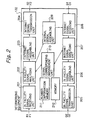
- FIG. 2 shows functional diagram of the interworking equipment in the embodiment of Fig. 1
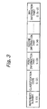
- Fig. 3 shows an execution format of signal information to be sent / received through the interworking equipment in the embodiment of Fig. 1. Operations of the interworking equipment in Fig. 2 is hereinafter illustrated by using signal information of Fig. 3.
- the signal format of communicating with the interworking equipment is as follows;
- the interworking equipment includes a conversion function for back / force depending on inquire / response of telephone number and address. In this embodiment, this is installed within the IN facility. In other embodiments, the interworking equipment may be implemented separately from the IN facility with having a communication link between the equipment and the IN facility.
- the interworking equipment between the IN facility and the gatekeeper performs as following two cases;
- the equipment of internet side may be only the information terminal or the gatekeeper. Whichever performance is similar, then the description will be done with gatekeeper.
- Fig. 2 shows that, in the interworking equipment 132, the inquiring signal F1 provided with a transferred address is inputted from the IN facility and its conversion signal F2 is outputted for the gatekeeper. Also, the response signal G1 for the inquiring signal F1 is inputted from the IN facility and its conversion signal G2 is outputted for the IN facility.
- the service control part 12 of the IN facility which receives an inquiry relating to called telephone number X1 from the switching equipment generating a call obtains the transferred address Y1 of the called telephone number from the record in the service control information database 131.
- the service control part 12 composes the inquiring signal F1 for the gateway telephone number including address Y1, and sends the signal F1 to the interworking equipment 132.
- the inquiring signal F1 is received with the IN facility signal receiving unit 201 in the interworking equipment 132.
- the signal receiving unit 201 sends the inquiring signal F1 for the IN facility signal analyzing unit 202.
- the signal analyzing unit 202 analyzes the contents of the signal F1, and then discriminate its inquiring contents.
- the signal analyzing unit 202 moreover, composes the inquiring signal F2 of the gateway telephone number to the address Y1 for the gatekeeper of the internet indicating the internet signal assembling unit 203.
- the assembling unit 203 composes of the following inquiring signal F2;
- the gatekeeper 17 identifies that it should be inquiry about the gateway telephone number from the discriminating code of F2(2) when receiving the inquiring signal F2.
- the gatekeeper 17 has the correspondence table between the address and the gateway telephone number.
- the correspondence table is administrated within the internet, and the correspondence between the address and the gateway telephone number is used to modify properly depending upon the internal status of the internet, network topology and circuit bandwidth.
- the gatekeeper 17 then retrieves the contents of the correspondence table with the inquiry signal F2 and obtains the gateway telephone number Z1(m) corresponding with the address Y1.
- the gateway telephone number Z1(1, 2, . . . , M) includes plural gateway telephone numbers and hereupon, Z1(m) shows mth candidate for telephone number.
- the gatekeeper sends obtained gateway telephone number group Z1(1, 2, . . , M) to the interworking equipment 132.
- the response signal G1 from the gatekeeper 17 is received at the internet signal receiving unit 208 of the interworking equipment 132, and is transmitted to the internet signal analyzing unit 207.
- the signal analyzing unit 207 analyzes the contents of the received response signal G1, obtains reference number with inquiring for the signal correspondent administration unit 210, compares the obtained reference number with reference number included in the response signal G1, and confirms to be corresponding response to the inquiring signal F1. After that, the unit 207 discriminates to be the response for inquiry from the identifying code of G1(2). Then, in order to notify to the IN facility of inquiring source the contents, obtained gateway telephone number group Z1(1, 2, . . . , M), responding to the inquiring signal F1, it directs to the IN facility signal transmission unit 205 so as to compose a signal G2 and to transmit the composed signal G2.
- the signal transmission unit 205 sends the response signal G2 including the gateway telephone number group Z1(1, 2, , . . . , M) to the IN facility.
- the IN facility receives the response signal G2 and it obtains the gateway telephone number group Z1(1, 2, . . , M) for the address Y1 from its contents. In a consequence, the IN facility recognizes the gateway group to be connected, and informs to the generating source switching equipment for the gateway telephone number group Z1(1, 2, . . . , M) or the one of the gateway telephone number Z1(m) and address Y1.
- the generating source switching equipment at receiving this information, selects the one from received gateway telephone number group Z1(1, 2, . . . , M), and together with proceeding the arrange for connecting to the gateway of its number, the address Y1 of called terminal is informed to the gateway with indicating on the information element of the call connection control signal.
- the gateway which has received the call connection signal for a call, reads out the address Y1 of called terminal indicating on the information element of the call connection control signal, and connects the call to the called terminal of the internet.
- the call connection based on the called number X1 of the call completes at all.
- the gateway corresponding first number Z1(1) of the gateway telephone number group Z1(1, 2, . . . , M) is nearest gateway for called terminal on the transmission delay within the internet.
- the calling source switching equipment would be set such as to select its gateway in priority, it should be enable to select in automatically a connection route with the smallest signal delay in the internet.
- the IN facility signal assembling unit 206, the IN facility signal transmission unit 205 and the IN facility signal receiving unit 201 should possess functions of transmitting / receiving of an information depending on the communication procedure to communicate with the database equipment in the private communication network.
- the interworking equipment 132 inquires the transferred telephone number T2 to the number conversion database equipment of the home mobile communication network so that the called terminal inquires for the transferred telephone number T3 to the roaming mobile communication network.
- the interworking equipment 132 holds the telephone number classified information table, as shown in Table 1, in the number information memory 211.
- the IN facility signal analyzing unit 202 when obtaining the transferred telephone number T2, refers the telephone number classified information table in the number information memory, and checks that [the called number T1 is equal to the number using freephone service] and [the transferred telephone number T2 is equal to the terminal logic telephone number registered in mobile communication network].
- the IN facility signal analyzing unit 202 when it is judged that the above-mentioned conditions are satisfied, directs to the internal signal assembling unit 209 to execute process of the inquiry again.
- the directed signal assembling unit 209 composes new inquiry signal Q3 as follows;
- the interworking equipment according to the present invention is realized in the gatekeeper, it is possible to use the bus in the gatekeeper equipment.
- the present invention it is possible to efficiently use communication resources at setting up the route of the call connection between the interconnection network having network communication protocol and circuit switched network. For instance, it is possible to inquire to the service control information database of the IN facility, whether there is a transferred terminal number for called telephone number or not. In case that the transferred terminal number is the telephone number, it is possible to transfer for telephone number of optimum gateway. If transferred terminal number is an address of a interconnection network, it is possible to call directly for prescribed address. In short, it is not to pay for useless communication cost.
- the gatekeeper having address table is connected with the internet, it is possible to embody the routing control of communication systems using communication resources efficiently by mutual communicating with service control information database provided with telephone number table. It is not necessary to administrate for network information of each other, by performing of inquiry / response for table information with between both, and then it is not needs for complexity of communication systems. Also, for a role of protocol conversion on the service control information database and the gatekeeper, it is possible to use for existing IN facility and the gatekeeper. Besides, as the transferred gateway in communications, it is possible to select the available gateway for the route of quality agreed with needs of communication user for called terminal and communication route.
- the network routing control communication systems according to the present invention with special structure mentioned above can offer special effects for communication enterpriser, service provider and user.
Landscapes
- Engineering & Computer Science (AREA)
- Computer Networks & Wireless Communication (AREA)
- Signal Processing (AREA)
- Data Exchanges In Wide-Area Networks (AREA)
- Telephonic Communication Services (AREA)
- Small-Scale Networks (AREA)
Claims (10)
- Système de communication à commande de routage comprenant un réseau commuté en mode circuit (11) qui comporte une pluralité de terminaux téléphoniques (T1, T2) et une base de données d'informations de contrôle de service (131), un réseau en protocole Internet (15) incluant une pluralité de terminaux de données (C1, C2) et un garde-barrière (17) muni d'une table d'adresse mémorisant les adresses des terminaux de données respectifs, et une pluralité de passerelles (14) connectées entre le réseau commuté en mode circuit (11) et le réseau en protocole Internet (15), la table d'adresse dans le garde-barrière (17) mémorisant en outre les adresses des passerelles respectives et la correspondance entre les numéros de téléphone des terminaux téléphoniques et les adresses des passerelles à utiliser pour connecter les terminaux de données aux terminaux téléphoniques ;
caractérisé en ce que la base de données d'informations de contrôle de service (131) est munie d'une table de numéros de téléphone mémorisant les numéros de téléphone des terminaux téléphoniques respectifs et la correspondance entre les numéros de téléphone des terminaux téléphoniques et leurs numéros de téléphone ou adresses de transfert d'appel indiquant d'autres numéros de téléphone des terminaux téléphoniques respectifs ou adresses des terminaux de données respectifs, auxquels des appels incidents doivent être transférés, le système comprenant en outre un équipement d'interopérabilité (132) connecté entre la base de données d'informations de contrôle de service (131) dans le réseau commuté en mode circuit (11) et le garde-barrière (17) dans le réseau en protocole Internet (15), le garde-barrière (17) étant adapté à envoyer à l'équipement d'interopérabilité (132) un premier signal d'interrogation (Q1) représentatif d'un numéro de téléphone appelé à partir d'un terminal de données parmi la pluralité de terminaux de données (C1, C2), l'équipement d'interopérabilité (132) étant adapté à déterminer un second signal d'interrogation (Q2) représentatif du numéro de téléphone en provenance du premier signal d'interrogation (Q1) et à envoyer le second signal d'interrogation (Q2) à la base de données d'informations de contrôle de service (131), la base de données d'informations de contrôle de service (131) étant adaptée à envoyer à l'équipement d'interopérabilité (132) un premier signal de réponse (R1) représentatif d'un numéro de téléphone ou d'une adresse de transfert d'appel correspondant au numéro de téléphone en provenance de la table de numéros de téléphone, l'équipement d'interopérabilité (132) étant adapté à déterminer un second signal de réponse (R2) représentatif du numéro de téléphone ou de l'adresse de transfert d'appel à partir du premier signal de réponse (R1) et à envoyer le second signal de réponse (R2) au garde-barrière (17). - Système selon la revendication 1, dans lequel le numéro de téléphone ou l'adresse de transfert d'appel obtenu à partir du garde-barrière (17) est un numéro de téléphone d'un terminal téléphonique dans le réseau commuté en mode circuit (11).
- Système selon la revendication 1, dans lequel le numéro de téléphone ou l'adresse de transfert d'appel obtenue par le garde-barrière (17) est une adresse d'un terminal de données dans le réseau en protocole Internet (15).
- Système selon la revendication 1, dans lequel l'équipement d'interopérabilité (132) réalise un échange de signaux pour les signaux d'interrogation/réponse.
- Système selon la revendication 4, dans lequel l'équipement d'interopérabilité (132) comprend un moyen de mémoire (212) pour mémoriser les informations relatives à l'échange de signaux pour les signaux d'interrogation/réponse.
- Système selon la revendication 1, dans lequel le réseau commuté en mode circuit (11) inclut un réseau intelligent.
- Système de communication à commande de routage comprenant un réseau commuté en mode circuit (11) qui comporte une pluralité de terminaux téléphoniques (T1, T2) et une base de données d'informations de contrôle de service (131), un réseau en protocole Internet (15) incluant une pluralité de terminaux de données (C1, C2) et un garde-barrière (17) muni d'une table d'adresse mémorisant les adresses des terminaux de données respectifs, et une pluralité de passerelles (14) connectées entre le réseau commuté en mode circuit (11) et le réseau en protocole Internet (15), la table d'adresse dans le garde-barrière (17) mémorisant en outre les numéros d'identification des passerelles respectives et la correspondance entre les adresses des terminaux de données et les numéros d'identification des passerelles à utiliser pour connecter les terminaux téléphoniques aux terminaux de données ;
caractérisé en ce que la base de données d'informations de contrôle de service (131) est munie d'une table de numéros de téléphone mémorisant les numéros de téléphone des terminaux téléphoniques respectifs et la correspondance entre les numéros de téléphone des terminaux téléphoniques et leurs numéros de téléphone ou adresses de transfert d'appel indiquant d'autres numéros de téléphone des terminaux téléphoniques respectifs ou adresses des terminaux de données respectifs, auxquels des appels incidents doivent être transférés, le système comprenant en outre un équipement d'interopérabilité (132) connecté entre la base de données d'informations de contrôle de service (131) dans le réseau commuté en mode circuit (11) et le garde-barrière (17) dans le réseau en protocole Internet (15), la base de données d'informations de contrôle de service (131) étant adaptée à envoyer à l'équipement d'interopérabilité (132) un premier signal d'interrogation (F1) représentatif d'une adresse d'un terminal de données auquel un terminal téléphonique doit être connecté, l'équipement d'interopérabilité (132) étant adapté à déterminer un second signal d'interrogation (F2) représentatif de l'adresse en provenance du premier signal d'interrogation (F1) et à envoyer le second signal d'interrogation (F2) au garde-barrière (17), le garde-barrière (17) étant adapté à envoyer à l'équipement d'interopérabilité (132) un premier signal de réponse (G1) représentatif d'au moins un numéro d'identification d'au moins une passerelle à utiliser pour connecter le terminal téléphonique au terminal de données à partir de la table d'adresses, l'équipement d'interopérabilité (132) étant adapté à déterminer un second signal de réponse (G2) représentatif dudit au moins un numéro d'identification à partir du premier signal de réponse (G1) et à envoyer le second signal de réponse (G2) à la base de données d'informations de contrôle de service (131). - Système selon la revendication 7, dans lequel l'équipement d'interopérabilité (132) réalise un échange de signaux pour les signaux d'interrogation/réponse.
- Système selon la revendication 8, dans lequel l'équipement d'interopérabilité (132) comprend un moyen de mémoire (212) pour mémoriser les informations relatives à l'échange de signaux pour les signaux d'interrogation/réponse.
- Système selon la revendication 7, dans lequel le réseau commuté en mode circuit (11) inclut un réseau intelligent.
Applications Claiming Priority (3)
| Application Number | Priority Date | Filing Date | Title |
|---|---|---|---|
| JP22896597 | 1997-08-12 | ||
| JP22896597A JP3346234B2 (ja) | 1997-08-12 | 1997-08-12 | 回線交換網とインターネット網との網間経路制御通信システム |
| JP228965/97 | 1997-08-12 |
Publications (3)
| Publication Number | Publication Date |
|---|---|
| EP0909064A2 EP0909064A2 (fr) | 1999-04-14 |
| EP0909064A3 EP0909064A3 (fr) | 1999-09-01 |
| EP0909064B1 true EP0909064B1 (fr) | 2005-10-19 |
Family
ID=16884648
Family Applications (1)
| Application Number | Title | Priority Date | Filing Date |
|---|---|---|---|
| EP98410091A Expired - Lifetime EP0909064B1 (fr) | 1997-08-12 | 1998-08-10 | Système de communication pour la commande d'acheminement entre un réseau commuté en mode circuit et l'Internet |
Country Status (4)
| Country | Link |
|---|---|
| US (1) | US6456617B1 (fr) |
| EP (1) | EP0909064B1 (fr) |
| JP (1) | JP3346234B2 (fr) |
| DE (1) | DE69831909T2 (fr) |
Families Citing this family (47)
| Publication number | Priority date | Publication date | Assignee | Title |
|---|---|---|---|---|
| GB9603582D0 (en) | 1996-02-20 | 1996-04-17 | Hewlett Packard Co | Method of accessing service resource items that are for use in a telecommunications system |
| US6154445A (en) | 1996-04-18 | 2000-11-28 | Bell Atlantic Network Services, Inc. | Telephony communication via varied redundant networks |
| US6069890A (en) | 1996-06-26 | 2000-05-30 | Bell Atlantic Network Services, Inc. | Internet telephone service |
| US6078582A (en) | 1996-12-18 | 2000-06-20 | Bell Atlantic Network Services, Inc. | Internet long distance telephone service |
| US6137869A (en) | 1997-09-16 | 2000-10-24 | Bell Atlantic Network Services, Inc. | Network session management |
| US6574216B1 (en) | 1997-03-11 | 2003-06-03 | Verizon Services Corp. | Packet data network voice call quality monitoring |
| US6292479B1 (en) | 1997-03-19 | 2001-09-18 | Bell Atlantic Network Services, Inc. | Transport of caller identification information through diverse communication networks |
| US6870827B1 (en) | 1997-03-19 | 2005-03-22 | Verizon Services Corp. | Voice call alternative routing through PSTN and internet networks |
| KR100252120B1 (ko) | 1997-12-29 | 2000-04-15 | 윤종용 | Ip가 지원되는 케이블망에서의 인터넷 텔리포니 서비스 장치및 방법 |
| FI982443A0 (fi) * | 1998-11-10 | 1998-11-10 | Ericsson Telefon Ab L M | Turvallisuus telekommunikaatioverkoissa |
| EP1135906A1 (fr) * | 1998-12-03 | 2001-09-26 | Telefonaktiebolaget LM Ericsson (publ) | Systeme et procede d'enregistrement de terminal mobile dans un reseau integre a commutation par paquets sans fil |
| JP3689580B2 (ja) * | 1999-01-29 | 2005-08-31 | 株式会社日立製作所 | インタネット電話接続方法、帯域管理装置及びゲートキーパー装置 |
| JP3633356B2 (ja) * | 1999-03-31 | 2005-03-30 | 株式会社日立製作所 | サーバ装置、サービス制御ゲートウェイ装置、サービス制御装置及び通信制御方法 |
| FI107209B (fi) | 1999-06-21 | 2001-06-15 | Nokia Networks Oy | Menetelmä yhteyden muodostamiseksi |
| AU4906199A (en) * | 1999-07-02 | 2001-01-22 | Nokia Corporation | Providing connection control for separate logical channels in h.323 multimedia |
| SE518288C2 (sv) * | 1999-08-11 | 2002-09-17 | Ericsson Telefon Ab L M | Arrangemang och metod för att tillhandahålla kommunikation mellan ändpunkter i ett IP-nätverk |
| KR19990083883A (ko) * | 1999-08-25 | 1999-12-06 | 가현정 | 전화기를 사용한 개인 인터넷폰 통화 시스템 |
| KR100326332B1 (ko) * | 1999-09-06 | 2002-03-08 | 윤종용 | 패킷 교환 형태 네트워크의 단말기와 원격 접근 서버를 통해접속하는 단말기간의 통화 방법 |
| WO2001031842A2 (fr) * | 1999-10-26 | 2001-05-03 | Telefonaktiebolaget Lm Ericsson (Publ) | Systeme et procede destines a une meilleure gestion des ressources dans un reseau de telecommunications integre possedant une partie a commutation par paquets et une partie a commutation par circuit |
| KR20020025578A (ko) * | 2000-09-29 | 2002-04-04 | 조형민 | 개인컴퓨터간 인터넷폰 사용 방법 |
| KR20020025449A (ko) * | 2000-09-29 | 2002-04-04 | 박종덕 | 인터넷 전화 서비스 방법 |
| KR20020032249A (ko) * | 2000-10-26 | 2002-05-03 | 이종우 | 클라이언트 컴퓨터에서 실행가능한 인터넷 통신 서비스 방법 |
| CN1496630A (zh) * | 2000-11-17 | 2004-05-12 | 借助于可动态调节的选择标准选择通信网络以控制两个通信终端之间的连接建立的方法 | |
| AU2003216300A1 (en) * | 2002-02-19 | 2003-09-09 | Voiceramp Technologies, Inc. | System and method for interfacing a broadband network and a circuit switched network |
| US7894368B2 (en) * | 2002-12-06 | 2011-02-22 | Nippon Telegraph And Telephone Corporation | OVPN system, OVPN terminating device, collective controlling device, and optical communication network |
| KR100493108B1 (ko) * | 2003-01-29 | 2005-06-02 | 삼성전자주식회사 | 통화 혼잡 상태에서의 호 처리 서비스 방법 |
| NO319205B1 (no) * | 2003-07-07 | 2005-06-27 | Tandberg Telecom As | Automatisk samtaleruting |
| CN100385857C (zh) * | 2004-07-14 | 2008-04-30 | 杭州华三通技术有限公司 | 语音网络中服务器进行集中带宽管理的方法 |
| US7675854B2 (en) | 2006-02-21 | 2010-03-09 | A10 Networks, Inc. | System and method for an adaptive TCP SYN cookie with time validation |
| US7992201B2 (en) * | 2007-07-26 | 2011-08-02 | International Business Machines Corporation | Dynamic network tunnel endpoint selection |
| US8238538B2 (en) | 2009-05-28 | 2012-08-07 | Comcast Cable Communications, Llc | Stateful home phone service |
| US9960967B2 (en) | 2009-10-21 | 2018-05-01 | A10 Networks, Inc. | Determining an application delivery server based on geo-location information |
| US8064354B1 (en) | 2010-07-21 | 2011-11-22 | Intelepeer, Inc. | Optimized path call routing with device identifier |
| US9094364B2 (en) | 2011-12-23 | 2015-07-28 | A10 Networks, Inc. | Methods to manage services over a service gateway |
| US8782221B2 (en) | 2012-07-05 | 2014-07-15 | A10 Networks, Inc. | Method to allocate buffer for TCP proxy session based on dynamic network conditions |
| US9531846B2 (en) | 2013-01-23 | 2016-12-27 | A10 Networks, Inc. | Reducing buffer usage for TCP proxy session based on delayed acknowledgement |
| US10027761B2 (en) | 2013-05-03 | 2018-07-17 | A10 Networks, Inc. | Facilitating a secure 3 party network session by a network device |
| US10230770B2 (en) | 2013-12-02 | 2019-03-12 | A10 Networks, Inc. | Network proxy layer for policy-based application proxies |
| US10020979B1 (en) | 2014-03-25 | 2018-07-10 | A10 Networks, Inc. | Allocating resources in multi-core computing environments |
| US9806943B2 (en) | 2014-04-24 | 2017-10-31 | A10 Networks, Inc. | Enabling planned upgrade/downgrade of network devices without impacting network sessions |
| US10129122B2 (en) | 2014-06-03 | 2018-11-13 | A10 Networks, Inc. | User defined objects for network devices |
| US9992229B2 (en) | 2014-06-03 | 2018-06-05 | A10 Networks, Inc. | Programming a data network device using user defined scripts with licenses |
| US9986061B2 (en) | 2014-06-03 | 2018-05-29 | A10 Networks, Inc. | Programming a data network device using user defined scripts |
| US10581976B2 (en) | 2015-08-12 | 2020-03-03 | A10 Networks, Inc. | Transmission control of protocol state exchange for dynamic stateful service insertion |
| US10243791B2 (en) | 2015-08-13 | 2019-03-26 | A10 Networks, Inc. | Automated adjustment of subscriber policies |
| US10318288B2 (en) | 2016-01-13 | 2019-06-11 | A10 Networks, Inc. | System and method to process a chain of network applications |
| US10389835B2 (en) | 2017-01-10 | 2019-08-20 | A10 Networks, Inc. | Application aware systems and methods to process user loadable network applications |
Family Cites Families (8)
| Publication number | Priority date | Publication date | Assignee | Title |
|---|---|---|---|---|
| FI104869B (fi) | 1995-05-24 | 2000-04-14 | Ericsson Telefon Ab L M | Menetelmä verkkojen välisen puheyhteyden muodostamiseksi ja älyverkkopalvelu |
| US5737333A (en) * | 1995-06-23 | 1998-04-07 | Lucent Technologies Inc. | Method and apparatus for interconnecting ATM-attached hosts with telephone-network attached hosts |
| US20010040885A1 (en) | 1995-10-13 | 2001-11-15 | Howard Jonas | Method and apparatus for transmitting and routing voice telephone calls over a packet switched computer network |
| FI955093A0 (fi) * | 1995-10-25 | 1995-10-25 | Finland Telecom Oy | Datornaetelettelefonsystem och foerfarande foer styrning av det |
| US6327258B1 (en) * | 1996-04-04 | 2001-12-04 | Alcatel Usa Sourcing, L.P. | Method and apparatus for routing internet calls |
| US6064667A (en) * | 1997-02-10 | 2000-05-16 | Genesys Telecommunications Laboratories, Inc. | Apparatus and methods enhancing call routing to and within call centers |
| US6157636A (en) * | 1997-03-06 | 2000-12-05 | Bell Atlantic Network Services, Inc. | Network session management with gateway-directory services and authorization control |
| US6215790B1 (en) * | 1997-03-06 | 2001-04-10 | Bell Atlantic Network Services, Inc. | Automatic called party locator over internet with provisioning |
-
1997
- 1997-08-12 JP JP22896597A patent/JP3346234B2/ja not_active Expired - Fee Related
-
1998
- 1998-08-10 DE DE69831909T patent/DE69831909T2/de not_active Expired - Lifetime
- 1998-08-10 EP EP98410091A patent/EP0909064B1/fr not_active Expired - Lifetime
- 1998-08-11 US US09/132,262 patent/US6456617B1/en not_active Expired - Fee Related
Also Published As
| Publication number | Publication date |
|---|---|
| DE69831909T2 (de) | 2006-05-24 |
| EP0909064A2 (fr) | 1999-04-14 |
| JP3346234B2 (ja) | 2002-11-18 |
| EP0909064A3 (fr) | 1999-09-01 |
| DE69831909D1 (de) | 2006-03-02 |
| US6456617B1 (en) | 2002-09-24 |
| JPH1168851A (ja) | 1999-03-09 |
Similar Documents
| Publication | Publication Date | Title |
|---|---|---|
| EP0909064B1 (fr) | Système de communication pour la commande d'acheminement entre un réseau commuté en mode circuit et l'Internet | |
| RU2144208C1 (ru) | Широкополосная система связи | |
| US6324280B2 (en) | Optimum routing of calls over the public switched telephone network and the internet | |
| RU2144271C1 (ru) | Система для управления телекоммуникационным обслуживанием | |
| US5420916A (en) | Signaling network having common signaling node for protocol conversion | |
| CA2195495C (fr) | Commande de reseaux de telecommunications | |
| JP2611018B2 (ja) | 自動呼分配装置および自動呼分配方法 | |
| US5459775A (en) | Service system for interconnecting heterogeneous communication terminals, and communication node device and communication terminal used in the same | |
| US5182550A (en) | Inter-network connection system | |
| JPH09505704A (ja) | 電話局コードを共有するための構成 | |
| MXPA97001426A (en) | Control of telecommunication networks | |
| JPH02274038A (ja) | 網サービス提供方法 | |
| JP2002513534A (ja) | 信号方式ネットワークゲートウェイ装置および信号方式ネットワークにおけるその使用 | |
| USRE34529E (en) | Arrangement for providing a call-connection service | |
| US7327712B2 (en) | Selection system, its selection method for voice channels, and switchboard for use therein | |
| US6571100B1 (en) | Method of providing a personal communications service, call routing method, and service control point | |
| US7221683B2 (en) | Telecommunications system having a packet-switching communications network and method for operating such a telecommunications system | |
| EP1054569A1 (fr) | Procédé pour établir une liaison à travers d'un réseau téléphonique et d'un réseau IP | |
| US20050100155A1 (en) | Call distribution in distributed call centers | |
| EP0926909B1 (fr) | Procédé et dispositif pour des services supplémentaires dans un réseau de télécommunications | |
| US6370243B2 (en) | Method for transmitting data traffic in a telecommunications system | |
| US6496521B2 (en) | Telecommunications networks | |
| US20040146154A1 (en) | Connection between communication networks using different signaling protocols | |
| US20010040951A1 (en) | Service unit | |
| US6389042B1 (en) | Data prompt and collect in telecommunications network having digital data and bearer channels on single communications line |
Legal Events
| Date | Code | Title | Description |
|---|---|---|---|
| PUAI | Public reference made under article 153(3) epc to a published international application that has entered the european phase |
Free format text: ORIGINAL CODE: 0009012 |
|
| AK | Designated contracting states |
Kind code of ref document: A2 Designated state(s): DE FR GB |
|
| AX | Request for extension of the european patent |
Free format text: AL;LT;LV;MK;RO;SI |
|
| PUAL | Search report despatched |
Free format text: ORIGINAL CODE: 0009013 |
|
| RIC1 | Information provided on ipc code assigned before grant |
Free format text: 6H 04L 12/66 A, 6H 04M 7/00 B, 6H 04Q 3/00 B, 6H 04L 29/06 B |
|
| AK | Designated contracting states |
Kind code of ref document: A3 Designated state(s): AT BE CH CY DE DK ES FI FR GB GR IE IT LI LU MC NL PT SE |
|
| AX | Request for extension of the european patent |
Free format text: AL;LT;LV;MK;RO;SI |
|
| 17P | Request for examination filed |
Effective date: 19991102 |
|
| AKX | Designation fees paid |
Free format text: DE FR GB |
|
| 17Q | First examination report despatched |
Effective date: 20040331 |
|
| GRAP | Despatch of communication of intention to grant a patent |
Free format text: ORIGINAL CODE: EPIDOSNIGR1 |
|
| GRAS | Grant fee paid |
Free format text: ORIGINAL CODE: EPIDOSNIGR3 |
|
| GRAA | (expected) grant |
Free format text: ORIGINAL CODE: 0009210 |
|
| AK | Designated contracting states |
Kind code of ref document: B1 Designated state(s): DE FR GB |
|
| REG | Reference to a national code |
Ref country code: GB Ref legal event code: FG4D |
|
| REF | Corresponds to: |
Ref document number: 69831909 Country of ref document: DE Date of ref document: 20060302 Kind code of ref document: P |
|
| ET | Fr: translation filed | ||
| PLBE | No opposition filed within time limit |
Free format text: ORIGINAL CODE: 0009261 |
|
| STAA | Information on the status of an ep patent application or granted ep patent |
Free format text: STATUS: NO OPPOSITION FILED WITHIN TIME LIMIT |
|
| 26N | No opposition filed |
Effective date: 20060720 |
|
| PGFP | Annual fee paid to national office [announced via postgrant information from national office to epo] |
Ref country code: FR Payment date: 20100901 Year of fee payment: 13 Ref country code: DE Payment date: 20100823 Year of fee payment: 13 |
|
| PGFP | Annual fee paid to national office [announced via postgrant information from national office to epo] |
Ref country code: GB Payment date: 20100819 Year of fee payment: 13 |
|
| GBPC | Gb: european patent ceased through non-payment of renewal fee |
Effective date: 20110810 |
|
| REG | Reference to a national code |
Ref country code: FR Ref legal event code: ST Effective date: 20120430 |
|
| REG | Reference to a national code |
Ref country code: DE Ref legal event code: R119 Ref document number: 69831909 Country of ref document: DE Effective date: 20120301 |
|
| PG25 | Lapsed in a contracting state [announced via postgrant information from national office to epo] |
Ref country code: FR Free format text: LAPSE BECAUSE OF NON-PAYMENT OF DUE FEES Effective date: 20110831 Ref country code: GB Free format text: LAPSE BECAUSE OF NON-PAYMENT OF DUE FEES Effective date: 20110810 |
|
| PG25 | Lapsed in a contracting state [announced via postgrant information from national office to epo] |
Ref country code: DE Free format text: LAPSE BECAUSE OF NON-PAYMENT OF DUE FEES Effective date: 20120301 |