EP0909254B1 - Lager für rohre - Google Patents
Lager für rohre Download PDFInfo
- Publication number
- EP0909254B1 EP0909254B1 EP97919538A EP97919538A EP0909254B1 EP 0909254 B1 EP0909254 B1 EP 0909254B1 EP 97919538 A EP97919538 A EP 97919538A EP 97919538 A EP97919538 A EP 97919538A EP 0909254 B1 EP0909254 B1 EP 0909254B1
- Authority
- EP
- European Patent Office
- Prior art keywords
- pipe
- loop
- pipeline
- bogies
- offloading
- Prior art date
- Legal status (The legal status is an assumption and is not a legal conclusion. Google has not performed a legal analysis and makes no representation as to the accuracy of the status listed.)
- Expired - Lifetime
Links
- 238000003860 storage Methods 0.000 title claims description 35
- 230000008878 coupling Effects 0.000 claims description 11
- 238000010168 coupling process Methods 0.000 claims description 11
- 238000005859 coupling reaction Methods 0.000 claims description 11
- 238000000034 method Methods 0.000 claims description 9
- 238000010304 firing Methods 0.000 claims description 6
- 230000000452 restraining effect Effects 0.000 claims description 6
- 229920001971 elastomer Polymers 0.000 claims description 4
- 230000000712 assembly Effects 0.000 claims description 3
- 238000000429 assembly Methods 0.000 claims description 3
- 238000005452 bending Methods 0.000 claims description 3
- 239000000806 elastomer Substances 0.000 claims description 3
- 239000000463 material Substances 0.000 claims description 3
- 230000001681 protective effect Effects 0.000 claims description 3
- 230000004044 response Effects 0.000 claims description 3
- 239000002861 polymer material Substances 0.000 claims description 2
- 238000003466 welding Methods 0.000 description 6
- 238000005096 rolling process Methods 0.000 description 5
- 238000006243 chemical reaction Methods 0.000 description 2
- 230000003137 locomotive effect Effects 0.000 description 2
- 238000004519 manufacturing process Methods 0.000 description 2
- 238000004804 winding Methods 0.000 description 2
- 239000004698 Polyethylene Substances 0.000 description 1
- 229910000831 Steel Inorganic materials 0.000 description 1
- 238000000576 coating method Methods 0.000 description 1
- 238000012986 modification Methods 0.000 description 1
- 230000004048 modification Effects 0.000 description 1
- 238000012544 monitoring process Methods 0.000 description 1
- 229920003023 plastic Polymers 0.000 description 1
- 239000004033 plastic Substances 0.000 description 1
- -1 polyethylene Polymers 0.000 description 1
- 229920000573 polyethylene Polymers 0.000 description 1
- 229920000642 polymer Polymers 0.000 description 1
- 230000008569 process Effects 0.000 description 1
- 239000010959 steel Substances 0.000 description 1
- 239000000725 suspension Substances 0.000 description 1
- 229920000785 ultra high molecular weight polyethylene Polymers 0.000 description 1
Images


Classifications
-
- B—PERFORMING OPERATIONS; TRANSPORTING
- B65—CONVEYING; PACKING; STORING; HANDLING THIN OR FILAMENTARY MATERIAL
- B65H—HANDLING THIN OR FILAMENTARY MATERIAL, e.g. SHEETS, WEBS, CABLES
- B65H54/00—Winding, coiling, or depositing filamentary material
- B65H54/76—Depositing materials in cans or receptacles
- B65H54/80—Apparatus in which the depositing device or the receptacle is rotated
-
- F—MECHANICAL ENGINEERING; LIGHTING; HEATING; WEAPONS; BLASTING
- F16—ENGINEERING ELEMENTS AND UNITS; GENERAL MEASURES FOR PRODUCING AND MAINTAINING EFFECTIVE FUNCTIONING OF MACHINES OR INSTALLATIONS; THERMAL INSULATION IN GENERAL
- F16L—PIPES; JOINTS OR FITTINGS FOR PIPES; SUPPORTS FOR PIPES, CABLES OR PROTECTIVE TUBING; MEANS FOR THERMAL INSULATION IN GENERAL
- F16L1/00—Laying or reclaiming pipes; Repairing or joining pipes on or under water
- F16L1/024—Laying or reclaiming pipes on land, e.g. above the ground
-
- F—MECHANICAL ENGINEERING; LIGHTING; HEATING; WEAPONS; BLASTING
- F16—ENGINEERING ELEMENTS AND UNITS; GENERAL MEASURES FOR PRODUCING AND MAINTAINING EFFECTIVE FUNCTIONING OF MACHINES OR INSTALLATIONS; THERMAL INSULATION IN GENERAL
- F16L—PIPES; JOINTS OR FITTINGS FOR PIPES; SUPPORTS FOR PIPES, CABLES OR PROTECTIVE TUBING; MEANS FOR THERMAL INSULATION IN GENERAL
- F16L1/00—Laying or reclaiming pipes; Repairing or joining pipes on or under water
- F16L1/12—Laying or reclaiming pipes on or under water
- F16L1/20—Accessories therefor, e.g. floats or weights
- F16L1/202—Accessories therefor, e.g. floats or weights fixed on or to vessels
- F16L1/203—Accessories therefor, e.g. floats or weights fixed on or to vessels the pipes being wound spirally prior to laying
-
- Y—GENERAL TAGGING OF NEW TECHNOLOGICAL DEVELOPMENTS; GENERAL TAGGING OF CROSS-SECTIONAL TECHNOLOGIES SPANNING OVER SEVERAL SECTIONS OF THE IPC; TECHNICAL SUBJECTS COVERED BY FORMER USPC CROSS-REFERENCE ART COLLECTIONS [XRACs] AND DIGESTS
- Y10—TECHNICAL SUBJECTS COVERED BY FORMER USPC
- Y10T—TECHNICAL SUBJECTS COVERED BY FORMER US CLASSIFICATION
- Y10T137/00—Fluid handling
- Y10T137/6851—With casing, support, protector or static constructional installations
- Y10T137/6855—Vehicle
- Y10T137/6903—Guided by means of track or guideway
-
- Y—GENERAL TAGGING OF NEW TECHNOLOGICAL DEVELOPMENTS; GENERAL TAGGING OF CROSS-SECTIONAL TECHNOLOGIES SPANNING OVER SEVERAL SECTIONS OF THE IPC; TECHNICAL SUBJECTS COVERED BY FORMER USPC CROSS-REFERENCE ART COLLECTIONS [XRACs] AND DIGESTS
- Y10—TECHNICAL SUBJECTS COVERED BY FORMER USPC
- Y10T—TECHNICAL SUBJECTS COVERED BY FORMER US CLASSIFICATION
- Y10T137/00—Fluid handling
- Y10T137/6851—With casing, support, protector or static constructional installations
- Y10T137/6918—With hose storage or retrieval means
Definitions
- the present invention relates to methods and apparatus for the storage of continuous lengths of rigid pipeline.
- the invention is most particularly intended for use in the temporary storage of lengths of rigid pipeline prior to said pipeline being spooled onto the storage reel of a reel-type marine pipelaying vessel.
- the pipeline to be laid is spooled onto a reel, mounted on the pipelaying vessel, and subsequently unspooled as the pipe is laid.
- the pipe is plastically deformed during spooling, and is straightened during unspooling prior to departure from the vessel.
- the reel pipe-laying vessel “Apache” has a pipelay reel with a capacity of approximately 2000 tonnes of rigid pipeline up to 40.6 centimetres (16 inches) diameter.
- the pipeline is assembled by welding standard 12.2 metre (40 foot) pipe joints into 1 kilometre stalks which are stored on racks at an onshore spoolbase. The stalks may be assembled and stored whilst the vessel is away from the spoolbase on pipelaying operations.
- the preassembled stalks are spooled onto the reel of the vessel with tie-in welds between stalks being made during the spooling process.
- US-A-3 941 146 discloses a device for storing a flexible element such as a cable or flexible hose having an annular basket which rotates about a central axis.
- the cable or hose is loaded into and removed from the basket in a vertical direction, through the open top of the basket. This is possible because of the flexible nature of the cable or hose.
- the present invention provides methods and apparatus whereby a continuous length of rigid pipeline, up to a length substantially equal to or greater than the maximum capacity of the pipelay vessel, may be assembled and stored onshore, whereby a full load of pipe may be spooled onto the vessel in a substantially continuous manner so as to minimise the time required for the spooling operation.
- pipeline storage apparatus comprising a closed loop of rail track (or equivalent) lying on a substantially horizontal plane, a plurality of rail bogies mounted on said track and distributed around said loop, and means for driving said bogies along said track in synchronism with one another, said bogies being adapted to receive and retain a plurality of turns of a continuous length of pipeline extending around said loop, and further including means for loading and offloading said pipeline to and from said bogies; characterised in that: said pipe loading/offloading means are arranged so as to define a substantially horizontal pipe approach path which is approximately tangential to said loop at the point of loading/offloading.
- the periphery of said loop is continuously curved such that at every point around the periphery thereof the radius of curvature of the loop is greater than a predetermined minimum value.
- said minimum radius of curvature of the loop is selected such that, for a pipeline having a predetermined maximum diameter which is intended to be capable of being stored on the apparatus, the elastic yield limit of that pipeline will not be exceeded by bending the pipeline for storage thereon.
- said minimum radius of curvature is selected so that the stresses induced on said pipeline do not exceed 72% of its elastic yield limit.
- the loop is substantially circular, having a substantially constant radius of curvature.
- said bogies are spaced substantially equidistantly around the loop.
- said bogies are spaced apart from one another and adjacent bogies are connected to one another by a rigid, elongate coupling member.
- each of said coupling members is connected at each end to a respective bogie by a pivot arrangement having a substantially vertical pivot axis.
- the minimum radius of curvature is at least 150 metres so that the maximum diameter of pipe which may be stored on the apparatus without stresses exceeding 72% of the elastic yield limit is at least 40.6 centimetres (16 inches).
- the apparatus preferably further includes pipe handling apparatus for loading and offloading pipe to and from said loop.
- the pipe handling apparatus preferably includes: a pipeline path extending from a loading/offloading point on the loop for guiding the pipe towards a firing line extending towards a mooring location for a pipelay vessel; pipe guide means suspended from a gantry traversing said track and said pipe path at or adjacent to said loading/offloading point, said pipe guide means being mounted for transverse movement along said gantry; and pipe tensioning means located on said pipe path downstream of said pipe guide means in the direction of pipe offloading.
- the pipe path preferably also includes an expansion arc portion of sufficient width to allow the length of the pipe path to vary in response to differential movements of the bogies around the track and of a reel of a pipelay vessel onto which the pipe is being spooled.
- the expansion arc preferably comprises a series of pipe supporting roller members arranged along an arcuate path, the rollers having substantially horizontal axes of rotation extending substantially radially with respect to said arcuate path.
- a rail bogie for use in apparatus according to the first aspect of the invention, said bogie including pipe supporting means and pipe restraining means located on one side of the pipe supporting means which faces the interior of the storage loop, in use.
- the pipeline contacting surfaces of the supporting means and restraining means are preferably formed from or faced with protective material, such as elastomer or polymer material.
- bogies in accordance with the second aspect of the invention are connected together, in use, by rigid, elongate coupling members connected to close tolerance coupling assemblies on the ends of the bogies.
- a method of storing a continuous length of pipeline comprising the steps of:
- said pipeline is wound onto pipeline supporting means of said bogies, the first wrap of the pipe abutting pipe restraining means located on one side of the pipe supporting means which faces the interior of the storage loop, and subsequent wraps lying side by side on said pipeline supporting means, forming a first layer of pipe.
- Additional layers of pipe my be wound on top of the first layer, the layers being separated by battens.
- the additional layers may comprise lengths of pipe of differing diameters.
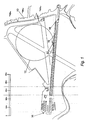
- Fig. 1 illustrates the layout of one example of a conventional spoolbase, located onshore adjacent a coastline 10, having a pipe storage loop 12 in accordance with the invention superimposed thereon.
- the conventional spoolbase comprises a main pipe welding plant 14, where individual joints of pipe are welded together to form stalks.
- the stalks are conventionally stored on pipe racks 16, which extend between the welding plant 14 and a tie-in welding station 18 adjacent the coastline 10.
- the pipe racks are approximately 1 kilometre in length.
- the stalks are spooled onto the storage reel of the pipelaying vessel (not shown) in the direction of the arrow A, tie-in welds being formed between subsequent stalks, at station 18, as spooling progresses.
- the pipe racks 16 of the conventional spoolbase are rendered redundant by the present invention.
- the storage loop 12 in accordance with the invention comprises a closed loop of rail track, having a plurality of interconnected rail bogies (or wagons or carriages) 100 (Figs. 2, 3 and 4) distributed about its circumference.
- the loop is preferably circular, as in this example, but may be non-circular so long as its radius of curvature is nowhere less than a predetermined minimum value selected to suit the maximum diameter of pipe which is to be accommodated.
- the minimum radius of curvature is selected such that the elastic yield limit of the pipe is not exceeded when the pipe is bent around the storage loop, and preferably such that the stresses imposed on the pipe do not exceed 72% of its yield limit.
- this requires a loop approximately 300 meters in diameter (ie. a radius of curvature not less than 150 meters). In the illustrated example, the loop has a diameter of 450 meters.
- the invention is not restricted to non-plastic bending of the stored pipe. It is also possible for the pipe to be bent plastically when wound onto the storage loop and to be straightened on removal, allowing the minimum radius of curvature of the loop to be reduced for a given pipe diameter. Straightening apparatus and methods for this purpose are well known from reel pipelay systems and will not be described further herein.
- Figs. 2 and 3 illustrate portions of the 450 meter diameter loop 12 of Fig. 1 in greater detail.
- Fig. 1 shows the location of two wagons 100 on the rail track 20.
- the wagons 100 will be spaced substantially equidistantly around the length of the loop. In this example the wagons 100 have a spacing of 18 meters between wagon centres. This would require seventy seven wagons for a 450 meter diameter loop.
- Fig. 3 shows an optional arrangement for sidings 22 extending into the interior of the loop 12, allowing wagons 100 to be taken out of the loop for servicing etc.
- the arrangement includes two individual sidings 24, 26 with points 28, 30 at the track junctions, as will be readily understood by those skilled in the art.
- the wagons 100 are adapted to receive and retain the pipeline such that, when the pipeline is secured to one of the wagons, the wagons may be driven around the loop 12 so as to wind the pipe onto a supporting surface provided by the wagons, so that multiple turns of the pipeline may be wrapped around the length of the loop.
- Fig. 4 illustrates the configuration of the wagons 100 and the disposition of the pipe 102 thereon, in use.
- the wagons 100 may be purpose built or may be converted from existing rolling stock, such as conventional hopper wagons.
- Each consists of two pairs of flanged wheels 104, mounted on respective axles 106 beneath a chassis 108, which engage the rails 109 of the track 20 in a well known manner.
- a horizontal pipe supporting deck 110 is mounted on the chassis, and vertical pipe retaining struts 112 are mounted on that side of the chassis 108 which will face the interior of the loop 12, in use.
- the struts 112 restrain inward movement of the pipe 102 when the pipe is wound onto the loop.
- the wraps of pipe 102 lie side by side on the deck 110.
- the wagon 100 accommodates 8 wraps of 40.6 centimetre (16 inch) pipe 102. For a 450 meter loop, this corresponds to a total pipeline length of about 11 kilometres.
- the pipeline contacting surfaces of the deck 110 and struts 112 may be faced with protective material, such as polymers or elastomers, to protect the pipe against damage.
- the deck 110 is faced with a 25 millimetre thickness of UHMW polyethylene 114, and the struts 112 with 'D' rubber 116.
- More than one layer of pipe may be wrapped on the loop. Additional layers may be continuations of the first layer, or may be comprise separate pipelines.
- a second layer 118 is shown comprising a separate 10 centimetre pipeline, separated from the first layer by means of timber battens 120.
- the wagons are preferably interconnected by means of rigid, elongate connecting members 122, such as lengths of steel pipe, connected to the wagons by suitable couplings 124.
- the conventional "instanter" rolling stock coupling is preferably replaced with a close tolerance coupling such as a clevis pin assembly, to prevent relative movement between wagons which might damage the pipe or pipe coatings.
- Conversion of standard rolling stock preferably also includes increasing the overall width and the track width, and lowering the suspension and deck height.
- the wagons may further be modified in view of the fact that they will always be travelling on a closed loop with in which the inside track is shorter in length than the outside track.
- the wheels of the wagons may be mounted on individual stub axles, rather than in pairs on conventional through-axles.
- the wagons 100 may be driven by a locomotive which may be purpose built or converted from an existing locomotive (the power sources of most commuter trains are below floor level, allowing a clear deck area above for supporting the pipe), preferably including conversion to an hydraulic power source.
- drive means may be incorporated into some of the wagons.
- hydraulic motors could be fitted to, say, every sixth wagon, each pump being electrically controlled from a central station communicating with each driven wagon via an RS 232 interface.
- Speed control would be achieved using a closed loop feedback system.
- the pipeline can be wound onto the storage loop as the pipeline fabrication proceeds. This could be done by assembling stalks and making tie in welds as the stalks are wound onto the loop, or directly from the main welding plant 14.
- the pipeline is to be transferred from the loop onto the reel of a pipelaying vessel, the end of the pipeline which was the trailing end during winding onto the storage loop becomes the leading end for spooling onto the vessel.
- the pipe supporting wagons would be driven in the same direction (counter-clockwise) for both winding the pipeline onto the loop and for spooling the pipeline from the loop onto the vessel.
- FIGs. 5 to 7 illustrate a preferred embodiment of the invention.
- a circular storage loop 212 is located adjacent the coastline 210.
- the main storage loop 212 may be substantially the same as that described above with reference to Figs. 1 to 4. In this case the sidings 22 have been omitted.
- the storage facility includes a pipe loading/offloading area 214 and an "expansion arc" 216, both of which are described in greater detail below.
- the expansion arc 216 leads from the loop 212 to a firing line 218 which extends along causeway 220 to the location where the pipelay vessel 222 is moored for loading.
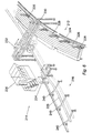
- Fig. 6 illustrates the loading/offloading area 214 of Fig. 5 in greater detail.
- Fig. 6 shows a portion of the storage loop 212 comprising track 224 with bogies or wagons 226 supporting multiple turns of pipe 228.
- a gantry 230 spans the track 224, extending outwith the loop 212 so as to overlie a pipe approach path which is approximately tangential to the track 224 at the point of loading/offloading.
- a "roller box" 232 Suspended beneath the gantry 230 for transverse movement along the length thereof is a "roller box" 232 through which the pipe 228 passes during loading or off loading.
- the roller box acts as a guide for the pipe and may include sensors for monitoring the position and orientation of the pipe.
- Pipe guides of this type are used in the laying of pipe from reel-type pipelay vessels such that as disclosed in US-A-4,269,540, and will not be described in greater detail herein. Transverse movement of the roller box 232 on the gantry 230 permits the pipe to be guided accurately during loading and unloading.
- a tensioning unit 234 Downstream of the roller box 232 in the direction of offloading is a tensioning unit 234 for controlling the tension on the pipeline during loading and offloading operations.
- the tensioning unit comprises a pair of roller track assemblies located on either side of the pipe and mounted for transverse movement with the roller box 232.
- Pipe tensioning apparatus of this type is well known in the field of marine pipelaying and will not be described in greater detail herein.
- the tensioner applies a degree of back tension to the pipe during loading and unloading and while the pipe is stored on the loop, so as to oppose the tendency of the bent pipe to spring outwardly. Typically, one or two tonnes of tension might be required.
- the tensioning unit 234 may also include means for straightening the pipe during offloading.
- the straightening means may comprise a three-point straightener of the type which is also well known in the field of marine pipelaying.
- the straightener and tensioner may be integrated into a single unit, as is also well known.
- a control cabin 236 houses the personnel and apparatus required to control the operation of the storage facility.
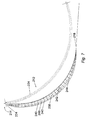
- the loading/offloading arrangement preferably includes an expansion arc 216 as seen in Fig. 5 and further illustrated in Figs. 6 and 7.
- the expansion arc 216 consists of a series of pipe supports defining an arcuate path of sufficient width to allow a nominal pipeline path 238 along the centre of the path to be lengthened or shortened in response to differential movements of the reel and the wagons.
- the expansion arc comprises a series of rollers 240 having their axes of rotation extending at right angles to the nominal pipeline path 238.
- the rollers 240 are suitably about 10 metres in length (i.e. the path is about 10 metres wide).
- the rollers 240 might be reduced in length towards either end of the expansion arc 216.
- Fig. 7 illustrates the maximum and minimum pipeline excursion routes 242 and 244 respectively along the expansion arc 216.
- the pipe is loaded and offloaded along the same path, so that the direction of movement of the wagons is reversed in each case.
- the fabrication of the pipeline for loading onto the loop may be carried out at a welding station (not shown) at any suitable location along the firing line 218.
- lengths of pipe may be assembled into stalks away from the firing line 218 prior to being transported to the firing line, tie-in welds being made between successive stalks before being spooled onto the storage loop.
Landscapes
- Engineering & Computer Science (AREA)
- General Engineering & Computer Science (AREA)
- Mechanical Engineering (AREA)
- Warehouses Or Storage Devices (AREA)
- Nonmetallic Welding Materials (AREA)
- Saccharide Compounds (AREA)
Claims (22)
- Rohrleitunglagerungsvorrichtung, bestehend aus einem geschlossenen Ring (12, 212) Schienenstrangs (oder etwas Gleichwertigem) (20, 224), der in einer im wesentlichen horizontalen Ebene liegt, einer Vielzahl von Schienen-Drehgestellen (100, 226), die auf dieser Schiene (20, 224) angebracht und auf diesem Ring (12, 212) verteilt sind und einem Mittel zum synchronen Fahren dieser Drehgestelle (100, 226) der Schiene (20, 224) entlang, wobei diese Drehgestelle (100, 226) ausgeführt sind, um eine Vielzahl von Kurven einer kontinuierlichen Länge einer Rohrleitung (102, 228), die sich um diesen Ring erstreckt aufzunehmen und zu halten und weiter bestehend aus einem Mittel zum Aufladen und Abladen der Rohrleitung (102, 228) in die und von den Drehgestellen (102, 226);
dadurch gekennzeichnet, daß: das Mittel zum Aufladen/Abladen des Rohrs so angeordnet ist, daß es einen im wesentlichen horizontalen auf das Rohr hinzu laufenden Weg (218) beschreibt, der bei der Auflade-/Abladestelle ungefähr tangential zu dem Ring (12, 212) liegt. - Vorrichtung gemäß Anspruch 1, wobei der Umfang des Rings (12, 212) kontinuierlich gekrümmt ist, so daß an jeder Stelle um dessen Umfang herum der Krümmungsradius des Rings (12, 212) größer als ein vorbestimmter Mindestwert ist.
- Vorrichtung gemäß Anspruch 2, wobei der kleinste Krümmungsradius des Rings (12, 212) so gewählt wird, daß bei einer Rohrleitung (102, 228) mit einem vorbestimmten Höchstdurchmesser, die auf der Vorrichtung gelagert werden soll, die Grenze der elastischen Ausweichfähigkeit jener Rohrleitung (102, 228) durch das Biegen der Rohrleitung (102, 228), um darauf gelagert zu werden, nicht überschritten wird.
- Vorrichtung gemäß Anspruch 2, wobei der kleinste Krümmungsradius so gewählt wird, daß die auf die Rohrleitung (102, 228) wirkenden Spannungen 72 % ihrer Grenze der elastischen Ausweichfähigkeit nicht überschreiten.
- Vorrichtung gemäß einem der vorhergehenden Ansprüche, wobei der Ring (12, 212) im wesentlichen kreisförmig ist und einen im wesentlichen konstanten Krümmungsradius aufweist.
- Vorrichtung gemäß einem der vorhergehenden Ansprüche, wobei die Drehgestelle (100, 226) in im wesentlichen gleichen Abständen voneinander auf dem Ring (12, 212) angeordnet sind.
- Vorrichtung gemäß Anspruch 6, wobei die Drehgestelle (100, 226) in einem Abstand voneinander angeordnet sind und anliegende Drehgestelle (100, 226) durch ein steifes, längliches Kupplungselement (122) miteinander verbunden sind.
- Vorrichtung gemäß Anspruch 7, wobei jedes der Kupplungselemente (122) an jeweils jedem Ende durch eine Drehanordnung (124) mit einer im wesentlichen vertikalen Drehachse mit einem entsprechenden Drehgestell verbunden ist.
- Vorrichtung gemäß einem der vorhergehenden Ansprüche, wobei der Mindestkrümmungsradius mindestens 150 Meter beträgt, so daß der maximale Durchmesser des Rohrs (102, 228), das auf der Vorrichtung gelagert werden kann, ohne daß die Spannungen 72 % der Grenze der elastischen Ausweichfähigkeit überschreiten, mindestens 40,6 Zentimeter (16 Inch) beträgt.
- Vorrichtung gemäß einem der vorhergehenden Ansprüche, wobei das Mittel zum Aufladen/Abladen des Rohrs eine Rohrhandhabungsvorrichtung zum Aufladen und Abladen der Rohre (102, 228) in den und von dem Ring (12, 212) umfaßt.
- Vorrichtung gemäß Anspruch 10, wobei die Rohrhandhabungsvorrichtung einen Rohrleitungsweg umfaßt, der sich von einer Auflade-/Abladestelle auf dem Ring zum Führen des Rohrs zu einer Schußlinie (218) hin erstreckt, welche sich zu einer Vertäuungsstelle für ein Rohrverlegungswasserfahrzeug (222) erstreckt.
- Vorrichtung gemäß Anspruch 11, wobei die Rohrhandhabungsvorrichtung ein Rohrführungsmittel (232) umfaßt, das von einer Signalbrücke (230) hinunterhängt, welche die Schiene (20, 224) und den an der Auflade-/Abladestelle befindlichen, oder daran anliegenden Rohrweg überquert, wobei das Rohrführungsmittel (232) zur quergerichteten Bewegung entlang der Signalbrücke (230) angebracht ist.
- Vorrichtung gemäß Anspruch 11 oder Anspruch 12, wobei die Rohrhandhabungsvorrichtung ferner ein Rohrfestspannmittel (234) umfaßt, das auf dem Rohrweg in Abwärtsrichtung hinsichtlich des Rohrführungsmittels (234) in Richtung des Rohrabladens angeordnet ist.
- Vorrichtung gemäß einem der Ansprüche 11 bis 13, wobei der Rohrweg einen Dehnungsbogenteil (216) genügender Breite umfaßt, um zu ermöglichen, daß die Länge des Rohrwegs sich als Reaktion auf differenzielle Bewegungen der Drehgestelle (100, 226) um die Schiene (20, 224) und eines Rads eines Rohrverlegungswasserfahrzeugs (222), auf welches das Rohr (102, 228) gespult wird, variieren kann.
- Vorrichtung gemäß Anspruch 14, wobei der Dehnungsbogen (216) eine Reihe von Rohrstützrollenelementen (240) umfaßt, die einem gekrümmten Weg (238) entlang angeordnet sind, wobei die Rollen (240) im wesentlichen horizontale Drehachsen aufweisen, die sich im wesentlichen radial hinsichtlich des gekrümmten Wegs (238) erstrecken.
- Ein Eisenbahn-Drehgestell (100, 226) zur Verwendung in der Vorrichtung gemäß Ansprüchen 1 bis 15, wobei das Drehgestell (100, 226) ein Rohrstützmittel (110) und ein Rohrhaltemittel (112) umfaßt, das an einer Seite des Rohrstützmittels (110) angeordnet ist, welches bei Gebrauch dem Inneren des Lagerrings (12, 212) gegenüberliegt.
- Eisenbahn-Drehgestell (100, 226) gemäß Anspruch 16, wobei die die Rohrleitung kontaktierenden Oberflächen des Stützmittels (110) und des Haltemittels (112) aus einem Schutzmaterial (114, 116) wie etwa Elastomer- oder Polymermaterial geformt sind oder mit diesem verkleidet sind.
- Vorrichtung gemäß einem der Ansprüche 1 bis 15, die eine Vielzahl von Eisenbahn-Drehgestellen (100, 226) gemäß Anspruch 16 oder Anspruch 17 verwendet, wobei die Drehgestelle (100, 226) bei Gebrauch miteinander durch steife, verlängerte Kupplungselemente (122) verbunden sind, welche mit engtolerierten Kupplungsanordnungen (124) an den Enden der Drehgestelle (100, 226) verbunden sind.
- Ein Verfahren zum Lagern einer Rohrleitung (102, 228) kontinuierlicher Länge, bestehend aus den folgenden Schritten:dadurch gekennzeichnet, daß: die Rohrleitung (102, 228) auf diese Drehgestelle (100, 226) geladen und von ihnen in einem im wesentlichen horizontalen auf das Rohr hinzu laufenden Weg (218), der bei der Auflade-/Abladestelle ungefähr tangential zu dem Ring (12, 212) liegt, abgeladen wird.Bereitstellen eines geschlossenen Rings (12, 212) Schienenstrangs (oder etwas Gleichwertigem) (20, 224), der auf einer im wesentlichen horizontalen Ebene liegt;Aufbringen einer Vielzahl von Eisenbahn-Drehgestellen (100, 226) auf dem Schienenstrang (20, 224), so daß die Drehgestelle (100, 226) um den Ring (12, 212) verteilt sind, wobei die Drehgestelle (100, 226) ausgeführt sind, um eine Vielzahl von Kurven einer kontinuierlichen Länge einer Rohrleitung (102, 228), die sich um diesen Ring (12, 212) erstreckt, aufzunehmen und zu halten;Befestigen eines ersten Endes einer Rohrleitung (102, 228) an einem der Drehgestelle (100, 226); undFühren der Drehgestelle (100, 226) synchron der Schiene (20, 224) entlang, so daß sich die Rohrleitung (102, 228) um den Ring (12, 212), der durch die Drehgestelle (100, 226) gestützt ist, erstreckt;
- Ein Verfahren gemäß Anspruch 19, wobei die Rohrleitung (102, 228) auf das Rohrstützmittel (110) der Drehgestelle (100, 226) gewickelt wird, wobei die erste Umhüllung des das Rohr anstoßenden Rohrhaltemittels (112) auf einer Seite des Rohrstützmittels (110) angeordnet ist, welches dem Inneren des Lagerrings (12, 212) gegenüberliegt, und nachfolgende Umhüllungen Seite an Seite auf dem Rohrleitungsstützmittel (110) liegen, welches eine erste Schicht Rohr bildet.
- Verfahren gemäß Anspruch 20, wobei zusätzliche Rohrschichten über die erste Schicht gewickelt werden, wobei die Schichten durch Leisten getrennt sind.
- Verfahren gemäß Anspruch 21, wobei die zusätzlichen Schichten Rohrlängen unterschiedlicher Durchmesser umfassen.
Applications Claiming Priority (3)
| Application Number | Priority Date | Filing Date | Title |
|---|---|---|---|
| GBGB9608667.3A GB9608667D0 (en) | 1996-04-26 | 1996-04-26 | Pipeline storage |
| GB9608667 | 1996-04-26 | ||
| PCT/GB1997/001130 WO1997041054A1 (en) | 1996-04-26 | 1997-04-24 | Pipeline storage |
Publications (2)
| Publication Number | Publication Date |
|---|---|
| EP0909254A1 EP0909254A1 (de) | 1999-04-21 |
| EP0909254B1 true EP0909254B1 (de) | 2002-03-13 |
Family
ID=10792696
Family Applications (1)
| Application Number | Title | Priority Date | Filing Date |
|---|---|---|---|
| EP97919538A Expired - Lifetime EP0909254B1 (de) | 1996-04-26 | 1997-04-24 | Lager für rohre |
Country Status (7)
| Country | Link |
|---|---|
| US (1) | US6089489A (de) |
| EP (1) | EP0909254B1 (de) |
| AU (1) | AU719734B2 (de) |
| BR (1) | BR9708860A (de) |
| GB (1) | GB9608667D0 (de) |
| NO (1) | NO311177B1 (de) |
| WO (1) | WO1997041054A1 (de) |
Families Citing this family (14)
| Publication number | Priority date | Publication date | Assignee | Title |
|---|---|---|---|---|
| DK1104525T3 (da) * | 1998-08-20 | 2002-06-17 | Bogey Venlo B V | Fremgangsmåde og organ til opbevaring og/eller transport af et langstrakt rør eller kabel |
| US6554538B2 (en) | 2001-07-03 | 2003-04-29 | Torch Offshore, Inc. | Reel type pipeline laying ship and method |
| US6702519B2 (en) | 2001-07-03 | 2004-03-09 | Torch Offshore, Inc. | Reel type pipeline laying ship and method |
| US6733208B2 (en) | 2001-07-03 | 2004-05-11 | Torch Offshore, Inc. | Reel type pipeline laying ship and method |
| US6761505B2 (en) | 2002-01-15 | 2004-07-13 | Torch Offshore, Inc. | Reel type pipeline laying ship and method |
| FR2849486B1 (fr) | 2002-12-30 | 2005-08-26 | Technip Coflexip | Installation de fabrication des conduites tubulaires rigides enroulees |
| US7568650B2 (en) * | 2005-04-20 | 2009-08-04 | Kore Gear, Inc. | Level wind mechanism |
| NL1033123C1 (nl) * | 2006-12-22 | 2008-06-24 | Remko Luyten | Pijpleidingopslagsysteem. |
| GB0702161D0 (en) * | 2007-02-05 | 2007-03-14 | Technip France | Method and apparatus for laying a marine pipeline |
| US7927040B2 (en) * | 2008-08-08 | 2011-04-19 | Wilson Michael W N | Method for storing, delivering and spooling preassembled pipelines |
| NL1038286C2 (nl) * | 2010-10-03 | 2012-04-05 | Buijvoets Beheer Bv | Drukverdeler voor een pijpleiding. |
| GB2498187B (en) | 2012-01-03 | 2013-11-20 | Subsea 7 Ltd | Floatable spoolbase with intermediate carousel storage |
| WO2017193217A1 (en) * | 2016-05-11 | 2017-11-16 | Warrior Rig Technologies Limited | Continuous drilling system |
| US11781675B2 (en) | 2019-03-22 | 2023-10-10 | Paulo Roberto Gomes Fernandes | Method for manufacture, assembly and continuous construction of pipe sections in a spoolbase with gradual movement |
Family Cites Families (6)
| Publication number | Priority date | Publication date | Assignee | Title |
|---|---|---|---|---|
| GB925432A (de) * | 1960-07-19 | |||
| US3724567A (en) * | 1970-11-30 | 1973-04-03 | E Smitherman | Apparatus for handling column of drill pipe or tubing during drilling or workover operations |
| US3941146A (en) * | 1971-06-29 | 1976-03-02 | Institut Francaise Du Petrole, Des Carburants Et Lubrifiants | Apparatus for storing a flexible elongated member, such as a flexible drill column |
| FR2151467A5 (de) * | 1971-08-27 | 1973-04-20 | Inst Francais Du Petrole | |
| US3955593A (en) * | 1974-04-23 | 1976-05-11 | Continental Oil Company | Conveyor for flexible slurry hose |
| US5421501A (en) * | 1991-01-16 | 1995-06-06 | Haines; Roger C. | Method and apparatus for cable dispensing and placement |
-
1996
- 1996-04-26 GB GBGB9608667.3A patent/GB9608667D0/en active Pending
-
1997
- 1997-04-24 BR BR9708860A patent/BR9708860A/pt not_active IP Right Cessation
- 1997-04-24 WO PCT/GB1997/001130 patent/WO1997041054A1/en not_active Ceased
- 1997-04-24 US US09/171,828 patent/US6089489A/en not_active Expired - Lifetime
- 1997-04-24 EP EP97919538A patent/EP0909254B1/de not_active Expired - Lifetime
- 1997-04-24 AU AU23974/97A patent/AU719734B2/en not_active Ceased
-
1998
- 1998-10-23 NO NO19984943A patent/NO311177B1/no not_active IP Right Cessation
Also Published As
| Publication number | Publication date |
|---|---|
| BR9708860A (pt) | 1999-08-03 |
| NO984943L (no) | 1998-10-23 |
| WO1997041054A1 (en) | 1997-11-06 |
| NO311177B1 (no) | 2001-10-22 |
| US6089489A (en) | 2000-07-18 |
| NO984943D0 (no) | 1998-10-23 |
| AU719734B2 (en) | 2000-05-18 |
| EP0909254A1 (de) | 1999-04-21 |
| AU2397497A (en) | 1997-11-19 |
| GB9608667D0 (en) | 1996-07-03 |
Similar Documents
| Publication | Publication Date | Title |
|---|---|---|
| EP0909254B1 (de) | Lager für rohre | |
| EP2622248B1 (de) | Vorrichtung und verfahren zum auslegen eines länglichen artikels aus einem gefäss | |
| US6328502B1 (en) | Horizontal reel barge | |
| US5573353A (en) | Vertical reel pipe laying vessel | |
| US5971666A (en) | Pipe laying vessel | |
| US3965713A (en) | Method and apparatus for laying continuous pipe | |
| US4260287A (en) | Portable reel pipelaying method | |
| USRE30846E (en) | Submarine pipeline laying vessel | |
| BRPI0912068B1 (pt) | Método e sistema para armazenamento, enrolamento e distribuição de uma tubulação | |
| US4659253A (en) | Deep water cable laying method using buoyancy materials | |
| AU2008288297A1 (en) | Methods and apparatus for transferring and laying elongate articles at sea | |
| EP2363624B1 (de) | Landemechanismus für eine angehobene Rohrrolle | |
| EP2800686B1 (de) | Verlegen von leitungen auf see mit horizontalen spulen | |
| CA2252785C (en) | Pipeline storage | |
| US20120148348A1 (en) | System for reeling pipeline | |
| GB2265685A (en) | Laying pipe and cable under water | |
| EP0868621B1 (de) | Überführung von rohren mit grossem durchmesser von einer rolle auf eine andere | |
| NL2012137C2 (en) | Manufacturing of a subsea pipeline and spooling said pipeline onto a reel of a pipelaying vessel at a spoolbase. | |
| WO2026053036A1 (en) | Axial transport of coilable tubing | |
| GB1601730A (en) | Method of spooling pipe or a reel | |
| GB2316147A (en) | Pipe laying vessel with reel and diverter structure | |
| GB2286648A (en) | Pipelaying vessel |
Legal Events
| Date | Code | Title | Description |
|---|---|---|---|
| PUAI | Public reference made under article 153(3) epc to a published international application that has entered the european phase |
Free format text: ORIGINAL CODE: 0009012 |
|
| 17P | Request for examination filed |
Effective date: 19980925 |
|
| AK | Designated contracting states |
Kind code of ref document: A1 Designated state(s): GB |
|
| 17Q | First examination report despatched |
Effective date: 20000901 |
|
| GRAG | Despatch of communication of intention to grant |
Free format text: ORIGINAL CODE: EPIDOS AGRA |
|
| GRAG | Despatch of communication of intention to grant |
Free format text: ORIGINAL CODE: EPIDOS AGRA |
|
| GRAH | Despatch of communication of intention to grant a patent |
Free format text: ORIGINAL CODE: EPIDOS IGRA |
|
| GRAH | Despatch of communication of intention to grant a patent |
Free format text: ORIGINAL CODE: EPIDOS IGRA |
|
| REG | Reference to a national code |
Ref country code: GB Ref legal event code: IF02 |
|
| GRAA | (expected) grant |
Free format text: ORIGINAL CODE: 0009210 |
|
| AK | Designated contracting states |
Kind code of ref document: B1 Designated state(s): GB |
|
| PLBE | No opposition filed within time limit |
Free format text: ORIGINAL CODE: 0009261 |
|
| STAA | Information on the status of an ep patent application or granted ep patent |
Free format text: STATUS: NO OPPOSITION FILED WITHIN TIME LIMIT |
|
| 26N | No opposition filed |
Effective date: 20021216 |
|
| PGFP | Annual fee paid to national office [announced via postgrant information from national office to epo] |
Ref country code: GB Payment date: 20150414 Year of fee payment: 19 |
|
| GBPC | Gb: european patent ceased through non-payment of renewal fee |
Effective date: 20160424 |
|
| PG25 | Lapsed in a contracting state [announced via postgrant information from national office to epo] |
Ref country code: GB Free format text: LAPSE BECAUSE OF NON-PAYMENT OF DUE FEES Effective date: 20160424 |