EP0909554B1 - Prothèse d'oreille moyenne - Google Patents
Prothèse d'oreille moyenne Download PDFInfo
- Publication number
- EP0909554B1 EP0909554B1 EP98420182A EP98420182A EP0909554B1 EP 0909554 B1 EP0909554 B1 EP 0909554B1 EP 98420182 A EP98420182 A EP 98420182A EP 98420182 A EP98420182 A EP 98420182A EP 0909554 B1 EP0909554 B1 EP 0909554B1
- Authority
- EP
- European Patent Office
- Prior art keywords
- prosthesis
- wing
- prosthesis according
- stirrup
- alloy
- Prior art date
- Legal status (The legal status is an assumption and is not a legal conclusion. Google has not performed a legal analysis and makes no representation as to the accuracy of the status listed.)
- Expired - Lifetime
Links
- 210000000959 ear middle Anatomy 0.000 title claims description 12
- 210000003454 tympanic membrane Anatomy 0.000 claims description 19
- 210000000056 organ Anatomy 0.000 claims description 16
- PXHVJJICTQNCMI-UHFFFAOYSA-N Nickel Chemical compound [Ni] PXHVJJICTQNCMI-UHFFFAOYSA-N 0.000 claims description 10
- 229910045601 alloy Inorganic materials 0.000 claims description 8
- 239000000956 alloy Substances 0.000 claims description 8
- 229910001285 shape-memory alloy Inorganic materials 0.000 claims description 8
- 229910052759 nickel Inorganic materials 0.000 claims description 5
- RTAQQCXQSZGOHL-UHFFFAOYSA-N Titanium Chemical compound [Ti] RTAQQCXQSZGOHL-UHFFFAOYSA-N 0.000 claims description 3
- 230000036760 body temperature Effects 0.000 claims description 3
- 229910001092 metal group alloy Inorganic materials 0.000 claims description 3
- 239000010936 titanium Substances 0.000 claims description 3
- 229910052719 titanium Inorganic materials 0.000 claims description 3
- 210000003128 head Anatomy 0.000 description 8
- BASFCYQUMIYNBI-UHFFFAOYSA-N platinum Chemical compound [Pt] BASFCYQUMIYNBI-UHFFFAOYSA-N 0.000 description 8
- 230000007547 defect Effects 0.000 description 5
- 230000006870 function Effects 0.000 description 5
- 229910000734 martensite Inorganic materials 0.000 description 5
- 230000005540 biological transmission Effects 0.000 description 4
- 210000003027 ear inner Anatomy 0.000 description 4
- 238000009434 installation Methods 0.000 description 4
- 229910052697 platinum Inorganic materials 0.000 description 4
- 239000000470 constituent Substances 0.000 description 3
- 239000000463 material Substances 0.000 description 3
- 230000002980 postoperative effect Effects 0.000 description 3
- 206010016654 Fibrosis Diseases 0.000 description 2
- 230000008859 change Effects 0.000 description 2
- 238000006243 chemical reaction Methods 0.000 description 2
- 210000000613 ear canal Anatomy 0.000 description 2
- 230000004761 fibrosis Effects 0.000 description 2
- 239000012634 fragment Substances 0.000 description 2
- 239000007788 liquid Substances 0.000 description 2
- 206010011878 Deafness Diseases 0.000 description 1
- 206010011985 Decubitus ulcer Diseases 0.000 description 1
- 206010061218 Inflammation Diseases 0.000 description 1
- 238000004873 anchoring Methods 0.000 description 1
- 230000008901 benefit Effects 0.000 description 1
- 210000000988 bone and bone Anatomy 0.000 description 1
- 210000000845 cartilage Anatomy 0.000 description 1
- 239000000919 ceramic Substances 0.000 description 1
- 239000013078 crystal Substances 0.000 description 1
- 230000006378 damage Effects 0.000 description 1
- 238000006073 displacement reaction Methods 0.000 description 1
- 210000000883 ear external Anatomy 0.000 description 1
- 230000000694 effects Effects 0.000 description 1
- 230000010370 hearing loss Effects 0.000 description 1
- 231100000888 hearing loss Toxicity 0.000 description 1
- 208000016354 hearing loss disease Diseases 0.000 description 1
- 230000001939 inductive effect Effects 0.000 description 1
- 230000002757 inflammatory effect Effects 0.000 description 1
- 230000004054 inflammatory process Effects 0.000 description 1
- 208000014674 injury Diseases 0.000 description 1
- 210000003041 ligament Anatomy 0.000 description 1
- 230000007774 longterm Effects 0.000 description 1
- 238000012423 maintenance Methods 0.000 description 1
- 229910052751 metal Inorganic materials 0.000 description 1
- 239000002184 metal Substances 0.000 description 1
- 150000002739 metals Chemical class 0.000 description 1
- 238000000034 method Methods 0.000 description 1
- 238000003801 milling Methods 0.000 description 1
- 230000007170 pathology Effects 0.000 description 1
- 230000008569 process Effects 0.000 description 1
- 230000000284 resting effect Effects 0.000 description 1
- 210000001519 tissue Anatomy 0.000 description 1
- 230000007704 transition Effects 0.000 description 1
- 230000008733 trauma Effects 0.000 description 1
- 210000001213 vestibule labyrinth Anatomy 0.000 description 1
- 230000003313 weakening effect Effects 0.000 description 1
Images

Classifications
-
- A—HUMAN NECESSITIES
- A61—MEDICAL OR VETERINARY SCIENCE; HYGIENE
- A61F—FILTERS IMPLANTABLE INTO BLOOD VESSELS; PROSTHESES; DEVICES PROVIDING PATENCY TO, OR PREVENTING COLLAPSING OF, TUBULAR STRUCTURES OF THE BODY, e.g. STENTS; ORTHOPAEDIC, NURSING OR CONTRACEPTIVE DEVICES; FOMENTATION; TREATMENT OR PROTECTION OF EYES OR EARS; BANDAGES, DRESSINGS OR ABSORBENT PADS; FIRST-AID KITS
- A61F2/00—Filters implantable into blood vessels; Prostheses, i.e. artificial substitutes or replacements for parts of the body; Appliances for connecting them with the body; Devices providing patency to, or preventing collapsing of, tubular structures of the body, e.g. stents
- A61F2/02—Prostheses implantable into the body
- A61F2/18—Internal ear or nose parts, e.g. ear-drums
- A61F2002/183—Ear parts
-
- A—HUMAN NECESSITIES
- A61—MEDICAL OR VETERINARY SCIENCE; HYGIENE
- A61F—FILTERS IMPLANTABLE INTO BLOOD VESSELS; PROSTHESES; DEVICES PROVIDING PATENCY TO, OR PREVENTING COLLAPSING OF, TUBULAR STRUCTURES OF THE BODY, e.g. STENTS; ORTHOPAEDIC, NURSING OR CONTRACEPTIVE DEVICES; FOMENTATION; TREATMENT OR PROTECTION OF EYES OR EARS; BANDAGES, DRESSINGS OR ABSORBENT PADS; FIRST-AID KITS
- A61F2210/00—Particular material properties of prostheses classified in groups A61F2/00 - A61F2/26 or A61F2/82 or A61F9/00 or A61F11/00 or subgroups thereof
- A61F2210/0014—Particular material properties of prostheses classified in groups A61F2/00 - A61F2/26 or A61F2/82 or A61F9/00 or A61F11/00 or subgroups thereof using shape memory or superelastic materials, e.g. nitinol
Definitions
- the present invention relates to an ossicular prosthesis of the middle ear, of the type intended to replace at least partially the ossicular chain and to connect a first organ, in particular the stirrup plate or the stirrup, with a second organ, in particular the hammer or the eardrum, said prosthesis being able to self-adjust by elasticity.
- the middle ear is intended to transmit vibrations sound reaching the eardrum from an air environment, down to a liquid medium, namely the inner ear, which constitutes a receiving organ for receiving a sound wave.
- tympanoossicular system composed a tympanic membrane adjoining an ossicular chain formed, from outside inside, of the hammer, anvil and stirrup.
- the tympanic membrane is attached to this chain through the hammer handle.
- the stirrup rests on a plate which comes into contact, through its internal base, with the liquid medium, also called labyrinthine medium, of the inner ear.
- the function of the ossicles in the ossicular chain is to ensure contact between the eardrum and this labyrinthine environment, which constitutes the columellar effect.
- the tympano-ossicular system is suspended in the air cavity of the ear average. There is therefore no direct contact with this system with the bone walls, in order to convey all of the acoustic energy coming from the tympanic membrane, know from the outer ear, toward the inner ear.
- the tympano-ossicular system is fixed two annular ligaments arranged at its ends, namely that of the tympanic membrane and that of the platinum stirrup.
- the subject of the invention is the correction of hearing loss in transmission, i.e. those resulting from breaches of the ossicular chain following various pathologies.
- Middle ear ossicular prostheses are intended to at least partially replace this chain ossicular, i.e. either only the anvil or the stirrup and the anvil, or even the stirrup, the anvil and the hammer.
- prostheses that are made in different materials such as ceramic, and consist a rod resting on the stirrup or on its plate, surmounted by a plate which rests under the handle of the hammer or the tympanum. These prostheses have a structure essentially rigid, due to the nature of their constituent material.
- FR-A-2 691 354 shows a prosthesis according to the preamble of claim 1.
- the invention proposes to overcome the drawbacks of the prior art mentioned above.
- ear prosthesis average of the type known from FR-A-2 691 354 characterized by the characteristics of the characterizing part of claim 1.
- elongated element notably designates an element formed at least partially by a thin strip.
- the prosthesis according to the invention makes it possible to perform the previously mentioned objectives. So it presents a extremely simple mechanical structure, since it is formed by a single element which must not be cut or milled during its installation, which reduces the risk of reaction inflammatory and lyses phenomena.
- this curved part has flexibility sufficient, so that it can be installed without excessive tension during its installation, and that it can exert a when placed, an almost constant permanent tension at the level of its respective anchor points.
- the curved part is intended to come into contact with first and second organs, by the external surface of its two wings.
- the conforming prosthesis to the invention constitutes an anvil prosthesis allowing connect the hammer and the stirrup.
- a notch intended to receive the button of the stirrup is formed in the second wing of the curved portion. This guarantees a satisfactory long-term anchoring of the whole of the prosthesis with the stirrup.
- the curved portion is intended to come into contact with one of the organs by the outer surface of a first wing, and it is extended, at the level of a second wing, by a portion substantially straight.
- This substantially straight portion allows the prosthesis according to the invention to rest on the caliper plate, so that it is able to constitute a total prosthesis of anvil and stirrup or else still hammer, anvil and stirrup.
- This portion rectilinear also assumes a function of transmission of sound vibrations, up to the caliper plate.
- the straight portion is arranged substantially in the extension of the second wing while, for a total prosthesis, the rectilinear portion is roughly perpendicular to this second wing.
- the rectilinear portion is extended, at its end opposite to the curved portion, by a bent portion. This last is supported on the caliper plate, and guarantees good stability of the prosthesis relative to the latter.
- the curved portion is extended, at its first wing, by a curved portion whose concavity is directed to the opposite of the straight portion.
- This curved portion ensures satisfactory maintenance of the prosthesis on the first organ that it is intended to connect, namely the eardrum or the hammer.
- the prosthesis is made of a superelastic metal alloy at body temperature.
- superelastic alloy is meant any alloy whose elasticity range is larger than that of conventional metals, and for which the force exerted on the level of elasticity is practically constant.
- the superelastic alloy is a shape memory alloy.
- a shape memory alloy present on both sides of a transition temperature, a crystal structure hot stable austenitic and martensitic structure cold stable.
- a piece made in one shape memory alloy is stressed, in its austenitic structure, it sees its structure becoming at least partially martensitic, which leads to deformation very high elasticity of up to 8%.
- the curved part absorbs alone all the constraints, during installation by adjusting its dimensions.
- this curved part adapts its geometry depending on the size of the defect or "defect”, at know the elements of the ossicular chain that it is intended to replace. Due to its superelastic nature, this curved part exerts on the eardrum a very weak force and substantially constant, which is particularly advantageous with regard to the physiological integrity of the eardrum and the platinum.
- the shape memory alloy has an austenitic end temperature (A f ) without mechanical stress, which is less than 30 ° C and, preferably, less than 20 ° C .
- the shape memory alloy consists of titanium and nickel, and it contains 55.7% ⁇ 0.4% nickel.
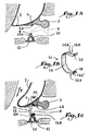
- Figure 1A shows the middle ear of a patient. It includes, from outside inside, a tympanum 2 adjoining the hammer 3 by its handle 4.
- the hammer head has, in rear, a joint surface which is intended to unite with anvil 6 whose lenticular process articulates with the head 8 of the caliper 10.
- the internal base of the plate 12 of the stirrup is directed towards the floor of the vestibule of the ear internal not shown.
- the ossicular chain composed of the hammer, the anvil and the stirrup, is incomplete insofar as the anvil 6 is absent and is therefore represented by lines interrupted.
- the head of the patient is in the operating position, i.e. decubitus dorsal, head turned to the side opposite the ear shown, here the left ear.
- FIG. 1B represents a prosthesis designated in its together by reference 14 and intended to replace the anvil 6 within the ossicular chain of Figure 1A.
- This prosthesis is made of a memory alloy of form composed of 55.75% nickel and 44.25% titanium, of which the structure is superelastic at body temperature.
- This prosthesis 14 comprises a curved portion 16 substantially C-shaped with the lower wing 16A provided a through notch 18, and the upper wing 16B is extended by a curved portion 20 whose concavity is directed opposite the lower wing 16A intended to enter in contact with the handle 4 of the hammer.
- the distance between the two wings 16A, 16B is slightly greater than that separating the head 8 from the stirrup by relative to the lower surface of handle 4 of the hammer.
- the outer surface 16B ' of the upper wing 16B rests, once the prosthesis is mounted, against the lower surface 4A of the handle 4.
- the outer surface 16A ′ of the lower wing 16A enters contact with the upper surface 10A of the stirrup 10, the notch 18 of this wing 16A fitting onto the head 8 of the stirrup.
- the prosthesis according to the invention is applied in a known manner either via the external auditory canal, or endaural route, according to arrow F, either via the posterior tympanotomy according to arrow F '.
- the surgeon places the orifice 18 on the head 8 of the stirrup.
- the superelastic nature of the alloy used makes it possible to bend the prosthesis so as to bring its wings 16A together and 16B, which makes it easy to slide the upper wing 16B under the handle 4 of the hammer.
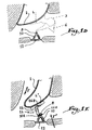
- the prosthesis 14 according to the invention can also be used in the case where the hammer is absent, Figure 1D represents the incomplete ossicular chain since the anvil and the hammer are absent and are therefore found shown in broken lines.
- prosthesis 14 The fitting of prosthesis 14 according to the invention on the head 8 of the stirrup is identical to what has just been described.
- the hammer 4 is replaced by a cartilaginous fragment 4 ' intended to come into contact with the upper wing 16B of the prosthesis 14.
- the geometry of the curved portion 20 guarantees a perfect complementarity of shapes between handle 4 or cartilage fragment 4 'and the prosthesis.
- the superelastic nature of the latter allows it to adjust not only according to the sizes of the defects of the different patients, but still depending on the forces exerted by the stirrup and the hammer.
- the ossicular chain shown in Figure 2A differs of that illustrated in Figure 1A in that not only the anvil 106, but also the arch of the stirrup 110 are absent and therefore represented in broken lines.
- the prosthesis 114 shown in FIG. 2B and intended to replace these two members, comprises a curved portion 116 substantially in form of C, of which a first wing 116B, or distal wing is extended by a curved portion 120 substantially similar to that 20 illustrated in FIGS. 1B and 1C.
- the second wing 116A of this curved portion 116, or proximal wing continues with a substantially rectilinear portion 122 oriented along the extension of this lower wing 116A.
- This portion straight 122 is terminated by a bent portion 124 making projection towards the core 116C of the curved portion, substantially at a right angle from the portion straight 122.
- the distance between the outer surface 116B 'of the wing distal 116B, and the lower surface 124A of the portion angled 124, is slightly greater than the distance between the plate 112 and the lower surface 104A of the handle 104 of the hammer 103.
- the prosthesis 114 is assembled by placing the lower surface 124A of the bent portion 124 on the plate 112, then bringing the distal wing 116B closer to the portion curved 116 towards the proximal wing 116A, thanks to the nature of the superelastic material used.
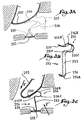
- the curved portion 116 Since the curved portion 116 is subjected to the stresses exerted by the hammer and the plate of the stirrup, it has an at least partially martensitic structure. Its wings 116A, 116B can therefore be adjusted as a function the size of the ossicular chains of the different patients and forces exerted on the hammer and the plate 112 of the stirrup during wicking or post-operative fibrosis, this which gives excellent stability to the prosthesis.
- the rectilinear portion 122 for its part, has a austenitic structure, which gives it rigidity allowing to transmit sound vibrations from the tympanum 102 to the labyrinthine middle of the inner ear.
- the middle ear shown in Figure 3A is completely devoid of ossicular chain, since at the same time the hammer 203, the anvil 206 and the entire structure of the stirrup 210 are absent, and are therefore represented by broken lines.
- Prosthesis 214 is intended to replace all of this ossicular chain. It includes a curved portion 216 substantially C-shaped, with the upper wing 216B ends with a curved portion 220 whose concavity is directed away from the lower wing 216A of the portion curved. This lower wing 216A is extended by a portion straight 222 connecting to the curved portion, substantially at a right angle. This straight portion 222 is finished by a bent portion 224 operating a step substantially at a right angle, and projecting in the opposite direction to the core 216C of the curved portion.
- the distance between the outer surface 216B 'of the wing upper 216B, and the lower surface 224A of the portion angled 224, is slightly larger than that separating the eardrum 202 of the plate 212.
- the prosthesis 214 is mounted in a similar manner to what has been described in FIGS. 2A to 2C, either according to the arrow F via the external auditory canal, either according to the arrow F 'via the posterior tympanotomy.
- the surgeon brings wings 216A, 216B together, taking advantage of nature superelastic of the constituent alloy of the prosthesis, which allows the latter to be inserted without damaging or platinum, nor the eardrum.
- the prosthesis rests against the tympanum 202, both by its upper wing 216B and its curved portion 220 whose geometry ensures perfect complementarity of forms with the eardrum.
- the prosthesis rests, by the lower surface 224A of its bent portion 224, on the plate 212 of the stirrup.
- the curved portion 216 is subjected to the forces exerted by the eardrum and the stirrup plate and has a structure austenitic or at least partially martensitic, in depending on the intensity of these efforts.
- the dimensions of this curved portion 216 are then likely to adjust to the times depending on the size of the different ossicular defects of patients, and the efforts exerted on this portion both the eardrum and the stirrup plate. Note that, due to its superelastic nature, the forces exerted in reaction, on the eardrum and the stirrup plate, respectively by the curved portion and by the curved portion, are very weak and substantially constant. This is particularly advantageous for preserving the physiological integrity of the eardrum and platinum, and to provide satisfactory stability of the ossicular chain thus reconstructed.
- the straight portion 222 which has a austenitic structure, is able to assume in a way satisfactory vibration transmission function sound thanks to its stiffness properties.
Landscapes
- Health & Medical Sciences (AREA)
- Otolaryngology (AREA)
- Pulmonology (AREA)
- Cardiology (AREA)
- Oral & Maxillofacial Surgery (AREA)
- Transplantation (AREA)
- Engineering & Computer Science (AREA)
- Biomedical Technology (AREA)
- Heart & Thoracic Surgery (AREA)
- Vascular Medicine (AREA)
- Life Sciences & Earth Sciences (AREA)
- Animal Behavior & Ethology (AREA)
- General Health & Medical Sciences (AREA)
- Public Health (AREA)
- Veterinary Medicine (AREA)
- Prostheses (AREA)
Description
- la figure 1A représente une chaíne ossiculaire incomplète, dans laquelle l'enclume est absente ;
- la figure 1B représente une première prothèse conforme à l'invention ;
- la figure 1C représente la prothèse illustrée à la figure 1B, insérée au sein de la chaíne ossiculaire de la figure 1A ;
- la figure 1D représente une chaíne ossiculaire incomplète, dans laquelle l'enclume et le marteau sont absents ;
- la figure 1E représente la prothèse illustrée à la figure 1B, insérée au sein de la chaíne ossiculaire de la figure 1D ;
- la figure 2A représente une chaíne ossiculaire incomplète, dans laquelle l'étrier et l'enclume sont absents ;
- la figure 2B illustre, en perspective, une deuxième prothèse conforme à l'invention ;
- la figure 2C illustre la prothèse représentée à la figure 2B, insérée au sein de la chaíne ossiculaire de la figure 2A ;
- la figure 3A représente, en pointillés, une chaíne ossiculaire totalement absente ;
- la figure 3B illustre une troisième prothèse conforme à l'invention, et
- la figure 3C représente la prothèse illustrée à la figure 3B et remplaçant la chaíne ossiculaire de la figure 3A.
Claims (10)
- Prothèse (14 ; 114 ; 214) ossiculaire de l'oreille moyenne, du type destinée à remplacer au moins partiellement la chaíne ossiculaire (3, 6, 10 ; 103, 106, 110 ; 203, 206, 210) et à relier un premier organe, notamment la platine de l'étrier ou l'étrier, avec un second organe, notamment le marteau ou le tympan, ladite prothèse étant apte à s'auto-ajuster par élasticité, ladite prothèse étant formée par un élément allongé qui comprend une portion cintrée (16 ; 116 ; 216) présentant sensiblement une forme de C, dont les ailes sont aptes à se rapprocher et à s'éloigner mutuellement par élasticité, caractérisée en ce que ladite portion cintrée est destinée à entrer en contact avec au moins un desdits organes par une surface extérieure (16A', 16B' ; 116B' ; 216B') d'au moins une (16A, 16B ; 116B ; 216B) de ses ailes (16A, 16B ; 116A, 116B ; 216A, 216B).
- Prothèse selon la revendication 1, caractérisée en ce que ladite portion cintrée (16) est destinée à entrer en contact avec lesdits premier et second organes par la surface extérieure (16A', 16B') de ses deux ailes (16A, 16B).
- Prothèse selon la revendication 1 ou 2, caractérisée en ce qu'une encoche (18) destinée à recevoir le bouton (8) de l'étrier (10), est ménagée dans ladite seconde aile (16A) de ladite portion cintrée (16).
- Prothèse selon la revendication 1, caractérisée en ce que ladite portion cintrée (116 ; 216) est destinée à entrer en contact avec un desdits organes par la surface extérieure (116B', 216B') d'une première aile (116B ; 216B) et est prolongée, au niveau d'une seconde aile (116A ; 216A), par une portion sensiblement rectiligne (122 ; 222).
- Prothèse selon la revendication 4, caractérisée en ce que ladite portion rectiligne (122 ; 222) est prolongée, à son extrémité opposée à la portion cintrée (116 ; 216), par une portion coudée (124 ; 224) destinée à être supportée par la platine de l'étrier.
- Prothèse selon l'une quelconque des revendications 1 à 5, caractérisée en ce que ladite portion cintrée (16) est prolongée, au niveau d'une première aile (16B), par une portion galbée (20) dont la concavité est dirigée à l'opposé d'une seconde aile (16A) de ladite portion cintrée (16).
- Prothèse selon l'une des revendications 1 à 6, caractérisée en ce qu'elle est réalisée en un alliage métallique superélastique à la température du corps.
- Prothèse selon la revendication 7, caractérisée en ce que ledit alliage superélastique est un alliage à mémoire de forme.
- Prothèse selon la revendication 8, caractérisée en ce que ledit alliage possède une température de fin d'apparition austénitique (Af) sans contrainte mécanique, qui est inférieure à 30°C et, de préférence, inférieure à 20°C.
- Prothèse selon la revendication 8 ou 9, caractérisée en ce que ledit alliage se compose de titane et de nickel, et en ce qu'il contient 55,7% ± 0,4% de nickel.
Applications Claiming Priority (2)
| Application Number | Priority Date | Filing Date | Title |
|---|---|---|---|
| FR9712995A FR2769492B1 (fr) | 1997-10-10 | 1997-10-10 | Prothese d'oreille moyenne |
| FR9712995 | 1997-10-10 |
Publications (2)
| Publication Number | Publication Date |
|---|---|
| EP0909554A1 EP0909554A1 (fr) | 1999-04-21 |
| EP0909554B1 true EP0909554B1 (fr) | 2003-01-22 |
Family
ID=9512334
Family Applications (1)
| Application Number | Title | Priority Date | Filing Date |
|---|---|---|---|
| EP98420182A Expired - Lifetime EP0909554B1 (fr) | 1997-10-10 | 1998-10-09 | Prothèse d'oreille moyenne |
Country Status (4)
| Country | Link |
|---|---|
| US (1) | US6203571B1 (fr) |
| EP (1) | EP0909554B1 (fr) |
| DE (1) | DE69810867D1 (fr) |
| FR (1) | FR2769492B1 (fr) |
Families Citing this family (17)
| Publication number | Priority date | Publication date | Assignee | Title |
|---|---|---|---|---|
| US6554861B2 (en) * | 1999-01-19 | 2003-04-29 | Gyrus Ent L.L.C. | Otologic prosthesis |
| US6197060B1 (en) * | 1999-01-19 | 2001-03-06 | Smith & Nephew, Inc. | Otologic prostheses |
| DE19935029C2 (de) * | 1999-07-26 | 2003-02-13 | Phonak Ag Staefa | Implantierbare Anordnung zum mechanischen Ankoppeln eines Treiberteils an eine Ankoppelstelle |
| US6726719B2 (en) * | 2002-01-08 | 2004-04-27 | Patrick Antonelli | Attachment mechanism for middle ear prosthesis |
| DE10331644B3 (de) * | 2003-07-08 | 2005-01-20 | Technische Universität Dresden | Gehörknöchelchenprothese |
| US7087081B2 (en) * | 2003-09-19 | 2006-08-08 | Clarity Corporation | Stapedial prosthesis and method of implanting the same |
| US7025785B1 (en) | 2003-12-30 | 2006-04-11 | University Of South Florida | Incus replacement prosthesis |
| DE202004001008U1 (de) | 2004-01-23 | 2004-04-01 | Heinz Kurz Gmbh Medizintechnik | Gehörknöchelchenprothese |
| FR2865380B1 (fr) * | 2004-01-23 | 2006-03-03 | L A R S Laboratoire D Applic E | Procede pour la fixation de fils de traction aux extremites d'un ligament prothetique |
| US20070055372A1 (en) * | 2005-09-06 | 2007-03-08 | Prescott Anthony D | Crimp assist middle ear prosthesis |
| US20080058927A1 (en) * | 2006-08-30 | 2008-03-06 | Robert Brosnahan | Ossicular Prostheses Fabricated From Shape Memory Polymers |
| US20080097602A1 (en) * | 2006-10-23 | 2008-04-24 | Robert Brosnahan | Otologic Prostheses with Compressive Ossicular Engagement by a Superelastic Structure and Method of Implanting the Same |
| US20080097603A1 (en) * | 2006-10-23 | 2008-04-24 | Robert Brosnahan | Otologic Prostheses With Compressive Ossicular Engagement By An Elastic Structure And Method Of Implanting The Same |
| GB0704125D0 (en) | 2007-03-03 | 2007-04-11 | Univ Dundee | Ossicular replacement prosthesis |
| US8262729B2 (en) * | 2008-07-08 | 2012-09-11 | Enteroptyx | Dynamic ossicular prosthesis |
| ES2362766B2 (es) * | 2009-12-30 | 2012-05-08 | Universidad De Valladolid | Prótesis de sustitución osicular total. |
| US8641760B2 (en) * | 2011-05-06 | 2014-02-04 | Enteroptyx | Ossicular prosthesis with stabilizer and method of use with intact stapes |
Family Cites Families (7)
| Publication number | Priority date | Publication date | Assignee | Title |
|---|---|---|---|---|
| SU993934A1 (ru) * | 1981-07-31 | 1983-02-07 | Горьковский государственный медицинский институт им.С.М.Кирова | Протез слуховых косточек |
| FR2593387B1 (fr) * | 1986-01-27 | 1990-04-06 | Oersdorff Michel | Prothese de l'oreille moyenne |
| SU1634272A1 (ru) * | 1987-10-26 | 1991-03-15 | Сибирский физико-технический институт при Томском государственном университете | Протез стенки слухового прохода |
| US4957507A (en) * | 1987-12-14 | 1990-09-18 | Edmundas Lenkauskas | Wire spring prosthesis for ossicular reconstruction |
| DE3901796A1 (de) * | 1989-01-21 | 1990-07-26 | Heinz Kurz | Gehoerknoechelprothese |
| FR2675372B1 (fr) * | 1991-04-19 | 1998-12-18 | Guy Charvin | Prothese ossiculaire auto-ajustable de l'oreille moyenne. |
| FR2691354A1 (fr) * | 1992-05-22 | 1993-11-26 | France Chirurgie Instr | Prothèse ossiculaire pour l'oreille. |
-
1997
- 1997-10-10 FR FR9712995A patent/FR2769492B1/fr not_active Expired - Fee Related
-
1998
- 1998-10-07 US US09/167,661 patent/US6203571B1/en not_active Expired - Fee Related
- 1998-10-09 EP EP98420182A patent/EP0909554B1/fr not_active Expired - Lifetime
- 1998-10-09 DE DE69810867T patent/DE69810867D1/de not_active Expired - Lifetime
Also Published As
| Publication number | Publication date |
|---|---|
| FR2769492A1 (fr) | 1999-04-16 |
| DE69810867D1 (de) | 2003-02-27 |
| US6203571B1 (en) | 2001-03-20 |
| EP0909554A1 (fr) | 1999-04-21 |
| FR2769492B1 (fr) | 1999-12-17 |
Similar Documents
| Publication | Publication Date | Title |
|---|---|---|
| EP0909554B1 (fr) | Prothèse d'oreille moyenne | |
| EP1510190B1 (fr) | Composant glénoidien de prothèse d'épaule et prothèse totale d'épaule incorporant un tel composant | |
| EP0231162B1 (fr) | Prothèse de l'oreille moyenne | |
| EP2032083B1 (fr) | Assemblage d'une piece en pyrocarbone et d'une autre piece | |
| EP1485045B1 (fr) | Implant intervertebral dynamique | |
| US7238202B2 (en) | Ossicular replacement prosthesis | |
| FR2627982A1 (fr) | Endoprothese tubulaire pour conduits anatomiques, et instrument et procede pour sa mise en place | |
| FR2926457A1 (fr) | Cage intervertebrale et dispositif de fusion vertebrale la comportant | |
| EP2166971B1 (fr) | Dispositif de pontage pour laminoplastie et ses applications | |
| EP1844737A2 (fr) | Composant glénoïdien pour prothèse totale d'épaule, jeu de tels composants, et prothèse totale d'épaule comprenant un tel composant | |
| EP1948092B1 (fr) | Implant, notamment implant partiel de la tête du cubitus | |
| FR2966718A1 (fr) | Implant de laminoplastie, notamment cervicale | |
| FR2783702A1 (fr) | Dispositif autobloquant pour protheses | |
| EP2124823B1 (fr) | Implant universel pour thyroplastie | |
| FR2926719A1 (fr) | Ensemble compose d'une embase tibiale et d'un insert tibial et prothese comprenant un tel ensemble | |
| FR2927529A1 (fr) | Prothese d'articulation pour articulation inter-phalangienne ou phalango-metacarpienne ou phalango-metatarsienne | |
| FR2601873A1 (fr) | Prothese totale intracondylienne du genou | |
| FR2929105A1 (fr) | Prothese de disque vertebral, notamment pour vertebres cervicales | |
| FR2593388A1 (fr) | Stabilisateur de prothese a columelle de l'oreille moyenne | |
| CA3045953A1 (fr) | Dispositif intrabuccal a paire de gouttieres dentaires articulees | |
| EP0359672A1 (fr) | Prothèse articulaire, notamment prothèse fémorale, à effet d'auto-amortissement | |
| FR2688132A1 (fr) | Prothese passive pour chaine tympano-ossiculaire. | |
| EP0719528A2 (fr) | Implants péniens extra caverneux | |
| FR2691354A1 (fr) | Prothèse ossiculaire pour l'oreille. | |
| EP1683501B1 (fr) | Dispositif d'osteosynthese pour articulation de l'epaule |
Legal Events
| Date | Code | Title | Description |
|---|---|---|---|
| PUAI | Public reference made under article 153(3) epc to a published international application that has entered the european phase |
Free format text: ORIGINAL CODE: 0009012 |
|
| AK | Designated contracting states |
Kind code of ref document: A1 Designated state(s): BE CH DE ES FR GB IT LI NL SE |
|
| AX | Request for extension of the european patent |
Free format text: AL;LT;LV;MK;RO;SI |
|
| 17P | Request for examination filed |
Effective date: 19990903 |
|
| AKX | Designation fees paid |
Free format text: BE CH DE ES FR GB IT LI NL SE |
|
| GRAH | Despatch of communication of intention to grant a patent |
Free format text: ORIGINAL CODE: EPIDOS IGRA |
|
| GRAH | Despatch of communication of intention to grant a patent |
Free format text: ORIGINAL CODE: EPIDOS IGRA |
|
| GRAA | (expected) grant |
Free format text: ORIGINAL CODE: 0009210 |
|
| AK | Designated contracting states |
Kind code of ref document: B1 Designated state(s): BE CH DE ES FR GB IT LI NL SE |
|
| PG25 | Lapsed in a contracting state [announced via postgrant information from national office to epo] |
Ref country code: NL Free format text: LAPSE BECAUSE OF FAILURE TO SUBMIT A TRANSLATION OF THE DESCRIPTION OR TO PAY THE FEE WITHIN THE PRESCRIBED TIME-LIMIT Effective date: 20030122 Ref country code: IT Free format text: LAPSE BECAUSE OF FAILURE TO SUBMIT A TRANSLATION OF THE DESCRIPTION OR TO PAY THE FEE WITHIN THE PRESCRIBED TIME-LIMIT;WARNING: LAPSES OF ITALIAN PATENTS WITH EFFECTIVE DATE BEFORE 2007 MAY HAVE OCCURRED AT ANY TIME BEFORE 2007. THE CORRECT EFFECTIVE DATE MAY BE DIFFERENT FROM THE ONE RECORDED. Effective date: 20030122 Ref country code: GB Free format text: LAPSE BECAUSE OF FAILURE TO SUBMIT A TRANSLATION OF THE DESCRIPTION OR TO PAY THE FEE WITHIN THE PRESCRIBED TIME-LIMIT Effective date: 20030122 |
|
| REG | Reference to a national code |
Ref country code: GB Ref legal event code: FG4D Free format text: NOT ENGLISH |
|
| REG | Reference to a national code |
Ref country code: CH Ref legal event code: EP |
|
| REF | Corresponds to: |
Ref document number: 69810867 Country of ref document: DE Date of ref document: 20030227 Kind code of ref document: P |
|
| PG25 | Lapsed in a contracting state [announced via postgrant information from national office to epo] |
Ref country code: SE Free format text: LAPSE BECAUSE OF FAILURE TO SUBMIT A TRANSLATION OF THE DESCRIPTION OR TO PAY THE FEE WITHIN THE PRESCRIBED TIME-LIMIT Effective date: 20030422 |
|
| PG25 | Lapsed in a contracting state [announced via postgrant information from national office to epo] |
Ref country code: DE Free format text: LAPSE BECAUSE OF FAILURE TO SUBMIT A TRANSLATION OF THE DESCRIPTION OR TO PAY THE FEE WITHIN THE PRESCRIBED TIME-LIMIT Effective date: 20030423 |
|
| NLV1 | Nl: lapsed or annulled due to failure to fulfill the requirements of art. 29p and 29m of the patents act | ||
| GBV | Gb: ep patent (uk) treated as always having been void in accordance with gb section 77(7)/1977 [no translation filed] |
Effective date: 20030122 |
|
| PG25 | Lapsed in a contracting state [announced via postgrant information from national office to epo] |
Ref country code: ES Free format text: LAPSE BECAUSE OF FAILURE TO SUBMIT A TRANSLATION OF THE DESCRIPTION OR TO PAY THE FEE WITHIN THE PRESCRIBED TIME-LIMIT Effective date: 20030730 |
|
| PG25 | Lapsed in a contracting state [announced via postgrant information from national office to epo] |
Ref country code: LI Free format text: LAPSE BECAUSE OF NON-PAYMENT OF DUE FEES Effective date: 20031031 Ref country code: CH Free format text: LAPSE BECAUSE OF NON-PAYMENT OF DUE FEES Effective date: 20031031 Ref country code: BE Free format text: LAPSE BECAUSE OF NON-PAYMENT OF DUE FEES Effective date: 20031031 |
|
| PLBE | No opposition filed within time limit |
Free format text: ORIGINAL CODE: 0009261 |
|
| STAA | Information on the status of an ep patent application or granted ep patent |
Free format text: STATUS: NO OPPOSITION FILED WITHIN TIME LIMIT |
|
| 26N | No opposition filed |
Effective date: 20031023 |
|
| BERE | Be: lapsed |
Owner name: *NOGITEK Effective date: 20031031 |
|
| REG | Reference to a national code |
Ref country code: CH Ref legal event code: PL |
|
| PG25 | Lapsed in a contracting state [announced via postgrant information from national office to epo] |
Ref country code: FR Free format text: LAPSE BECAUSE OF NON-PAYMENT OF DUE FEES Effective date: 20040630 |
|
| REG | Reference to a national code |
Ref country code: FR Ref legal event code: ST |