EP0909578B1 - Procédé et dispositif pour conditionner un gaz à brûler et un gaz d'échappement - Google Patents
Procédé et dispositif pour conditionner un gaz à brûler et un gaz d'échappement Download PDFInfo
- Publication number
- EP0909578B1 EP0909578B1 EP98119082A EP98119082A EP0909578B1 EP 0909578 B1 EP0909578 B1 EP 0909578B1 EP 98119082 A EP98119082 A EP 98119082A EP 98119082 A EP98119082 A EP 98119082A EP 0909578 B1 EP0909578 B1 EP 0909578B1
- Authority
- EP
- European Patent Office
- Prior art keywords
- liquid
- chambers
- exhaust gas
- conditioning
- combustion gas
- Prior art date
- Legal status (The legal status is an assumption and is not a legal conclusion. Google has not performed a legal analysis and makes no representation as to the accuracy of the status listed.)
- Expired - Lifetime
Links
- 230000003750 conditioning effect Effects 0.000 title claims abstract description 38
- 238000000034 method Methods 0.000 title claims abstract description 18
- 239000007788 liquid Substances 0.000 claims abstract description 102
- 239000007789 gas Substances 0.000 claims abstract description 75
- 239000000567 combustion gas Substances 0.000 claims abstract description 65
- 238000002485 combustion reaction Methods 0.000 claims abstract description 24
- 238000010438 heat treatment Methods 0.000 claims abstract description 5
- 239000007921 spray Substances 0.000 claims description 28
- 238000005192 partition Methods 0.000 claims description 10
- 230000003472 neutralizing effect Effects 0.000 claims 2
- 238000004064 recycling Methods 0.000 claims 1
- UGFAIRIUMAVXCW-UHFFFAOYSA-N Carbon monoxide Chemical compound [O+]#[C-] UGFAIRIUMAVXCW-UHFFFAOYSA-N 0.000 abstract 1
- 239000003546 flue gas Substances 0.000 abstract 1
- XLYOFNOQVPJJNP-UHFFFAOYSA-N water Chemical compound O XLYOFNOQVPJJNP-UHFFFAOYSA-N 0.000 description 21
- 239000002245 particle Substances 0.000 description 12
- 238000009834 vaporization Methods 0.000 description 7
- 230000008016 vaporization Effects 0.000 description 7
- 238000001816 cooling Methods 0.000 description 4
- 238000005507 spraying Methods 0.000 description 4
- 238000000926 separation method Methods 0.000 description 3
- 230000002378 acidificating effect Effects 0.000 description 2
- 150000001875 compounds Chemical class 0.000 description 2
- 230000007423 decrease Effects 0.000 description 2
- 238000000151 deposition Methods 0.000 description 2
- 230000000694 effects Effects 0.000 description 2
- 239000012530 fluid Substances 0.000 description 2
- 239000000446 fuel Substances 0.000 description 2
- 239000000295 fuel oil Substances 0.000 description 2
- 150000002430 hydrocarbons Chemical group 0.000 description 2
- VNWKTOKETHGBQD-UHFFFAOYSA-N methane Chemical compound C VNWKTOKETHGBQD-UHFFFAOYSA-N 0.000 description 2
- 239000002480 mineral oil Substances 0.000 description 2
- 239000010865 sewage Substances 0.000 description 2
- 239000000126 substance Substances 0.000 description 2
- NINIDFKCEFEMDL-UHFFFAOYSA-N Sulfur Chemical compound [S] NINIDFKCEFEMDL-UHFFFAOYSA-N 0.000 description 1
- 239000000356 contaminant Substances 0.000 description 1
- 230000008021 deposition Effects 0.000 description 1
- 239000000839 emulsion Substances 0.000 description 1
- 239000002737 fuel gas Substances 0.000 description 1
- 229930195733 hydrocarbon Natural products 0.000 description 1
- 235000010446 mineral oil Nutrition 0.000 description 1
- 239000003345 natural gas Substances 0.000 description 1
- 238000006386 neutralization reaction Methods 0.000 description 1
- 239000003921 oil Substances 0.000 description 1
- 230000001105 regulatory effect Effects 0.000 description 1
- 239000010802 sludge Substances 0.000 description 1
- 239000007787 solid Substances 0.000 description 1
- 239000011593 sulfur Substances 0.000 description 1
- 229910052717 sulfur Inorganic materials 0.000 description 1
Images

Classifications
-
- F—MECHANICAL ENGINEERING; LIGHTING; HEATING; WEAPONS; BLASTING
- F23—COMBUSTION APPARATUS; COMBUSTION PROCESSES
- F23J—REMOVAL OR TREATMENT OF COMBUSTION PRODUCTS OR COMBUSTION RESIDUES; FLUES
- F23J15/00—Arrangements of devices for treating smoke or fumes
- F23J15/02—Arrangements of devices for treating smoke or fumes of purifiers, e.g. for removing noxious material
- F23J15/04—Arrangements of devices for treating smoke or fumes of purifiers, e.g. for removing noxious material using washing fluids
-
- B—PERFORMING OPERATIONS; TRANSPORTING
- B01—PHYSICAL OR CHEMICAL PROCESSES OR APPARATUS IN GENERAL
- B01D—SEPARATION
- B01D53/00—Separation of gases or vapours; Recovering vapours of volatile solvents from gases; Chemical or biological purification of waste gases, e.g. engine exhaust gases, smoke, fumes, flue gases, aerosols
- B01D53/34—Chemical or biological purification of waste gases
- B01D53/74—General processes for purification of waste gases; Apparatus or devices specially adapted therefor
- B01D53/77—Liquid phase processes
Definitions
- the invention relates to a method for conditioning a Combustion gas, especially combustion air, and an exhaust gas, each of a heater or Internal combustion engine are supplied to or discharged from this, wherein the combustion gas through a first space and the exhaust gas by communicating with the first room connected second room above the connection passed through both rooms and with one below liquid in the rooms are sprayed Liquid level at a level higher than the compound is held, and a device for conditioning a combustion gas, in particular combustion air, and an exhaust gas, each of a heater or Internal combustion engine are supplied to or discharged from this, with two communicating with each other via a connection connected rooms, the combustion gas through the one (first) room and the exhaust gas through the other (second) Room passed above the connection and by means of a spray device with a down liquid in the rooms is sprayed, whose fluid level is at a level higher than the compound is held.
- the following is general treatment under conditioning understood a combustion gas or an exhaust gas, the combustion and exhaust gas conditions of a heating device, in particular a boiler or an internal combustion engine, especially a diesel engine improve.
- Such a conditioning method and such Conditioning devices are e.g. through FR-A-26 36 129 known.
- Water vapor is contained in the exhaust gas from a combustion process, which is particularly common in the combustion of hydrocarbons forms from which essentially fuels like natural gas and mineral oil. When burned One liter of heating oil creates steam, for example an equivalent of one liter of liquid water. This Water usually goes unused as a component in the vapor form of the exhaust gas into the atmosphere. With the so-called The exhaust gas from the combustion process is used for condensing purposes cooled down so far that the contained water vapor liquefies and the heat of vaporization released can be used is made.
- From FR-A-26 36 129 is a device for moistening known from fresh air, with the dry air from bottom to bottom flows through a first wash tower at the top before entering one Combustion chamber arrives.
- the hot and humid exhaust gases from the combustion chamber flow through a second wash tower before entering the Get free. That is at the bottom of the second wash tower Collecting condensate is led to the upper end of the first wash tower and pumped in there.
- the condensate of the first wash tower is accordingly in the second Wash tower injected.
- the floors of the wash towers are through one Line connected to compensate for the condensate level.
- the present invention is therefore based on the object a method and an apparatus of the aforementioned Kind in further training that an improved Heat balance between exhaust gas and combustion gas reached can be.
- combustion gas and the exhaust gas can be several different Go through treatment stages.
- the combustion gas leaves the first room warmed, humidified and cleaned.
- the exhaust gas leaves the second room cooled, dehumidified and cleaned.
- the liquid in the room especially close of their liquid level.
- the one with particles Enriched liquid can, for example, in a sewage system can be initiated, or it can be used for water emulsion e.g. of the fuel oil for a diesel engine be used.
- the procedure provided that the in the rooms liquid is kept in constant motion.
- the exhaust gas is sprayed to an acidic liquid that does not enter the sewer system may be derived. Therefore, the Liquid, at least before it is drained off Neutralizer neutralized.
- the liquid can be cooled externally, whereby under "external" not the (internal) cooling of the liquid through the combustion gas, but the cooling through additional facilities such as Heat exchanger understood becomes.
- controlled external cooling of the liquid can be the temperature of the combustion gas, at least within certain limits.
- the above object is achieved in a device initially mentioned type solved according to the invention in that the two rooms have a common floor and that one or both rooms in several, approximately vertically running Subspaces are divided, which are from the combustion gas or Exhaust gas in succession, in particular in a serpentine shape, be flowed through.
- Combustion gas and exhaust gas can initially flow in counterflow and then sprayed with the liquid in cocurrent and then e.g. in the last part of a droplet separation be subjected before they flow out of the respective room.
- the conditioning device according to the invention can by two preferably vertical hollow profiles (e.g. pipes with rectangular or round cross section), which are formed in are connected to each other in such a way that with partial filling with the liquid the liquid columns in both Communicate hollow profiles with each other.
- the sprayers supplied liquid is preferred in the rooms taken near the ground.
- the common ground is part the connection between the two rooms. Both rooms therefore have a common liquid "swamp" that the Spray devices preferably removed liquid supplied becomes.
- the inlet for the exhaust gas is preferred in this room arranged below the outlet.
- the spray device can be anywhere in the room are located, but it is preferably above the respective higher inlet or outlet for the combustion gas or arranged for the exhaust gas, so that liquid is sprayed down into the respective room.
- an overflow line which is between the Connection and the deepest one or Outlet for the combustion gas or for the exhaust gas is located.
- This overflow line can also be used for automatic limitation serve the maximum liquid level in the rooms.
- the respective spraying device is connected to a circuit line those in the rooms, preferably down in the liquid sump, liquid is supplied.
- At least the liquid in the rooms in Movement-holding movement device is provided, with which one Deposition of particles within the conditioning device and especially counteracted within the rooms becomes.
- Circulation line can be provided, through which the or liquid removed from the rooms, preferably in a circuit, is returned to the rooms.
- the e.g. with a Circulation pump equipped circulation pipe keeps the in the Clear and fluid flowing in the pipes in motion and prevents particles from settling.
- a heat exchanger is provided through which the liquid is conductive for cooling.
- the space requirement of the conditioning device according to the invention can be reduced if the two rooms through a common partition are separated.
- the several subspaces can be checkered be arranged side by side, whereby it is preferred common partitions with corresponding connection openings to have. But also a linear arrangement of the subspaces one after the other and / or a connection of the individual Partial rooms via lines are possible.
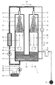
- the conditioning device designated 1 in FIG. 1 serves to condition both a combustion gas 2, e.g. Combustion air or fuel gas, as well as an exhaust gas 3 a heater or internal combustion engine (Not shown).
- a combustion gas 2 e.g. Combustion air or fuel gas
- an exhaust gas 3 e.g. Combustion air or fuel gas
- the conditioning device 1 has two rooms 4, 7 in Form of vertical hollow profiles (tubes) with round or polygonal cross section.
- first room 4 that is Combustion gas 2 in and through an upper inlet 5 diverted a lower outlet 6 located lower.
- the exhaust gas 3 is via a lower one Inlet 8 in and over a higher upper outlet 9th re-routed.
- the flow directions of combustion gas 2 and exhaust gas 3 in the two rooms 4, 7 are through Flow arrows indicated.
- the two rooms 4, 7 are over a connection 10 communicating with each other, wherein they are completed down by a common floor 11 are.
- each room 4, 7 is above the higher one Inlet 5 or outlet 9, a spray device 12 or 13 provided over which a liquid 14, 15 over a large area is sprayed down or injected.
- This sprayed Liquid 14, 15 collects below in a liquid "sump" 16.
- the one in rooms 4, 7 Liquid is condensate from the combustion process, which is constantly caused by water from the combustion the hydrocarbons are enriched and renewed.
- the combustion gas 2 is in cocurrent and the exhaust gas 3 in counterflow with respect to the spray direction the liquid 14, 15 passed through the rooms 4, 7.
- the liquid sump 16 is connected via a circuit line 17 liquid is removed in the direction of arrow 19 by means of a pump 18 and the spray devices 12, 13 fed so that there is a closed liquid cycle.
- the sensible heat contained in the exhaust gas 3 goes to the sprayed colder liquid 15 over.
- the exhaust gas 3 is cooled and warmed the sprayed liquid 15.
- the in Exhaust gas 3 contains latent heat, i.e. the heat of vaporization of the water vapor carried in the exhaust gas 3 goes to the sprayed Liquid 15 over.
- the exhaust gas 3 can do more Give off heat, the sprayed liquid 15 more warm take up.
- the water vapor contained in the exhaust gas 3 liquefies yourself.
- the exhaust gas 3 is dehumidified and the sprayed Liquid 15 enriched with water. Contained in the exhaust gas 3 Particles are caused by the sprayed-in liquid 15 washed out. Overall, the exhaust gas 3 leaves the second Room 7 cooled, dehumidified and cleaned.
- Rooms 4, 7 are connected to one above connection 10 provided overflow line 23 equipped via the maximum liquid level 24 or the filling of the rooms 4, 7 limited and excess liquid in a sewer 25 is dissipated. So that no too acidic liquid is discharged, there is a neutralization device in the circuit line 17 26 provided in which the liquid is neutralized accordingly.
- the one enriched with particles Liquid can also be used to emulsify the water Fuel oil for e.g. a diesel engine can be used.
- the liquid delivered in the circuit line 17 is additionally via a line 27 and by means of a pump 28 conductive via a heat exchanger 29 with which the liquid Deprived of heat and e.g. are released to the outside air 30 can.
- FIGs. 2 and 3 is an embodiment of an egg according to the invention Conditioning device 101 shown, both of which communicatively interconnected via connection 110 Rooms 104, 107 from each other by a common partition 131 are separated.
- the two rooms 104, 107 are still through two partitions 132, 133 and a continuous one Intermediate wall 134 like a chessboard in four vertical Subspaces 104a-104d and 107a-107d divided.
- the flow of combustion gas described below 102 and exhaust 103 through the conditioning device 101 is in the fig. 2 and 3 illustrated by flow arrows.
- the combustion gas 102 flows through a lower inlet 105 into the first sub-space 104a, flows upwards in it, until it has an upper connection opening in the partition 132 reaches the second subspace 104b. In this it flows down and passes through a lower connection opening in the intermediate wall 134 into the third sub-space 104c one it flows through up until it finally over an upper connection opening in the intermediate wall 132 in FIGS flows into fourth sub-space 104d. Via the lower outlet 106 occurs the combustion gas flowing down in the fourth sub-space 104d 102 out.
- the exhaust gas 103 flows into the through a lower inlet 108 a first subspace 107a, flows upward in this until it via an upper connection opening in the intermediate wall 133 enters the second subspace 107b. It flows in this down and enters through a lower connection opening the partition 134 into the third subspace 107c, the it flows upwards until it finally reaches an upper one Connection opening in the partition 133 in the fourth Partial space 107d flows. Steps over the lower outlet 109 the exhaust gas 103 which has flowed downward in the fourth subspace 107d out.
- the vertical subspaces 104a-104d and 107a-107d respectively thus successively from the combustion gas 102 or from the exhaust gas 103 and flows in a serpentine shape.
- the combustion gas 102 and exhaust 103 may e.g. in the second and third subspaces 104b, 104c and 107b, 107c in direct current and then sprayed with liquid in countercurrent from above and finally e.g. in the last compartment 104d or 107d are subjected to droplet separation before them via the outlet 106 or 109 from the conditioning device 101 exit.
Landscapes
- Engineering & Computer Science (AREA)
- Chemical & Material Sciences (AREA)
- Environmental & Geological Engineering (AREA)
- Health & Medical Sciences (AREA)
- Biomedical Technology (AREA)
- Analytical Chemistry (AREA)
- General Chemical & Material Sciences (AREA)
- Oil, Petroleum & Natural Gas (AREA)
- Chemical Kinetics & Catalysis (AREA)
- General Engineering & Computer Science (AREA)
- Mechanical Engineering (AREA)
- Treating Waste Gases (AREA)
- Incineration Of Waste (AREA)
- Regulation And Control Of Combustion (AREA)
Claims (17)
- Procédé pour le conditionnement d'un gaz de combustion (2 ; 102), en particulier d'air de combustion, et d'un gaz d'échappement (3 ; 103), que l'on amène à, et respectivement que l'on évacue depuis, un dispositif de chauffage ou un moteur à combustion interne, dans lequel le gaz de combustion (2 ; 102) est passé à travers une première chambre (4 ; 104) et le gaz d'échappement (3 ; 103) est passé à travers une deuxième chambre (7 ; 107) qui communique avec la première chambre (4 ; 104), et cela respectivement au-dessus de la jonction (10 ; 110) des deux chambres (4, 7 ; 104, 107), et sont alors pulvérisés avec un liquide (14, 15) qui et se trouve en bas dans les chambres (4, 7 ; 104, 107) et dont le niveau de liquide (24) est maintenu à un niveau plus élevé que la jonction (10 ; 110),
caractérisé en ce que le gaz de combustion (102) et/ou le gaz d'échappement (103) traverse(nt) respectivement plusieurs chambres partielles (104a-104d ; 107a-107d) de la première ou de la deuxième chambre (104, 107) approximativement verticalement les unes après les autres, et les directions d'écoulement dans les chambres partielles (104a-104d ; 107a-107d) d'une chambre (104, 107) traversées les unes après les autres sont respectivement opposées les unes aux autres. - Procédé de conditionnement selon la revendication 1, caractérisé en ce que le gaz de combustion (2 ; 102) et/ou le gaz d'échappement (3 ; 103) est/sont mené(s) à travers la chambre respective (4, 7 ; 104, 107) à contre-courant par rapport à la direction de pulvérisation du liquide (14, 15).
- Procédé de conditionnement selon l'une ou l'autre des revendications 1 et 2, caractérisé en ce que le liquide qui se trouve dans les chambres (4, 7 ; 104, 107) est prélevé au voisinage de sa surface (24).
- Procédé de conditionnement selon l'une des revendications précédentes, caractérisé en ce que le liquide qui se trouve dans les chambres (4, 7 ; 104, 107) est maintenu en mouvement.
- Procédé de conditionnement selon l'une des revendications précédentes, caractérisé en ce que le liquide est neutralisé.
- Procédé de conditionnement selon l'une des revendications précédentes, caractérisé en ce que le liquide peut être refroidi à l'extérieur.
- Appareil (1 ; 101) pour le conditionnement d'un gaz de combustion (2 ; 102), en particulier d'air de combustion, et d'un gaz d'échappement (3 ; 103), que l'on amène à, et respectivement que l'on évacue depuis, un dispositif de chauffage ou un moteur à combustion interne, pour la mise en oeuvre du procédé de conditionnement selon l'une des revendications précédentes, comprenant deux chambres (4, 7 ; 104, 107) communiquant l'une avec l'autre via une jonction (10 ; 110), dans lequel le gaz de combustion (2 ; 102) est passé à travers une (première) chambre (4 ; 104) et le gaz d'échappement (3 ; 103) est passé à travers l'autre (deuxième) chambre (7 ; 107) respectivement au-dessus de la jonction (10 ; 110) et sont alors pulvérisés au moyen d'un dispositif de pulvérisation (12, 13) avec un liquide (14, 15) qui se trouve en bas dans les chambres (4, 7 ; 104, 107), dont le niveau de liquide (24) est maintenu à un niveau plus élevé que la jonction (10 ; 110), caractérisé en ce que les deux chambres (4,7 ; 104, 107) comprennent un fond commun (11), et en ce que l'une ou les deux chambres (104 ; 107) est(sont) subdivisées en plusieurs chambres partielles (104a-104d ; 107a-107d) qui s'étendent approximativement verticalement, et qui sont traversées par le gaz de combustion (102), ou respectivement par le gaz d'échappement (103), les unes après les autres, et en particulier suivant un parcours en méandres.
- Appareil de conditionnement selon la revendication 7, caractérisé en ce que dans la deuxième chambre (7 ; 107) pour le gaz d'échappement (3 ; 103) l'entrée (8 ; 108) est agencée au-dessous de la sortie (9).
- Appareil de conditionnement selon l'une ou l'autre des revendications 7 et 8, caractérisé en ce que le dispositif de pulvérisation (12, 13) est agencé dans la chambre respective (4, 7 ; 104, 107) au-dessus de l'entrée ou de la sortie (5, 6 ; 7, 8 ; 106 ; 108), pour le gaz de combustion (2) ou respectivement pour le gaz d'échappement (3 ; 103), qui est située respectivement le plus en haut.
- Appareil de conditionnement selon l'une des revendications 7 à 9, caractérisé par une conduite de trop-plein (23), prévue dans l'une au moins des chambres (4, 7 ; 104, 107) et qui est située entre la jonction (10 ; 110) et l'entrée ou la sortie (5, 6 ; 7, 8 ; 106 ; 108), pour le gaz de combustion (2 ; 102) ou respectivement pour le gaz d'échappement (3 ; 103), qui est située respectivement le plus en bas.
- Appareil de conditionnement selon l'une des revendications 7 à 10, caractérisé par une conduite de recirculation (17) au moyen de laquelle le liquide qui se trouve dans les chambres (4, 7 ; 104, 107), de préférence en bas, est amené au dispositif de pulvérisation respectif (12, 13).
- Appareil de conditionnement selon l'une des revendications 7 à 11, caractérisé par un dispositif de neutralisation (26) qui neutralise le liquide.
- Appareil de conditionnement selon l'une des revendications 7 à 12, caractérisé par un dispositif de mise en mouvement qui maintient en mouvement le liquide qui se trouve dans les chambres (4, 7 ; 104, 107).
- Appareil de conditionnement selon la revendication 13, caractérisé en ce que l'on prévoit à titre de dispositif de mise en mouvement une conduite de circulation (20) qui débouche dans l'une ou dans les deux chambres (4, 7 ; 104, 107), via laquelle le liquide prélevé de la ou des chambres (4, 7 ; 104, 107) est à nouveau ramené aux chambres (4, 7 ; 104, 107), de préférence en circuit fermé.
- Appareil de conditionnement selon l'une des revendications 7 à 14, caractérisé par un échangeur de chaleur (29), à travers lequel peut être passé le liquide.
- Appareil de conditionnement selon l'une des revendications 7 à 15, caractérisé en ce que les deux chambres (104, 107) sont séparées l'une de l'autre par une paroi de séparation commune (131).
- Appareil de conditionnement selon l'une des revendications 7 à 16, caractérisé en ce que les plusieurs chambres partielles (104a-104d ; 107a-107d) sont agencées les unes à côté des autres à la manière d'un damier.
Applications Claiming Priority (2)
| Application Number | Priority Date | Filing Date | Title |
|---|---|---|---|
| DE19746129 | 1997-10-18 | ||
| DE19746129A DE19746129C1 (de) | 1997-10-18 | 1997-10-18 | Verfahren und Vorrichtung zur Konditionierung eines Verbrennungsgases und eines Abgases |
Publications (3)
| Publication Number | Publication Date |
|---|---|
| EP0909578A2 EP0909578A2 (fr) | 1999-04-21 |
| EP0909578A3 EP0909578A3 (fr) | 1999-11-24 |
| EP0909578B1 true EP0909578B1 (fr) | 2001-03-21 |
Family
ID=7845961
Family Applications (1)
| Application Number | Title | Priority Date | Filing Date |
|---|---|---|---|
| EP98119082A Expired - Lifetime EP0909578B1 (fr) | 1997-10-18 | 1998-10-09 | Procédé et dispositif pour conditionner un gaz à brûler et un gaz d'échappement |
Country Status (3)
| Country | Link |
|---|---|
| EP (1) | EP0909578B1 (fr) |
| AT (1) | ATE199839T1 (fr) |
| DE (2) | DE19746129C1 (fr) |
Families Citing this family (2)
| Publication number | Priority date | Publication date | Assignee | Title |
|---|---|---|---|---|
| ITMO20030149A1 (it) * | 2003-05-22 | 2004-11-23 | Sola Enzo E C Snc | Sistema filtrante. |
| WO2012100157A1 (fr) * | 2011-01-20 | 2012-07-26 | Saudi Arabian Oil Company | Procédé direct de densification et système utilisant la chaleur résiduelle pour récupération à bord et stockage de co2 à partir des gaz d'échappement de moteur à combustion interne de véhicule motorisé |
Family Cites Families (5)
| Publication number | Priority date | Publication date | Assignee | Title |
|---|---|---|---|---|
| US3386798A (en) * | 1964-11-30 | 1968-06-04 | American Standard Inc | Method of removing sulfur compounds and precovering heat from combustion gases |
| FR2605720B3 (fr) * | 1986-10-22 | 1989-02-03 | Seccacier | Chaudiere a condensation |
| DD272416A1 (de) * | 1988-06-10 | 1989-10-11 | Inst Forsch Ration Zuckerind | Verfahren zur rueckgewinnung der waerme von rauchgasen |
| FR2636129B1 (fr) * | 1988-09-06 | 1991-05-17 | Gaz De France | Generateur de chaleur pour chauffage de fluide a haute temperature procedant par contact direct |
| FR2703136B1 (fr) * | 1993-03-25 | 1995-06-16 | Gaz De France | Procede de traitement des gaz chauds et pollues issus d'un reacteur thermique incluant une combustion. |
-
1997
- 1997-10-18 DE DE19746129A patent/DE19746129C1/de not_active Expired - Fee Related
-
1998
- 1998-10-09 AT AT98119082T patent/ATE199839T1/de not_active IP Right Cessation
- 1998-10-09 DE DE59800554T patent/DE59800554D1/de not_active Expired - Fee Related
- 1998-10-09 EP EP98119082A patent/EP0909578B1/fr not_active Expired - Lifetime
Also Published As
| Publication number | Publication date |
|---|---|
| ATE199839T1 (de) | 2001-04-15 |
| EP0909578A3 (fr) | 1999-11-24 |
| DE59800554D1 (de) | 2001-04-26 |
| DE19746129C1 (de) | 1999-01-14 |
| EP0909578A2 (fr) | 1999-04-21 |
Similar Documents
| Publication | Publication Date | Title |
|---|---|---|
| DE19629500C1 (de) | Multiwäscher und Verfahren zur Totalreinigung von Gasen | |
| DE2907310A1 (de) | Farbspritzkabine | |
| DE3706072A1 (de) | Luftgekuehlte absorptionsheiz- und -kuehlanlage | |
| WO1984003843A1 (fr) | Installation pour le traitement des gaz de combustion | |
| EP0160161A1 (fr) | Echangeur de chaleur pour refroidir des gaz | |
| DE3106716C2 (fr) | ||
| DE102004005689A1 (de) | Ausdampfverfahren zur Reinigung und/oder Aufkonzentrierung verunreinigter Flüssigkeiten | |
| DE2512233A1 (de) | Verfahren und vorrichtung zur waermerueckgewinnung aus rauchgasen | |
| DE19533987C2 (de) | Verfahren zur Rückgewinnung von Wärme aus den Abgasen von Feuerungsanlagen | |
| EP0909578B1 (fr) | Procédé et dispositif pour conditionner un gaz à brûler et un gaz d'échappement | |
| EP3523587B1 (fr) | Système de réfrigération | |
| WO1985002129A1 (fr) | Procede et installation pour rechauffer les gaz purifies suite a la purification par voie humide de gaz bruts | |
| DE69829870T2 (de) | Vorrichtung zur kühlung von gasen | |
| DE2538168B2 (de) | Wärmetauscher zur Aufheizung von Kaltwasser | |
| AT405376B (de) | Verfahren zur kühlung von schadstoffbeladenem heissem rohgas und anordnung zur durchführung des verfahrens | |
| DE1812439A1 (de) | Verfahren und Vorrichtung fuer den Waermeaustausch zwischen zwei Gasen | |
| DE3223714A1 (de) | Vorrichtung zur gasbehandlung | |
| DE444017C (de) | Schnelldampferzeuger mit aus durchgehenden Windungen bestehenden Schraubenroehren | |
| EP0864816B1 (fr) | Procédure et installation pour la récupération de la chaleur résiduelle dans les fumées d'un foyer | |
| DE8810151U1 (de) | Wärmeaustauscher für wahlweisen Naß- und Trockenbetrieb | |
| DE2219083C3 (de) | Absorptionskälteanlage | |
| DE2906394C2 (de) | Luftgekühlte Kondensatoren | |
| DE3516054A1 (de) | Verfahren und anlage zur reinigung von rauchgasen | |
| DE29709784U1 (de) | Einrichtung zur Energierückgewinnung | |
| DE2535713C3 (de) | Heizungskessel für strömende Brennstoffe |
Legal Events
| Date | Code | Title | Description |
|---|---|---|---|
| PUAI | Public reference made under article 153(3) epc to a published international application that has entered the european phase |
Free format text: ORIGINAL CODE: 0009012 |
|
| AK | Designated contracting states |
Kind code of ref document: A2 Designated state(s): AT CH DE LI |
|
| AX | Request for extension of the european patent |
Free format text: AL;LT;LV;MK;RO;SI |
|
| PUAL | Search report despatched |
Free format text: ORIGINAL CODE: 0009013 |
|
| AK | Designated contracting states |
Kind code of ref document: A3 Designated state(s): AT BE CH CY DE DK ES FI FR GB GR IE IT LI LU MC NL PT SE |
|
| AX | Request for extension of the european patent |
Free format text: AL;LT;LV;MK;RO;SI |
|
| RIC1 | Information provided on ipc code assigned before grant |
Free format text: 6B 01D 53/79 A, 6F 23J 15/00 B, 6F 23L 15/04 B, 6F 02G 5/00 B, 6F 23J 15/04 B, 6F 24H 8/00 B |
|
| 17P | Request for examination filed |
Effective date: 19991222 |
|
| 17Q | First examination report despatched |
Effective date: 20000320 |
|
| GRAG | Despatch of communication of intention to grant |
Free format text: ORIGINAL CODE: EPIDOS AGRA |
|
| AKX | Designation fees paid |
Free format text: AT CH DE LI |
|
| GRAG | Despatch of communication of intention to grant |
Free format text: ORIGINAL CODE: EPIDOS AGRA |
|
| GRAH | Despatch of communication of intention to grant a patent |
Free format text: ORIGINAL CODE: EPIDOS IGRA |
|
| GRAH | Despatch of communication of intention to grant a patent |
Free format text: ORIGINAL CODE: EPIDOS IGRA |
|
| GRAA | (expected) grant |
Free format text: ORIGINAL CODE: 0009210 |
|
| AK | Designated contracting states |
Kind code of ref document: B1 Designated state(s): AT CH DE LI |
|
| REF | Corresponds to: |
Ref document number: 199839 Country of ref document: AT Date of ref document: 20010415 Kind code of ref document: T |
|
| REG | Reference to a national code |
Ref country code: CH Ref legal event code: EP |
|
| REF | Corresponds to: |
Ref document number: 59800554 Country of ref document: DE Date of ref document: 20010426 |
|
| REG | Reference to a national code |
Ref country code: CH Ref legal event code: NV Representative=s name: TROESCH SCHEIDEGGER WERNER AG |
|
| EN | Fr: translation not filed | ||
| PGFP | Annual fee paid to national office [announced via postgrant information from national office to epo] |
Ref country code: DE Payment date: 20011027 Year of fee payment: 4 |
|
| PGFP | Annual fee paid to national office [announced via postgrant information from national office to epo] |
Ref country code: AT Payment date: 20011030 Year of fee payment: 4 |
|
| PLBE | No opposition filed within time limit |
Free format text: ORIGINAL CODE: 0009261 |
|
| STAA | Information on the status of an ep patent application or granted ep patent |
Free format text: STATUS: NO OPPOSITION FILED WITHIN TIME LIMIT |
|
| 26N | No opposition filed | ||
| PG25 | Lapsed in a contracting state [announced via postgrant information from national office to epo] |
Ref country code: AT Free format text: LAPSE BECAUSE OF NON-PAYMENT OF DUE FEES Effective date: 20021009 |
|
| PG25 | Lapsed in a contracting state [announced via postgrant information from national office to epo] |
Ref country code: LI Free format text: LAPSE BECAUSE OF NON-PAYMENT OF DUE FEES Effective date: 20021031 Ref country code: CH Free format text: LAPSE BECAUSE OF NON-PAYMENT OF DUE FEES Effective date: 20021031 |
|
| PG25 | Lapsed in a contracting state [announced via postgrant information from national office to epo] |
Ref country code: DE Free format text: LAPSE BECAUSE OF NON-PAYMENT OF DUE FEES Effective date: 20030501 |
|
| REG | Reference to a national code |
Ref country code: CH Ref legal event code: PL |