EP0909631A2 - Doppelfolien Wärmformvorrichtung - Google Patents
Doppelfolien Wärmformvorrichtung Download PDFInfo
- Publication number
- EP0909631A2 EP0909631A2 EP98114679A EP98114679A EP0909631A2 EP 0909631 A2 EP0909631 A2 EP 0909631A2 EP 98114679 A EP98114679 A EP 98114679A EP 98114679 A EP98114679 A EP 98114679A EP 0909631 A2 EP0909631 A2 EP 0909631A2
- Authority
- EP
- European Patent Office
- Prior art keywords
- platen
- lower platen
- positions
- range
- locking shafts
- Prior art date
- Legal status (The legal status is an assumption and is not a legal conclusion. Google has not performed a legal analysis and makes no representation as to the accuracy of the status listed.)
- Withdrawn
Links
Images

Classifications
-
- B—PERFORMING OPERATIONS; TRANSPORTING
- B29—WORKING OF PLASTICS; WORKING OF SUBSTANCES IN A PLASTIC STATE IN GENERAL
- B29C—SHAPING OR JOINING OF PLASTICS; SHAPING OF MATERIAL IN A PLASTIC STATE, NOT OTHERWISE PROVIDED FOR; AFTER-TREATMENT OF THE SHAPED PRODUCTS, e.g. REPAIRING
- B29C51/00—Shaping by thermoforming, i.e. shaping sheets or sheet like preforms after heating, e.g. shaping sheets in matched moulds or by deep-drawing; Apparatus therefor
- B29C51/26—Component parts, details or accessories; Auxiliary operations
- B29C51/266—Auxiliary operations after the thermoforming operation
- B29C51/267—Two sheets being thermoformed in separate mould parts and joined together while still in the mould
-
- B—PERFORMING OPERATIONS; TRANSPORTING
- B29—WORKING OF PLASTICS; WORKING OF SUBSTANCES IN A PLASTIC STATE IN GENERAL
- B29C—SHAPING OR JOINING OF PLASTICS; SHAPING OF MATERIAL IN A PLASTIC STATE, NOT OTHERWISE PROVIDED FOR; AFTER-TREATMENT OF THE SHAPED PRODUCTS, e.g. REPAIRING
- B29C51/00—Shaping by thermoforming, i.e. shaping sheets or sheet like preforms after heating, e.g. shaping sheets in matched moulds or by deep-drawing; Apparatus therefor
- B29C51/26—Component parts, details or accessories; Auxiliary operations
- B29C51/30—Moulds
- B29C51/38—Opening, closing or clamping means
-
- B—PERFORMING OPERATIONS; TRANSPORTING
- B29—WORKING OF PLASTICS; WORKING OF SUBSTANCES IN A PLASTIC STATE IN GENERAL
- B29C—SHAPING OR JOINING OF PLASTICS; SHAPING OF MATERIAL IN A PLASTIC STATE, NOT OTHERWISE PROVIDED FOR; AFTER-TREATMENT OF THE SHAPED PRODUCTS, e.g. REPAIRING
- B29C51/00—Shaping by thermoforming, i.e. shaping sheets or sheet like preforms after heating, e.g. shaping sheets in matched moulds or by deep-drawing; Apparatus therefor
- B29C51/26—Component parts, details or accessories; Auxiliary operations
- B29C51/46—Measuring, controlling or regulating
Definitions
- thermoforming apparatus and more particularly apparatus for forming two preheated sheets of plastic into separate part halves in separate upper and lower molds, the part halves subsequently having their edges sealed together by pressing the upper and lower molds together to form a single unitary part.
- twin sheet thermoforming apparatus and methods have heretofore been developed to produce such parts as automotive fuel tanks, etc.
- the upper and lower molds are installed in respective upper and lower platens which are driven apart to separate the molds sufficiently to allow unloading the completed parts.
- the means for forcing one mold against the other to fuse the part seam has involved the use of a series of inflatable tubes or bags disposed beneath the lower mold.
- the inflatable tubes or bags are inflated, lifting the lower mold to be pressed against the upper mold causing the part half perimeters to be fused together.
- inflatable bags or tubes is effective to apply a fusing pressure but results in an imperfect uniformity of the seam and the final size of the part, since the extent of squeezing may not be completely uniform as there is no positive control over the movement of the mold.
- twin sheet thermoforming apparatus have sets of platen locking shafts carried by the upper and lower platens, which shafts are coupled together when the mold parts are squeezed together. These shafts have each been threaded to a nut component which controls the relative position of the mold parts when the platens are locked together at the initiation of the squeeze cycle, thus predetermining the final seam thickness and part size after the maximum travel of the cylinders has been reached.
- the fluid flow to each cylinder is controlled by routing the hydraulic fluid through a flow divider such that uniform travel of each cylinder piston is insured during the squeezing process, resulting in a uniform depth seam being formed.
- the locking shafts on the upper platen are threaded and each are received in a rotatable nut component having a chain sprocket fixedly attached.
- a driven recirculating chain engages each sprocket nut such that simultaneous rotation of all of the sprocket nuts occurs to precisely execute a uniform simultaneous adjustment of all of the locking shafts on the upper platen. This enables a rapid yet precise adjustment of the relative position of the platens when they are locked together for a given part application.
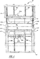
- thermoformer apparatus 10 according to the present invention is shown without certain conventional portions thereof, such as the heating oven, part handling mechanisms, etc. in the interests of clarity, as they do not form a part of the present invention and are well known to those skilled in the art.
- the apparatus 10 includes an upper platen 12 and a lower platen 14 each drivably movable up and down within a machine frame, portions 16 shown in Figure 1.
- the upper and lower platens 12, 14 are each supported on respective sets of four gear rack support posts 18A, 18B, the platens 12, 14 adapted to be driven up and down on the posts 18A, 18B, respectively, to thereby be positioned closer or further apart.
- a drive system for this purpose comprises platen positioning means which includes respective electric drive motors 20A, 20B each driving sets of cross shafts 22A, 22B and 24A, 24B via drive belts 26 and pulleys 28.
- the cross shafts 22A, 22B, 24A, 24B each have a pinion gear 30 at each end engaging a respective one of the gear racks machined into the vertical support posts 18A, 18B.
- a conventional servo control system is used to control the motors 20A, 20B to drive the upper and lower platens 12, 14 to a predetermined location.
- a disc brake 32A, 32B is used to hold the platens 12, 14 in a selected vertical position on the posts 18A, 18B.
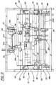
- the sides of the upper platen 12 carry a first set of vertically extending locking shafts, comprised of pairs of threaded locking shafts 34A, 34B on sets of plates 36 welded to each side of the upper platen 12, reinforcing gussets 38 and shaft guide plates 40 also provided welded to the side of the upper platen 12 ( Figure 6).
- Each of the threaded locking shafts 34A, 34B are threadably engaged by being received in nut members 42 disposed over a respective plate 36 and resting on a rotary bearing 44 ( Figure 6).
- Hold-down rollers 46 engage a flange 48 so as to prevent the nut members 42 from advancing upwardly on threaded shaft 34A or 34B when rotated.
- the four nut members 42 are able to all be simultaneously rotated by means of a recirculating chain 50 engaging a sprocket 52 fixed to each nut member 42. Suitable idler guide sprockets are provided as shown.
- the chain 50 is driven by an electric motor 54 and right angle drive 56 rotating a drive sprocket 58 engaging the chain 50.
- a bar 60 is fixed across the tops of each pair of threaded locking shafts 34A, 34B to prevent their rotation. Thus, the shafts 34A, 34B are simultaneously rotated when the chain 50 is driven.
- each locking shaft 34A, 34B carries a fluid pressure operated coupling mechanism 62 of a well known commercially available type, such as from Locking Cylinder Technologies, Inc. of Racine, Wisconsin.
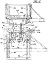
- the coupling mechanisms 62 are each aligned with a respective one of a second set of vertical locking shafts, comprised of pairs of hydraulic cylinder shafts 64 projecting upwardly from each side of the lower platen 14.
- the shafts 64 each have a locking bolt 66 secured to its end adapted to be selectively locked in the aligned coupling mechanism 62 when mechanisms 62 are activated.
- the cylinder shafts 64 project upwardly from an associated short stroke hydraulic cylinder 68 secured to a plate 70 welded to a pair of gussets 72, in turn welded to a side of the lower platen 14.
- the cylinder shafts 64 are each guided by passing through a bushing in an upwardly spaced plate 74 as shown.
- the hydraulic cylinders 68 are of a short stroke high force type, with large forces generated to produce the squeezing of the part rim (not shown).
- the cylinders 68 preferably are stroked against a fixed stop, as by bottoming of the piston 69 ( Figure 4) against the cylinder endwalls to be positively located when the upper platen 12 and lower platen 14 are fully drawn together. This insures an accurately sized part.
- a position encoder 76 generates a control signal corresponding to the travel of the shafts 64.
- the flow divider 78 is a commercially available device (Delta HPR 23-59) resembling a multiple rotor, positive displacement gear motor. Hydraulic fluid to one of the cylinders 68 is routed through one of the rotors R 1 causing it to be rotated. The remaining rotors R 2 -R 4 are connected to be rotated in unison therewith. The hydraulic fluid is gated via these other rotors R 2 -R 4 to the other three cylinders 64. This establishes uniform flow to and thus displacement of each cylinder 68.
- the upper and lower platens are driven to be located properly by motors 20A, 20B to allow heated sheets to be introduced between the molds M U , M L .
- a conventional thermoforming process is carried out in each mold M U , M L to form each part half with a flange extending over the outer perimeter of the respective mold faces, in the well known manner.
- the cylinders 68 are pressurized so as to cause the cylinder shafts 64 to be pulled down to draw the molds M U , M L together, squeezing the part rims together, forming a part seam of a uniform thickness when the cylinders are fully stroked, this stroking proceeding uniformly due to the action of the flow divider 78.
- the upper platen 12 is held by the brakes 32A while the brakes 32 associated with the lower platen 14 are released.
- the motor 20B is driven by application of the signal from the rotary encoder 76 to the motor servo control 80 so as to cause the lower platen 14 to be driven by the motor 20B to cause the lower platen 14 to "follow" the upward movement of the lower platen 14 caused by the action of the hydraulic cylinders 64.
- the weight of the lower platen 14 is supported by the motor 20B to avoid being added to the weight supported by the brakes holding the upper platen 12.
- the platens 12, 14 are thereafter released through deactivation of the coupling mechanisms 62 and release of the brakes 32A to be able to be driven apart and allow the completed part (not shown) to be removed.
- a manual operation of the chain drive is possible, as is an automatic programmed powered drive of the chain 50 and nut members 42.
- an improved apparatus allowing more accurately sized parts to be produced and allowing rapid and accurate changeover of tooling for parts of different configurations.
Landscapes
- Engineering & Computer Science (AREA)
- Mechanical Engineering (AREA)
- Blow-Moulding Or Thermoforming Of Plastics Or The Like (AREA)
- Moulds For Moulding Plastics Or The Like (AREA)
Applications Claiming Priority (2)
| Application Number | Priority Date | Filing Date | Title |
|---|---|---|---|
| US08/941,826 US5814185A (en) | 1997-10-01 | 1997-10-01 | Twin sheet thermoformer |
| US941826 | 1997-10-01 |
Publications (2)
| Publication Number | Publication Date |
|---|---|
| EP0909631A2 true EP0909631A2 (de) | 1999-04-21 |
| EP0909631A3 EP0909631A3 (de) | 1999-07-28 |
Family
ID=25477132
Family Applications (1)
| Application Number | Title | Priority Date | Filing Date |
|---|---|---|---|
| EP98114679A Withdrawn EP0909631A3 (de) | 1997-10-01 | 1998-08-04 | Doppelfolien Wärmformvorrichtung |
Country Status (2)
| Country | Link |
|---|---|
| US (1) | US5814185A (de) |
| EP (1) | EP0909631A3 (de) |
Cited By (1)
| Publication number | Priority date | Publication date | Assignee | Title |
|---|---|---|---|---|
| CN103261703A (zh) * | 2010-12-10 | 2013-08-21 | 丰田自动车株式会社 | 离心压缩机 |
Families Citing this family (23)
| Publication number | Priority date | Publication date | Assignee | Title |
|---|---|---|---|---|
| US5972150A (en) * | 1998-04-20 | 1999-10-26 | Copp; John B. | Lamination stabilizer block |
| US6294114B1 (en) | 1998-08-20 | 2001-09-25 | Scott A. W. Muirhead | Triple sheet thermoforming apparatus, methods and articles |
| US6749418B2 (en) | 1998-08-20 | 2004-06-15 | Scott A. W. Muirhead | Triple sheet thermoforming apparatus |
| US6372176B1 (en) | 1999-03-01 | 2002-04-16 | Kiefel Technologies Inc. | System and method for twin sheet forming |
| US6200122B1 (en) * | 1999-08-03 | 2001-03-13 | Brown Machine, Llc. | Thermoforming apparatus with improved press |
| US8077040B2 (en) | 2000-01-24 | 2011-12-13 | Nextreme, Llc | RF-enabled pallet |
| US6661339B2 (en) | 2000-01-24 | 2003-12-09 | Nextreme, L.L.C. | High performance fuel tank |
| US7342496B2 (en) | 2000-01-24 | 2008-03-11 | Nextreme Llc | RF-enabled pallet |
| US6943678B2 (en) | 2000-01-24 | 2005-09-13 | Nextreme, L.L.C. | Thermoformed apparatus having a communications device |
| JP3394750B2 (ja) * | 2000-10-02 | 2003-04-07 | ファナック株式会社 | ワーク押し付け装置 |
| US6705853B1 (en) * | 2000-10-20 | 2004-03-16 | Durakon Industries, Inc. | Six station rotary thermoforming machine |
| US6969246B1 (en) | 2002-07-24 | 2005-11-29 | Brown Machine, Llc | Forming station and process for twin sheet thermoforming |
| US7045086B2 (en) * | 2003-03-13 | 2006-05-16 | Soroc Products, Inc. | Twinsheet thermoforming system and method |
| CN100488754C (zh) * | 2005-10-14 | 2009-05-20 | 鸿富锦精密工业(深圳)有限公司 | 热压成型机 |
| DE102006022634A1 (de) * | 2006-05-12 | 2007-11-15 | Uhlmann Pac-Systeme Gmbh & Co. Kg | Formstation |
| TWM332016U (en) * | 2007-11-12 | 2008-05-11 | Profile Tech Internat Co Ltd | Film thermoforming device |
| HRP20161668T1 (hr) | 2009-04-16 | 2017-02-24 | Andrew Niemczyk | Postupak za ubrizgavanje površinske vode u tlo |
| US8075816B2 (en) * | 2009-04-16 | 2011-12-13 | James Kundinger | Form station platen drive for a thermoforming machine and a method of leveling platens |
| US9649808B2 (en) | 2011-11-14 | 2017-05-16 | Irwin Research And Development, Inc. | Thermoforming machine having platen locks and method |
| US10502475B2 (en) | 2012-08-22 | 2019-12-10 | Carrier Corporation | Refrigerated container and duct extension |
| US10279507B2 (en) * | 2016-01-08 | 2019-05-07 | Columbia Machine, Inc. | Mold transfer assembly for concrete products forming machine |
| US20220297389A1 (en) * | 2021-03-16 | 2022-09-22 | Jack Reinke | Combined thermoforming and additive manufacturing device |
| CN113954337B (zh) * | 2021-10-29 | 2023-10-13 | 宁波喜悦智行科技股份有限公司 | 一种全自动吸塑一体机 |
Family Cites Families (6)
| Publication number | Priority date | Publication date | Assignee | Title |
|---|---|---|---|---|
| US3925140A (en) * | 1973-03-16 | 1975-12-09 | Koehring Co | Fabricating apparatus for twin-sheets |
| US4093498A (en) * | 1977-05-11 | 1978-06-06 | David Wendell | Automatic shirt collar stay applying machine |
| AU589749B2 (en) * | 1987-03-26 | 1989-10-19 | Tachi-S Co., Ltd. | Apparatus for manufacturing a seat |
| US5427732A (en) * | 1993-12-28 | 1995-06-27 | Shuert; Lyle H. | Method of forming deep draw twin sheet plastic articles |
| US5620715A (en) * | 1994-02-10 | 1997-04-15 | Penda Corporation | Thermoforming machine with controlled cooling station |
| US5658523A (en) * | 1995-06-06 | 1997-08-19 | Shuert; Lyle H. | Method and apparatus for forming twin sheet hollow plastic articles |
-
1997
- 1997-10-01 US US08/941,826 patent/US5814185A/en not_active Expired - Lifetime
-
1998
- 1998-08-04 EP EP98114679A patent/EP0909631A3/de not_active Withdrawn
Cited By (1)
| Publication number | Priority date | Publication date | Assignee | Title |
|---|---|---|---|---|
| CN103261703A (zh) * | 2010-12-10 | 2013-08-21 | 丰田自动车株式会社 | 离心压缩机 |
Also Published As
| Publication number | Publication date |
|---|---|
| US5814185A (en) | 1998-09-29 |
| EP0909631A3 (de) | 1999-07-28 |
Similar Documents
| Publication | Publication Date | Title |
|---|---|---|
| US5814185A (en) | Twin sheet thermoformer | |
| EP2650097B1 (de) | Vorrichtung und Verfahren zum Pressformen von Kunststoffgegenständen mit Fasern | |
| US4686129A (en) | Mold clamping mechanism for tire curing machines | |
| US4615669A (en) | Injection molding machine | |
| US4124242A (en) | Method and apparatus for loading presses | |
| US4950144A (en) | Nozzle touch apparatus in an injection molding machine | |
| CA2083046A1 (en) | Method and apparatus for mold clamping | |
| US5800846A (en) | Twin-sheet thermoforming apparatus with hydraulic array mold support | |
| DE69415263T2 (de) | Verfahren und Vorrichtung zur Schaumkunststoffherstellung | |
| US6638047B2 (en) | Molding machine | |
| US4743324A (en) | Printing plate mounter | |
| US6969246B1 (en) | Forming station and process for twin sheet thermoforming | |
| JPS63141716A (ja) | 精密コイニングの可能なトグル式プラスチック射出成形機用油圧システム | |
| CN117261289B (zh) | 一种用于井盖加工的成型液压机以及使用方法 | |
| CA1291857C (en) | Method and apparatus for forming disc wheel like formed parts | |
| JP2997137B2 (ja) | 竪型ロータリ式射出成形機 | |
| US5102327A (en) | Mold clamping system | |
| US5190714A (en) | Mold clamping system | |
| EP1364764A2 (de) | Rotationsformpresse mit Heizmitteln | |
| US3336636A (en) | Mounting mold sections used in vulcanizing presses | |
| US4749435A (en) | Apparatus for and method of producing resin laminated cards | |
| GB2101927A (en) | Moulding apparatus | |
| US3561063A (en) | Vertically oriented injection molding machine | |
| JP2001026039A (ja) | 射出成形機の金型交換装置および方法 | |
| CN221115978U (zh) | 一种热转印机的上下料结构 |
Legal Events
| Date | Code | Title | Description |
|---|---|---|---|
| PUAI | Public reference made under article 153(3) epc to a published international application that has entered the european phase |
Free format text: ORIGINAL CODE: 0009012 |
|
| AK | Designated contracting states |
Kind code of ref document: A2 Designated state(s): AT BE CH CY DE DK ES FI FR GB GR IE IT LI LU MC NL PT SE |
|
| AX | Request for extension of the european patent |
Free format text: AL;LT;LV;MK;RO;SI |
|
| PUAL | Search report despatched |
Free format text: ORIGINAL CODE: 0009013 |
|
| AK | Designated contracting states |
Kind code of ref document: A3 Designated state(s): AT BE CH CY DE DK ES FI FR GB GR IE IT LI LU MC NL PT SE |
|
| AX | Request for extension of the european patent |
Free format text: AL;LT;LV;MK;RO;SI |
|
| RAP1 | Party data changed (applicant data changed or rights of an application transferred) |
Owner name: BROWN MACHINE LLC |
|
| AKX | Designation fees paid | ||
| REG | Reference to a national code |
Ref country code: DE Ref legal event code: 8566 |
|
| STAA | Information on the status of an ep patent application or granted ep patent |
Free format text: STATUS: THE APPLICATION IS DEEMED TO BE WITHDRAWN |
|
| 18D | Application deemed to be withdrawn |
Effective date: 20000129 |