EP0909860B1 - Vorrichtung zum Aufbringen von Mörtel auf eine Seite von Steinen - Google Patents
Vorrichtung zum Aufbringen von Mörtel auf eine Seite von Steinen Download PDFInfo
- Publication number
- EP0909860B1 EP0909860B1 EP98114968A EP98114968A EP0909860B1 EP 0909860 B1 EP0909860 B1 EP 0909860B1 EP 98114968 A EP98114968 A EP 98114968A EP 98114968 A EP98114968 A EP 98114968A EP 0909860 B1 EP0909860 B1 EP 0909860B1
- Authority
- EP
- European Patent Office
- Prior art keywords
- arrangement
- thin
- mortar
- bricks
- bed mortar
- Prior art date
- Legal status (The legal status is an assumption and is not a legal conclusion. Google has not performed a legal analysis and makes no representation as to the accuracy of the status listed.)
- Expired - Lifetime
Links
Images


Classifications
-
- E—FIXED CONSTRUCTIONS
- E04—BUILDING
- E04G—SCAFFOLDING; FORMS; SHUTTERING; BUILDING IMPLEMENTS OR AIDS, OR THEIR USE; HANDLING BUILDING MATERIALS ON THE SITE; REPAIRING, BREAKING-UP OR OTHER WORK ON EXISTING BUILDINGS
- E04G21/00—Preparing, conveying, or working-up building materials or building elements in situ; Other devices or measures for constructional work
- E04G21/14—Conveying or assembling building elements
- E04G21/16—Tools or apparatus
- E04G21/20—Tools or apparatus for applying mortar
- E04G21/204—Mortar sledges
Definitions
- the invention relates to a device for applying Thin-bed mortar according to the preamble of claim 1.
- DE 196 12 900 A1 discloses a device for applying thin-bed mortar of controlled increased consistency for the creation of stone masonry with described large hole portion, wherein the modified thin-bed mortar means a continuous mixer and a pump under pressure over a Hose line is conveyed in an applicator.
- the applicator is a wide-spread nozzle
- the over a coupling on the input side is connected to the hose of the pump and whose width substantially corresponds to the brick width.
- the nozzle with means for lateral guidance on the stones and the Adjustment of the outlet end of the nozzle inclined working position is provided.
- EP 0 387 120 A1 relates to a device for applying mortar, which Having means for moving over a carrier, such as slides or wheels. there is in the box-shaped mortar application carriage according to this document Place a furrow in the mortar layer with a spatula in the middle.
- FR 2 742 181 A1 relates to a mortar applicator carriage whose outlet opening is trimmed so that the edges of the stones are not applied to mortar.
- the mortar applicator according to US 2,674,116 A is a box-shaped Cart that rolls on the stones to be acted on.
- These Mortar application device has laterally mounted guide rails, which to ensure a leadership of the device along a row of stones.
- Of the Mortar is discharged through recesses in the corners of the back wall, with the Size of the recesses is adjustable by means of flaps.
- the mortar carriage according to FR 1 096 113 A has a central installation, with which should be ensured that only strips of mortar on the edges of applied stones are applied.
- DE 297 01 834 U1 relates to a mortar carriage, with which large areas, such.
- plastic materials such as adhesive slurry or adhesive mortar, for subsequent laying of tiles or floor coverings can be applied.
- This mortar sled consists of one essentially at the top and bottom open cuboid box with a height-adjustable Rack on the back. Sideways skids as a deflector too already applied webs of adhesive slurry or adhesive mortar be attached but which are not suitable, a guide for applying a bearing joint to allow a stone row.
- the invention has the object of providing a mortar application carriage of the type mentioned in such a way that easily and easily masonry from baked and not necessarily post-processed, so plan ground, perforated bricks can be produced.
- a thin-bed mortar is to be used, with which it should be possible to reliably close the small chambers of perforated bricks and thus to produce a masonry with high quality.
- the present invention proposes a device for applying thin-bed mortar according to claim 1 in front. Further, advantageous embodiments are the subject of the dependent claims.
- the invention is based on the recognition that it is advantageous before the Stripping of the applied Thin-bed mortar with a rack as uniform as possible and intimate connection between the stone surface and the thin bed mortar manufacture. Therefore, it is provided that the thin-bed mortar over as large as possible Contact length - seen in the stripping direction of the thin-bed mortar - in contact with the stone is before it is scraped off the rack.
- an outwardly curved rack (7) is arranged in the region of the discharge opening (4) for thin bed mortar (2) in the region of the discharge opening (4) for thin bed mortar (2).
- the Bending the rack provides that a slight compression and thus a Comparative of the thin-bed mortar is done.
- the rack is laying down various applied mortar layer heights height adjustable.
- laterally Guide rails (8) are arranged.
- the lateral guide rails (8) with spring elements (9) on the Attached device (1) so that the guide rails (8) on the broad side of the Stones (3) rest under spring preload.
- the guide rails (8) in the direction of travel (s) of the device (1) are bent outwards.
- the device according to the invention may be made of stainless sheet metal or of plastic consist. For easy handling, it can have handles (11).
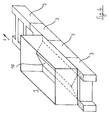
- a part of a wall of perforated bricks can be seen; three stones are 3 arranged next to each other and intended for recording the next stone layer to get prepared. For this purpose, a mortar layer on its upper surface applied.
- a mortar application slide 1 is used. It consists essentially of a cuboid box, the top of a filling opening 5 for Thin-bed mortar 2 has and below a discharge opening 4.
- the carriage 1 has a width substantially the width B of the stones 3 corresponds. Its length L and this width define the size of the filling opening 5.
- the carriage 1 is filled with thin-bed mortar 2 before use. Then he will be in the Moving direction s moves. Since the carriage is essentially a cuboid Shape has, the thin bed mortar 2 is also in the bottom portion of the carriage 1 substantially over the length L of the filling opening 5 on the stone surface. Ie. the Contact length of the thin-bed mortar 2 with the stone surface is largely equal to the Length L of the mortar application slide 1.
- a rack 7 ensures that the mortar layer applied to the stone surface has a desired height and a desired shape, as is good in the Fig. 1 can be seen.
- lateral Guide rails 8 present (in the example: on each side of a rail 8, the exact structure of the guide rails can be seen in Fig. 3).
- Fig. 3 shows a section along the line A-B (see Fig. 2) Clarity here the mortar sled 1 was less broad than the stone 3 shown having the width B. In fact, the widths of Sledge 1 and stone 3, however, largely. Good to see in this figure is that for lateral guidance of the slide 1 on both sides guide rails 8 available are. These are acted upon by springs 9 elastically, so that a prestressed Plant the guide rails 8 can be made to the side surfaces of the stones 3.
- guide rails 8 and Springs 9 holding frame 12 are provided to Creation of a stable composite of mortar carriages 1, guide rails 8 and Springs 9 holding frame 12 are provided. Not shown is that the guide rails 8 are bent in the direction of the carriage 1 to the outside, so that snagging of the rails can be excluded.
- Fig. 4 the case is shown that the masonry of stones 3 with very large, continuous hollow chambers to be manufactured. Consequently, the mortar layer should be applied only on the lateral edge regions of the stones 3.
- a cover insert 10 is provided, which has a roof-shaped shape in the example. Of the Insert causes the thin-bed mortar can penetrate only in the desired area.
- the lateral guide rail 8 (see Fig. 3) together with the holding frame 12 are in Fig. 4 of For clarity, not shown.
Landscapes
- Engineering & Computer Science (AREA)
- Architecture (AREA)
- Mechanical Engineering (AREA)
- Civil Engineering (AREA)
- Structural Engineering (AREA)
- Conveying And Assembling Of Building Elements In Situ (AREA)
- Finishing Walls (AREA)
Description
- Fig. 1
- zeigt in perspektivischer Ansicht den erfindungsgemäßen Mörtelauftragschlitten,
- Fig. 2
- stellt schematisch eine Seitenansicht des Schlittens dar, in
- Fig. 3
- ist ein Schnitt entlang der Linie A-B gemäß Fig. 2 zu sehen,
- Fig. 4
- stellt schließlich schematisch den Mörtelschlitten mit einem Abdeckeinsatz dar.
- 1
- Mörtelauftragschlitten
- 2
- Dünnbettmörtel
- 3
- Stein
- 4
- Austragsöffnung
- 5
- Einfüllöffnung
- 6
- Bodenbereich des Schlittens
- 7
- gebogene Zahnleiste
- 8
- seitliche Führungsschiene
- 9
- Federelement
- 10
- Abdeckeinsatz
- 11
- Handgriff
- 12
- Halterahmen
- s
- Verfahrrichtung des Schlittens 1
- B
- Breite der Steine 3
- L
- Länge der Einfüllöffnung 5
- LK
- Länge der Kontaktfläche zwischen Steinen 3 und, Dünnbettmörtel 2 im Bodenbereich 6 des Schlittens 1
Claims (7)
- Vorrichtung (1) zum Aufbringen von Dünnbettmörtel (2) auf eine Seite von Steinen (3), die zwecks Aufbringung des Dünnbettmörtels (2) über die Steine (3) in einer Verfahrrichtung (s) bewegbar ist, mit einem quaderförmigen Kasten, der eine untere Austragsöffnung (4) für den Dünnbettmörtel (2) und eine obere Einfüllöffnung (5) für den Dünnbettmörtel (2) aufweist, wobei die Einfüllöffnung (5) für den Dünnbettmörtel (2) eine Breite hat, die weitgehend der Breite (B) der Steine (3) entspricht, und eine Länge (L) hat, die im wesentlichen der Länge der Vorrichtung (1) entspricht, wobei in Gebrauchsstellung der Dünnbettmörtel (2) im Bodenbereich (6) der Vorrichtung (1) über eine Länge (LK) Kontakt mit der Oberfläche der Steine (3) hat, wobei die Länge (LK) im wesentlichen der Länge (L) der Einfüllöffnung (5) entspricht, wobei zur Führung der Vorrichtung (1) auf den Steinen (3) seitlich angeordnete Führungsschienen (8) angeordnet sind, die mit Federelementen (9) an der Vorrichtung (1) befestigt sind, so daß die Führungsschienen (8) an der Breitseite der Steine (3) unter Federvorspannung anliegen,
dadurch gekennzeichnet, daß im Bereich der Austragsöffnung (4) für den Dünnbettmörtel (2) eine höhenverstellbare, zum Vergleichmäßigen des Dünnbettmörtels (2) auswärts gebogene Zahnleiste (7) angeordnet ist und daß der Kontakt des Dünnbettmörtels (2) mit den Steinen (3) über ausgewählte Breitenbereiche der Vorrichtung (1) verhinderbar ist. - Vorrichtung nach Anspruch 1, dadurch gekennzeichnet, daß die Führungsschienen (8) in Verfahrrichtung (s) der Vorrichtung (1) nach außen gebogen sind, um ein Verhaken der Führungsschienen (8) beim Bewegen der Vorrichtung (1) zu verhindern.
- Vorrichtung nach Anspruch 1 oder 2, dadurch gekennzeichnet, daß die Verhinderung des Kontakts von Dünnbettmörtel (2) mit den Steinen (3) über ausgewählte Breitenbereiche der Vorrichtung (1) durch einen im Bodenbereich (6) der Vorrichtung (1) angeordneten Abdeckeinsatz (10) erfolgt.
- Vorrichtung nach Anspruch 3, dadurch gekennzeichnet, daß der Abdeckeinsatz (10) eine dachförmige Gestalt hat.
- Vorrichtung nach einem der Ansprüche 1 bis 4, dadurch gekennzeichnet, daß die Vorrichtung (1) aus nichtrostendem Blech besteht.
- Vorrichtung nach einem der Ansprüche 1 bis 4, dadurch gekennzeichnet, daß die Vorrichtung (1) aus Kunststoff besteht.
- Vorrichtung nach einem der Ansprüche 1 bis 6, dadurch gekennzeichnet, daß die Vorrichtung (1) Handgriffe (11) aufweist.
Applications Claiming Priority (2)
| Application Number | Priority Date | Filing Date | Title |
|---|---|---|---|
| DE19746181A DE19746181C2 (de) | 1997-10-18 | 1997-10-18 | Vorrichtung zum Aufbringen von Mörtel auf eine Seite von Steinen |
| DE19746181 | 1997-10-18 |
Publications (2)
| Publication Number | Publication Date |
|---|---|
| EP0909860A1 EP0909860A1 (de) | 1999-04-21 |
| EP0909860B1 true EP0909860B1 (de) | 2005-10-26 |
Family
ID=7845989
Family Applications (1)
| Application Number | Title | Priority Date | Filing Date |
|---|---|---|---|
| EP98114968A Expired - Lifetime EP0909860B1 (de) | 1997-10-18 | 1998-08-10 | Vorrichtung zum Aufbringen von Mörtel auf eine Seite von Steinen |
Country Status (2)
| Country | Link |
|---|---|
| EP (1) | EP0909860B1 (de) |
| DE (2) | DE19746181C2 (de) |
Cited By (1)
| Publication number | Priority date | Publication date | Assignee | Title |
|---|---|---|---|---|
| CN107605166A (zh) * | 2017-10-27 | 2018-01-19 | 北京城建北方建设有限责任公司 | 滑轨式砌筑砂浆套筒 |
Families Citing this family (7)
| Publication number | Priority date | Publication date | Assignee | Title |
|---|---|---|---|---|
| AU758233B2 (en) * | 1998-02-02 | 2003-03-20 | Southby, Dixie Gaye | Improved adhesive spreader |
| DE102004038915A1 (de) * | 2004-08-11 | 2006-03-02 | Quick-Mix Gruppe Gmbh & Co. Kg | Handgerät zum Mörtelauftrag |
| FR2881154B1 (fr) * | 2005-01-24 | 2008-02-15 | Plattard Ind Soc Par Actions S | Bloc de maconnerie en beton |
| FR2887909B1 (fr) * | 2005-07-04 | 2007-09-14 | Jean Amiaut | Kit pose parpaings |
| CN109171179B (zh) * | 2018-10-29 | 2021-09-07 | 无锡城市职业技术学院 | 一种折叠式桌椅一体装置 |
| CN113027077B (zh) * | 2021-03-16 | 2022-12-06 | 安徽省石建建筑工程有限公司 | 一种建筑用瓷砖抹灰平台 |
| CN114263358B (zh) * | 2021-12-27 | 2023-01-24 | 中国建筑第五工程局有限公司 | 砌体灰缝控制器 |
Citations (1)
| Publication number | Priority date | Publication date | Assignee | Title |
|---|---|---|---|---|
| DE29701834U1 (de) * | 1997-02-03 | 1997-05-22 | PCI Augsburg GmbH, 86159 Augsburg | Mörtelschlitten |
Family Cites Families (9)
| Publication number | Priority date | Publication date | Assignee | Title |
|---|---|---|---|---|
| US2674116A (en) * | 1952-12-15 | 1954-04-06 | Alfred E Erp | Mortar spreader |
| DE1125637B (de) * | 1954-03-20 | 1962-03-15 | Sylvio Mauro | Moertelauftraggeraet |
| FR1096113A (fr) * | 1954-03-20 | 1955-06-09 | Appareil pour la maçonnerie | |
| DE2618657A1 (de) * | 1976-04-28 | 1977-11-10 | Leonhard Boeck | Moertelbandauflegevorrichtung zur herstellung von moertelbettungen an waenden |
| FR2643834B1 (fr) * | 1989-03-06 | 1991-08-30 | Authie Paul | Appareil pour realiser rapidement des joints de maconnerie de caracteristiques optimales, utilisable plus generalement pour deposer sur un support et former des mortiers, pates et produits visqueux, granuleux ou pulverulents |
| DE4443907C3 (de) * | 1994-12-09 | 2002-01-10 | Bayosan Wachter Gmbh & Co Kg | Verfahren zur Erstellung eines Mauerwerks aus Planziegel und Zusammensetzung eines Mörtels |
| FR2742181A1 (fr) * | 1995-12-12 | 1997-06-13 | Gilbert Bobeda | Reservoir a mortier pour joints d'elements de construction prefabriques utilises en maconnerie |
| DE19612900A1 (de) * | 1996-01-26 | 1997-07-31 | Tubag Trass Zement Stein | Vorrichtung zum Aufbringen von Dünnbettmörtel |
| DE29718544U1 (de) * | 1997-10-18 | 1998-01-02 | Tubag Trass-, Zement- und Steinwerke GmbH, 56642 Kruft | Vorrichtung zum Aufbringen von Mörtel auf eine Seite von Steinen |
-
1997
- 1997-10-18 DE DE19746181A patent/DE19746181C2/de not_active Expired - Lifetime
-
1998
- 1998-08-10 DE DE59813135T patent/DE59813135D1/de not_active Expired - Lifetime
- 1998-08-10 EP EP98114968A patent/EP0909860B1/de not_active Expired - Lifetime
Patent Citations (1)
| Publication number | Priority date | Publication date | Assignee | Title |
|---|---|---|---|---|
| DE29701834U1 (de) * | 1997-02-03 | 1997-05-22 | PCI Augsburg GmbH, 86159 Augsburg | Mörtelschlitten |
Cited By (1)
| Publication number | Priority date | Publication date | Assignee | Title |
|---|---|---|---|---|
| CN107605166A (zh) * | 2017-10-27 | 2018-01-19 | 北京城建北方建设有限责任公司 | 滑轨式砌筑砂浆套筒 |
Also Published As
| Publication number | Publication date |
|---|---|
| DE19746181A1 (de) | 1999-04-22 |
| EP0909860A1 (de) | 1999-04-21 |
| DE19746181C2 (de) | 2003-10-23 |
| DE59813135D1 (de) | 2005-12-01 |
Similar Documents
| Publication | Publication Date | Title |
|---|---|---|
| EP2886717B1 (de) | Nachbehandlungsmaschine sowie Verfahren zum nachträglichen Bearbeiten einer frisch gefertigten Betonschicht | |
| DE10054900B4 (de) | Verfahren und Vorrichtung zum Aufbringen von Dünnbettmörtel | |
| EP3976378A1 (de) | Druckkopfreinigungsvorrichtung für einen 3d-drucker und 3d-drucker mit einer druckkopfreinigungsvorrichtung sowie verwendung der druckkopfreinigungsvorrichtung und verfahren zur reinigung eines druckkopfes eines 3d-druckers | |
| EP0909860B1 (de) | Vorrichtung zum Aufbringen von Mörtel auf eine Seite von Steinen | |
| DE2947755A1 (de) | Spritzkabine | |
| DE60223678T2 (de) | Vorrichtung zum verteilen von klebstoffmaterial | |
| DE4037898C2 (de) | Vorrichtung zum Auftragen eines Klebstoff-, Dünnmörtelfilms o. dgl. auf eine Fläche | |
| DE29718544U1 (de) | Vorrichtung zum Aufbringen von Mörtel auf eine Seite von Steinen | |
| DE29608631U1 (de) | Vorrichtung zum Aufbringen von Dünnbettmörtel | |
| DE8903219U1 (de) | Mörtelschlitten | |
| CH663244A5 (de) | Abstandshalter zur verwendung bei wandbauelementen. | |
| DE4216615C2 (de) | Verfahren zur durchgehenden Verlegung von Belagplatten über Wassereinläufen eines begrünten Flachdaches oder über Balkon- oder Terrasseneinläufen und Belagplattenabstützvorrichtung dafür | |
| DE4032577A1 (de) | Vorrichtung zum verteilen von moertel | |
| DE19829715A1 (de) | Mörtelauftragsschlitten zum Aufbringen von Mörtel auf eine Seite von Steinen | |
| DE2251621C2 (de) | Verbundbelag mit Verlegeeinheiten und Verfahren zum Herstellen des Verbundbelages | |
| DE10039615C1 (de) | Vorrichtung zum Aufbringen von Dünnbettmörtel | |
| DE10047167A1 (de) | Vorhang-Auftragsvorrichtung | |
| EP1233121A2 (de) | Handgerät zum Verteilen pastöser Massen auf Fussböden | |
| DE19811636C2 (de) | Verfahren und Vorrichtung zum Auftrag von Mörtel | |
| DE19742419A1 (de) | Auftragsvorrichtung | |
| DE10230649A1 (de) | Vorrichtung zum Auftragen von Beschichtungsmassen auf Dämmstoffelemente | |
| DE9014260U1 (de) | Vorrichtung zum Verteilen von Mörtel | |
| DE9400895U1 (de) | Kunst/Verbundstein bzw. -platte für Pflasterzwecke u.dgl. | |
| DE29811865U1 (de) | Mörtelauftragsschlitten zum Aufbringen von Mörtel auf eine Seite von Steinen | |
| DE29602660U1 (de) | Vorrichtung zum Aufbringen von Dünnbettmörtel |
Legal Events
| Date | Code | Title | Description |
|---|---|---|---|
| PUAI | Public reference made under article 153(3) epc to a published international application that has entered the european phase |
Free format text: ORIGINAL CODE: 0009012 |
|
| AK | Designated contracting states |
Kind code of ref document: A1 Designated state(s): DE |
|
| AX | Request for extension of the european patent |
Free format text: AL;LT;LV;MK;RO;SI |
|
| 17P | Request for examination filed |
Effective date: 19991004 |
|
| AKX | Designation fees paid |
Free format text: DE |
|
| 17Q | First examination report despatched |
Effective date: 20020212 |
|
| GRAP | Despatch of communication of intention to grant a patent |
Free format text: ORIGINAL CODE: EPIDOSNIGR1 |
|
| GRAS | Grant fee paid |
Free format text: ORIGINAL CODE: EPIDOSNIGR3 |
|
| GRAA | (expected) grant |
Free format text: ORIGINAL CODE: 0009210 |
|
| RAP1 | Party data changed (applicant data changed or rights of an application transferred) |
Owner name: QUICK-MIX GRUPPE GMBH & CO. KG |
|
| AK | Designated contracting states |
Kind code of ref document: B1 Designated state(s): DE |
|
| REF | Corresponds to: |
Ref document number: 59813135 Country of ref document: DE Date of ref document: 20051201 Kind code of ref document: P |
|
| PLBE | No opposition filed within time limit |
Free format text: ORIGINAL CODE: 0009261 |
|
| STAA | Information on the status of an ep patent application or granted ep patent |
Free format text: STATUS: NO OPPOSITION FILED WITHIN TIME LIMIT |
|
| 26N | No opposition filed |
Effective date: 20060727 |
|
| REG | Reference to a national code |
Ref country code: DE Ref legal event code: R082 Ref document number: 59813135 Country of ref document: DE Representative=s name: VON ROHR PATENTANWAELTE PARTNERSCHAFT MBB, DE |
|
| PGFP | Annual fee paid to national office [announced via postgrant information from national office to epo] |
Ref country code: DE Payment date: 20170828 Year of fee payment: 20 |
|
| REG | Reference to a national code |
Ref country code: DE Ref legal event code: R071 Ref document number: 59813135 Country of ref document: DE |