EP0909876B1 - Système de transmission de données ou de courant électrique pour un appareil de forage - Google Patents
Système de transmission de données ou de courant électrique pour un appareil de forage Download PDFInfo
- Publication number
- EP0909876B1 EP0909876B1 EP98119278A EP98119278A EP0909876B1 EP 0909876 B1 EP0909876 B1 EP 0909876B1 EP 98119278 A EP98119278 A EP 98119278A EP 98119278 A EP98119278 A EP 98119278A EP 0909876 B1 EP0909876 B1 EP 0909876B1
- Authority
- EP
- European Patent Office
- Prior art keywords
- cable
- drill string
- string
- electrical
- connecting element
- Prior art date
- Legal status (The legal status is an assumption and is not a legal conclusion. Google has not performed a legal analysis and makes no representation as to the accuracy of the status listed.)
- Expired - Lifetime
Links
- 238000005553 drilling Methods 0.000 title claims description 20
- 230000005540 biological transmission Effects 0.000 claims description 8
- 238000007789 sealing Methods 0.000 claims description 6
- 239000012530 fluid Substances 0.000 claims description 5
- 230000001066 destructive effect Effects 0.000 claims description 3
- 239000004020 conductor Substances 0.000 claims 1
- 238000000034 method Methods 0.000 claims 1
- 238000010009 beating Methods 0.000 description 6
- 238000006073 displacement reaction Methods 0.000 description 5
- 238000013016 damping Methods 0.000 description 2
- 239000007788 liquid Substances 0.000 description 2
- 238000004064 recycling Methods 0.000 description 2
- 239000011435 rock Substances 0.000 description 2
- 230000008054 signal transmission Effects 0.000 description 2
- 239000002689 soil Substances 0.000 description 2
- 230000001133 acceleration Effects 0.000 description 1
- 230000008878 coupling Effects 0.000 description 1
- 238000010168 coupling process Methods 0.000 description 1
- 238000005859 coupling reaction Methods 0.000 description 1
- 238000002955 isolation Methods 0.000 description 1
- 230000013011 mating Effects 0.000 description 1
- 238000005259 measurement Methods 0.000 description 1
- 230000035515 penetration Effects 0.000 description 1
- 230000002250 progressing effect Effects 0.000 description 1
- 238000011084 recovery Methods 0.000 description 1
Images


Classifications
-
- E—FIXED CONSTRUCTIONS
- E21—EARTH OR ROCK DRILLING; MINING
- E21B—EARTH OR ROCK DRILLING; OBTAINING OIL, GAS, WATER, SOLUBLE OR MELTABLE MATERIALS OR A SLURRY OF MINERALS FROM WELLS
- E21B17/00—Drilling rods or pipes; Flexible drill strings; Kellies; Drill collars; Sucker rods; Cables; Casings; Tubings
- E21B17/02—Couplings; joints
- E21B17/028—Electrical or electro-magnetic connections
- E21B17/0285—Electrical or electro-magnetic connections characterised by electrically insulating elements
-
- E—FIXED CONSTRUCTIONS
- E21—EARTH OR ROCK DRILLING; MINING
- E21B—EARTH OR ROCK DRILLING; OBTAINING OIL, GAS, WATER, SOLUBLE OR MELTABLE MATERIALS OR A SLURRY OF MINERALS FROM WELLS
- E21B17/00—Drilling rods or pipes; Flexible drill strings; Kellies; Drill collars; Sucker rods; Cables; Casings; Tubings
- E21B17/003—Drilling rods or pipes; Flexible drill strings; Kellies; Drill collars; Sucker rods; Cables; Casings; Tubings with electrically conducting or insulating means
Definitions
- the invention relates to a system for the transmission of Data or electrical power for a steerable horizontal drilling rig for laying and destructive replacing of Supply lines.
- Such systems are used in the trenchless laying of supply lines, for example, for the transmission of Measurement data from a measuring device arranged in the drill head an external data processing unit used.
- the Transmission usually takes place via a radio link, as described in German Patent 44 38 934.
- These are in known devices in the drill head Tilt sensors, roll sensors and temperature sensors arranged, whose signals are outside the underground Bore are evaluated. Really important is the exact orientation of the steerable underground progressing drill head with the help of a location transmitter.
- German patent application 196 13 788 known power supply via a cable connection avoids the problem of temporary Operational capability.
- this device is a meter for measuring the tensile force between a widening head and a pipe to be recovered with a parallel to to be recovered pipe or to the drill pipe running Cable with a control box located on the ground connected.
- German utility model 88 09 108 is a long body described for driving into the soil, where the electrical supply lines in Tube jacket run. A rotation of the tube must be be avoided to prevent twisting of the cable. This twisting is known from the patent US-A-4 399 877, that by a longer cable this problem is to be avoided.
- the invention has for its object to provide a system for Transmission of signals or electric current for a To create a steerable horizontal drilling rig, which the avoids the aforementioned disadvantages and a reliable and easy use of a cable connection between a consumer or sensor and a power source or a data processing unit allowed.
- the solution of the task consists in a system with different ones Adapters according to the independent claims.
- the system or adapters are for both the beating as well as the rotary drilling operation suitable and preferably consist of three elements (drive adapter, Linkage adapter, consumer adapter) for connection the cable line.
- the signal transmission between rotatable linkage and Data recovery unit or between power source and rotatable linkage can with the help of a drive adapter with connecting means fixed in relation to the linkage respectively. It is particularly advantageous if a slip ring connection an axially displaceable Slip ring and / or pantograph has to axial accelerations of the drill string, as in the Drilling in hard rock or when using a striking mechanism arise, neutralize and thus damage to prevent the slip ring connection.
- the linkage rotates and thus the one on the linkage Slip ring and the cable in the linkage.
- pantograph is located on the slip ring on, but performs no rotational movement, because he is fixed on the drive side. A twist of the cable is thus excluded.
- the individual rod sections can be electrical internal cables with linkage adapters for the line connection have, together with the rod sections are automatically connectable by the line ends in Pole head fixed and aligned so that a Connecting two rod sections also connecting the Leads line ends.
- the line can run axially in BohrgestSheschuß and centrally located in the rod end.
- the cable connections in particular the connection between the load arranged in the drill and the cable line, connecting elements (consumer adapter) having an axial relative movement between the connected elements without transfer of Allow axial forces.
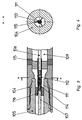
- the system for transmission of electrical signals and Electric power for a steerable horizontal drill consists of a drive adapter 10, a linkage adapter 100 and a consumer adapter 200.
- the drive adapter 10 serves to transmit the electrical Signals from the rotating drill pipe 11 on a fixed with a data processing unit (not shown) associated pantograph 12.
- Der Current collector 12 is arranged on a holder 13 so that it rests on a slip ring 14, the on a linkage connection 15 is arranged and with this and rotated with the linkage 11 about the linkage axis.
- a cable 16 emerges centrally from the linkage 11 and in a central bore in the rod connection 15 a. Via an outlet opening 18 in the wall of the linkage connection 15 is the cable 16 from the drive adapter 10 led out.
- the outlet opening 18 is with a sealing screw 19 against the escape of drilling fluid sealed.
- the cable 16 is from the sealing screw 19 led to a slip ring terminal 20.
- the slip ring terminal 20 is in direct contact with the slip ring 14 and rotates with this the rod axis.
- the slip ring 14 is axially displaceable or adjustable stored on the rod connection 15 and in his Width dimensioned so that the contact with the pantograph 12 even with an axial displacement of the slip ring persists.
- the linkage adapter 100 has in the region of the linkage connection 103 a rod socket 104 with electrical Plugs 105.
- the plug 105 connect within the Rod sections 101,102 running on its axis electrical lines 106, 107 (coaxial cable). Furthermore
- the rod sections have 101,102 different Channels 108, 109 (annular gap for conduction medium) for various Media.
- the electrical connector 105 is against the e.g. Channels 108, 109 containing liquid media sealed. The media can also be transferred use of impulses.
- the electrical connector consists of a Plug 111 and a box 112, which when connecting Sliding into each other and thus a safe make electrical contact.
- This connection can be designed as a swirl coupling.
- the electrical connectors are through a seal 113th and a seal 114 sealed against its environment.
- the connectors or cables are with cable locks 115,116 fixed so that the flow of media in the channels 108,109 is not hindered.
- the additional Ring channel 109 allows the separate transport of two different media.
- the linkage member preferably has on one side an outer and on the other side preferably one Inner thread. So a drill string can consist of several Be composed of single rods.
- a measuring device arranged in the region of the drill head can Therefore, for example, when the drill head a specific Has traveled and whose position is determined is to be connected to a power source by the rod protruding from the bore (Fig. 1, Item 11) to the machine or data recycling unit or power source is connected.
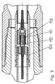
- the consumer adapter is in the housing 205 of a drill (not shown) a transmitter 215 in a cylindrical Chamber 210 arranged.
- the transmitter 215 has cylindrical housing, whose outer diameter is less than the inner diameter of the chamber 210. With the help of slip rings 220, the transmitter 215 is in the chamber 210 stored that it is axially displaceable.
- the axial movement of the transmitter 215 within the cylindrical Chamber 210 is in a damper mount 225th arranged damper 230 buffered, which is connected to a metallic Plugs 235 abut.
- the Connection consists of a ground spring 296, which is supported on the metallic plug 235 and is slidably mounted.
- the stopper is in Contact with the housing 205 and thus with the Housing surrounding soil.
- the illustrated rear portion of the transmitter 215 has Connecting elements 290,295,296,297,298 for connecting the transmitter with a power source and / or a data processing unit via a supply cable 255 on.
- these connecting elements are constructed in such a way that a cable 297 issuing from the transmitter by means of a crimp 295 threaded with a Sliding bush 290 is screwed.
- the sliding bush 290 and crimp 295 are through backup rings 285 and 298 supported within the cylindrical chamber and isolated against the damper socket 225.
- the sliding bush 290 is for receiving a plug 270 formed, which is connected to the connection cable 255 is.
- a plug socket 245 serves to fix the Plug 270 in the drill housing. Because the plug socket 245 is grounded, the plug is via an isolation socket 275 insulated against the housing.
- the rod side end of the plug is usually supplied with a drilling fluid from the linkage passed the transmitter over an outlet nozzle on the drill head becomes. Therefore, the transmitter is via a sealing element 265 sealed against penetration of the drilling fluid.
- the sealing element 265 is above a pressure plate 250 and a union nut 260 to the rod end of the Connector 270 squeezed.
- the plug 270 introduced into the sliding bush 290 For connecting the transmitter 215 to the power source and / or a data processing unit becomes the plug 270 introduced into the sliding bush 290.
- the diameters the plug 270 and the sliding bush 290 are chosen on the one hand a safe electrical contact and on the other hand an axial displaceability of the Plug 270 relative to the slide bushing 290comes.
- the plug 270 and the sliding bushing 290 can be included Replace wear easily. To exchange of the plug 270, only the nut 260 must and the fastening nut 240 are loosened.
- connection cable 255 possible without removing the transmitter 215 from its housing to have, as previously required.
- the grounding of the transmitter the for example, via a spring, displaceable be stored, so that here too no power transmission at an axial displacement of the transmitter 215 to the grounding element takes place.
- the consumer adapter according to the invention thus allows a problem-free use of electrical consumers, such as a location transmitter in a beating or temporarily beating drill.
- the system provides for the transmission of electrical Signals or electric current with his Elements, individually or in combination, a reliable Possibility of a line connection between sensors in the drill head and external recycling equipment as well between any kind of consumers within the hole and a voltage source.
Landscapes
- Engineering & Computer Science (AREA)
- Life Sciences & Earth Sciences (AREA)
- Geology (AREA)
- Mining & Mineral Resources (AREA)
- Mechanical Engineering (AREA)
- Physics & Mathematics (AREA)
- Environmental & Geological Engineering (AREA)
- Fluid Mechanics (AREA)
- General Life Sciences & Earth Sciences (AREA)
- Geochemistry & Mineralogy (AREA)
- Earth Drilling (AREA)
Claims (24)
- Système de transmission de données ou de courant électrique pour un appareil de forage horizontal dirigeable destiné à la pose et/ou au remplacement destructeur de conduites d'alimentation, comprenant une tête de forage, un entraínement, un train de tiges, un utilisateur, un adaptateur (10) d'entraínement, un adaptateur (100) de train de tiges et un adaptateur (200) d'utilisateur, caractérisé en ce quel'adaptateur (10) d'entraínement présente un élément (14) de liaison électrique stationnaire par rapport au train de tiges et un collecteur de courant (12) stationnaire par rapport à l'unité d'exploitation de données ou à la source de tension électrique,l'adaptateur de train de tiges est réalisé sous forme d'élément (101,102) de train de tiges avec une tête de train de tiges à chacune des extrémités et une ligne électrique intérieure (106, 107), et les extrémités de ligne sont immobilisées dans la tête de train de tiges des éléments (101,102) de train de tiges et orientées de telle sorte que l'assemblage de deux éléments (101,102) de train de tiges engendre une liaison automatique des lignes (106, 107), etl'adaptateur (200) d'utilisateur présente un élément de liaison (270) côté câble et un élément de liaison (290) côté utilisateur, relié au précédent, et les éléments de liaison (270, 290) permettent un mouvement axial relatif entre l'utilisateur électrique (215) et le câble de liaison (255).
- Adaptateur pour la transmission de données ou de courant électrique entre un élément de train de tiges d'un appareil de forage horizontal dirigeable destiné à la pose et/ou au remplacement destructeur de conduites d'alimentation et une unité d'exploitation de données ou une source de tension électrique, caractérisé par un élément (14) de liaison électrique stationnaire par rapport au train de tiges et un collecteur de courant (12) stationnaire par rapport à l'unité d'exploitation de données ou à la source de tension électrique et en contact avec l'élément de liaison électrique.
- Adaptateur selon la revendication 2, caractérisé en ce que l'élément de liaison électrique est réalisé sous forme de bague collectrice (14).
- Adaptateur selon la revendication 2 ou 3, caractérisé en ce que l'élément (14) de liaison électrique est monté avec possibilité de réglage ou de déplacement axial par rapport à l'axe du train de tiges.
- Adaptateur selon l'une des revendications 2 à 4, caractérisé en ce que le collecteur de courant (12) est monté à déplacement axial par rapport à l'axe du train de tiges.
- Élément de train de tiges avec une tête de train de tiges à chacune des extrémités et une ligne électrique intérieure, caractérisé en ce que les extrémités de ligne sont immobilisées dans la tête (101,102) de train de tiges et orientées de telle sorte que l'assemblage de deux éléments (101,102) de train de tiges engendre une liaison automatique des lignes.
- Élément de train de tiges selon la revendication 6, caractérisé en ce que la ligne (106, 107) s'étend axialement dans l'élément de train de tiges et est située centralement dans la tête (101,102) de train de tiges.
- Élément de train de tiges selon la revendication 6 ou 7, caractérisé par un câble coaxial (106, 107) ou un câble à toron isolé.
- Élément de train de tiges selon l'une des revendications 6 à 8, caractérisé en ce que la ligne électrique (106, 107) s'étend dans un tube intérieur pourvu d'un passage annulaire pour un fluide de conduite (108) et est isolée en étanchéité vis-à-vis de cette espace.
- Élément de train de tiges selon l'une des revendications 6 à 9, caractérisé en ce que l'élément de train de tiges présente un autre passage annulaire pour un fluide (109) entre son enveloppe extérieure et le tube intérieur.
- Élément de train de tiges selon l'une des revendications 6 à 10, caractérisé en ce que l'élément de train de tiges possède un filetage extérieur sur un côté et un filetage intérieur sur le côté opposé.
- Élément de train de tiges selon la revendication 11, caractérisé en ce que les lignes qui sont immobilisées dans l'élément de train de tiges possèdent une prise femelle d'accouplement (112) sur le côté et une prise mâle d'accouplement (111) sur le côté opposé.
- Élément de train de tiges selon la revendication 12, caractérisé en ce que la prise femelle (112) et la prise mâle (111) d'accouplement des lignes se trouvent en contact glissant lorsque le train de tiges est assemblé et lors de l'assemblage du train de tiges.
- Élément de train de tiges selon une ou plusieurs des revendications 6 à 13, caractérisé en ce qu'un élément d'étanchéité (113 ; 114) est disposé entre la prise femelle (112) et la prise mâle (111) d'accouplement.
- Élément de train de tiges selon la revendication 12 ou 13, caractérisé en ce que les accouplements (111, 112) sont réalisés sous forme d'accouplements pivotants.
- Élément de train de tiges selon une ou plusieurs des revendications 6 à 15, caractérisé en ce qu'une ligne de train de tiges est constituée de plusieurs trains de tiges individuels.
- Procédé de forage sans tranchée à l'aide d'éléments de train de tige selon l'une des revendications 9 à 16, caractérisé en ce que le tube intérieur ou encore le fluide qui s'y trouve est utilisé pour transmettre des impulsions.
- Raccord de câble pour relier des utilisateurs électriques disposés dans un appareil de forage à une source externe de courant électrique ou à une unité externe d'exploitation de données, caractérisé par un élément de liaison (270) côté câble et un élément de liaison (290) côté utilisateur, relié au précédent, les éléments de liaison (270, 290) permettant un mouvement axial relatif entre l'utilisateur électrique (215) et le câble de liaison (255).
- Raccord de câble selon la revendication 18, caractérisé par une prise mâle (270) et une prise femelle glissante (290).
- Raccord de câble selon la revendication 18 ou 19, caractérisé en ce que la prise femelle glissante (290) est disposée côté émetteur.
- Raccord de câble selon une ou plusieurs des revendications 18 à 20, caractérisé en ce que l'élément de liaison (290) est vissé sur l'utilisateur électrique (215).
- Raccord de câble selon une ou plusieurs des revendications 18 à 21, caractérisé en ce que l'élément d'étanchéité (265) assure l'étanchéité de la chambre d'émetteur (210) contre la pénétration de liquide de forage.
- Raccord de câble selon une ou plusieurs des revendications 18 à 22, caractérisé en ce que l'émetteur (215) est mis à la terre par l'intermédiaire d'un ressort (296).
- Raccord de câble selon la revendication 23, caractérisé en ce que le ressort (296) est monté avec possibilité de déplacement.
Applications Claiming Priority (6)
| Application Number | Priority Date | Filing Date | Title |
|---|---|---|---|
| DE19745368 | 1997-10-14 | ||
| DE19745368 | 1997-10-14 | ||
| DE19757512 | 1997-12-23 | ||
| DE19757512 | 1997-12-23 | ||
| DE19819626 | 1998-05-04 | ||
| DE19819626A DE19819626C2 (de) | 1997-10-14 | 1998-05-04 | Datenübertragungssystem |
Publications (3)
| Publication Number | Publication Date |
|---|---|
| EP0909876A2 EP0909876A2 (fr) | 1999-04-21 |
| EP0909876A3 EP0909876A3 (fr) | 2002-07-17 |
| EP0909876B1 true EP0909876B1 (fr) | 2005-12-21 |
Family
ID=27217822
Family Applications (1)
| Application Number | Title | Priority Date | Filing Date |
|---|---|---|---|
| EP98119278A Expired - Lifetime EP0909876B1 (fr) | 1997-10-14 | 1998-10-13 | Système de transmission de données ou de courant électrique pour un appareil de forage |
Country Status (5)
| Country | Link |
|---|---|
| US (2) | US6402524B2 (fr) |
| EP (1) | EP0909876B1 (fr) |
| JP (1) | JPH11219743A (fr) |
| AU (1) | AU752695B2 (fr) |
| CA (1) | CA2250323A1 (fr) |
Families Citing this family (42)
| Publication number | Priority date | Publication date | Assignee | Title |
|---|---|---|---|---|
| US6845822B2 (en) * | 1999-05-24 | 2005-01-25 | Merlin Technology, Inc | Auto-extending/retracting electrically isolated conductors in a segmented drill string |
| GB2377951B (en) | 2001-07-25 | 2004-02-04 | Schlumberger Holdings | Method and system for drilling a wellbore having cable based telemetry |
| US20080012569A1 (en) * | 2005-05-21 | 2008-01-17 | Hall David R | Downhole Coils |
| US7535377B2 (en) * | 2005-05-21 | 2009-05-19 | Hall David R | Wired tool string component |
| US8264369B2 (en) * | 2005-05-21 | 2012-09-11 | Schlumberger Technology Corporation | Intelligent electrical power distribution system |
| US7504963B2 (en) * | 2005-05-21 | 2009-03-17 | Hall David R | System and method for providing electrical power downhole |
| US7268697B2 (en) * | 2005-07-20 | 2007-09-11 | Intelliserv, Inc. | Laterally translatable data transmission apparatus |
| US20070044959A1 (en) * | 2005-09-01 | 2007-03-01 | Baker Hughes Incorporated | Apparatus and method for evaluating a formation |
| US7404725B2 (en) * | 2006-07-03 | 2008-07-29 | Hall David R | Wiper for tool string direct electrical connection |
| US7649475B2 (en) * | 2007-01-09 | 2010-01-19 | Hall David R | Tool string direct electrical connection |
| US7488194B2 (en) | 2006-07-03 | 2009-02-10 | Hall David R | Downhole data and/or power transmission system |
| US7617877B2 (en) * | 2007-02-27 | 2009-11-17 | Hall David R | Method of manufacturing downhole tool string components |
| US7934570B2 (en) * | 2007-06-12 | 2011-05-03 | Schlumberger Technology Corporation | Data and/or PowerSwivel |
| WO2009133474A2 (fr) * | 2008-04-08 | 2009-11-05 | Schlumberger Canada Limited | Système connecteur de tube de forage câblé |
| US8237584B2 (en) * | 2008-04-24 | 2012-08-07 | Schlumberger Technology Corporation | Changing communication priorities for downhole LWD/MWD applications |
| ITTO20090306A1 (it) * | 2009-04-20 | 2010-10-21 | Trevi Spa | Asta di perforazione con contatti elettrici |
| AT508272B1 (de) * | 2009-06-08 | 2011-01-15 | Advanced Drilling Solutions Gmbh | Vorrichtung zum verbinden von elektrischen leitungen |
| RU2423609C1 (ru) * | 2009-12-14 | 2011-07-10 | Владимир Даниилович Москвичев | Линия связи для забойных телеметрических систем контроля параметров бурения |
| DE102010019514B4 (de) | 2010-05-06 | 2014-07-03 | Tracto-Technik Gmbh & Co. Kg | Erdbohrvorrichtung und Bohrgestänge |
| IT1400540B1 (it) * | 2010-05-28 | 2013-06-11 | Pe Gas Us S R L | Connettore elettrico, in particolare per una batteria di trivellazione. |
| US9004161B2 (en) | 2010-08-06 | 2015-04-14 | Baker Hughes Incorporated | Apparatus and methods for real time communication in drill strings |
| US8893822B2 (en) | 2010-08-06 | 2014-11-25 | Baker Hughes Incorporated | Apparatus and methods for real time communication between drill bit and drilling assembly |
| US9334698B2 (en) | 2011-06-28 | 2016-05-10 | Utah Valley University | Drill rod shock tool |
| US9267346B2 (en) * | 2012-07-02 | 2016-02-23 | Robertson Intellectual Properties, LLC | Systems and methods for monitoring a wellbore and actuating a downhole device |
| FI123928B (en) | 2012-09-06 | 2013-12-31 | Robit Rocktools Ltd | Method of drillhole exploration, drill arrangement, and drillhole exploration configuration |
| DE102015001969A1 (de) | 2015-02-19 | 2016-08-25 | TRACTO-TECHNlK GmbH & Co. KG | Doppelrohrgestängeabschnitt, Doppelrohrgestängeschuss und Verfahren zum Ausbilden einer elektrisch leitfähigen Verbindung in einem Doppelrohrgestängeabschnitt |
| CN106246168B (zh) | 2016-08-29 | 2017-09-19 | 中国科学院地质与地球物理研究所 | 一种近钻头钻具姿态随钻测量装置及测量方法 |
| CN106246163B (zh) | 2016-08-31 | 2017-07-14 | 中国科学院地质与地球物理研究所 | 近钻头动态井斜测量方法及装置 |
| CN106246167B (zh) | 2016-08-31 | 2017-07-14 | 中国科学院地质与地球物理研究所 | 近钻头恒功率无线短传方法及装置 |
| CN106246169B (zh) | 2016-08-31 | 2017-09-01 | 中国科学院地质与地球物理研究所 | 一种适用于井下近钻头无线短传发射的机械装置 |
| CN106223937B (zh) * | 2016-08-31 | 2017-09-29 | 中国科学院地质与地球物理研究所 | 一种适用于井下近钻头无线短传的接收装置 |
| CN106527969B (zh) | 2016-09-21 | 2017-09-19 | 中国科学院地质与地球物理研究所 | 一种寿命均衡的NandFlash存储器读写方法 |
| CN106640055B (zh) | 2016-11-21 | 2017-11-17 | 中国科学院地质与地球物理研究所 | 一种适用于随钻方位声波测井的接收装置 |
| CN106522925B (zh) | 2016-11-21 | 2018-04-13 | 中国科学院地质与地球物理研究所 | 一种随钻方位声波信号接收换能器封装装置 |
| CN106869907B (zh) | 2017-01-19 | 2019-08-06 | 中国科学院地质与地球物理研究所 | 基于电场理论的近钻头无线短传地面环境下标定方法 |
| US10578754B2 (en) | 2017-01-19 | 2020-03-03 | Institute Of Geology And Geophysics, Chinese Academy Of Sciences | Sinusoidal excitation method and apparatus for multi-pole acoustic logging while drilling |
| CN108457602B (zh) * | 2017-12-18 | 2019-09-03 | 中国石油天然气集团公司 | 一种可释放连接器 |
| US11401750B2 (en) | 2019-09-20 | 2022-08-02 | The Charles Machine Works, Inc. | Telemetry pipe system |
| EP3923421A1 (fr) * | 2020-06-09 | 2021-12-15 | Afag Holding AG | Dispositif de raccordement électrique à un corps de base et à un corps coulissant |
| CN112652930B (zh) * | 2020-11-30 | 2022-05-24 | 中国石油天然气集团有限公司 | 一种接触式过线马达转换抵消总成及电信号传输方法 |
| CN112412438A (zh) * | 2020-12-18 | 2021-02-26 | 西南石油大学 | 一种井底积液实时监测系统 |
| DE102022128041A1 (de) * | 2022-10-24 | 2024-04-25 | Tracto-Technik Gmbh & Co. Kg | Zwei-Leiter-System für Erdbohrgestängeschüsse |
Family Cites Families (26)
| Publication number | Priority date | Publication date | Assignee | Title |
|---|---|---|---|---|
| US1794291A (en) * | 1928-08-02 | 1931-02-24 | Hobart Brothers Co | Brush support for electrical apparatus |
| US2224439A (en) * | 1937-12-13 | 1940-12-10 | Joseph H Reynolds | Apparatus for earth boring |
| US2643087A (en) * | 1950-12-22 | 1953-06-23 | Standard Oil Dev Co | Self-powered rotary drilling apparatus |
| US2681564A (en) * | 1953-04-23 | 1954-06-22 | Jr James R Jeromson | Painted slip ring structure and method of making same |
| US3087038A (en) * | 1959-10-19 | 1963-04-23 | Raymond W Bethke | Electric current interchange contact |
| US3793606A (en) * | 1973-01-02 | 1974-02-19 | Ite Imperial Corp | Squeeze coil spring and current transfer means |
| US4399877A (en) | 1981-04-17 | 1983-08-23 | Nl Sperry Sun, Inc. | Continuous borehole telemetry system and method |
| FR2544559B1 (fr) * | 1982-11-09 | 1985-10-25 | Labinal | Connecteur electrique etanche |
| US4606603A (en) * | 1983-04-07 | 1986-08-19 | Lockheed Corporation | Underwater connector including integral bladder and seal with a set of constricting means |
| US4600062A (en) * | 1984-07-13 | 1986-07-15 | 501 Dailey Petroleum Services Corporation | Shock absorbing drilling tool |
| US4660910A (en) * | 1984-12-27 | 1987-04-28 | Schlumberger Technology Corporation | Apparatus for electrically interconnecting multi-sectional well tools |
| US4676563A (en) * | 1985-05-06 | 1987-06-30 | Innotech Energy Corporation | Apparatus for coupling multi-conduit drill pipes |
| FR2582453B1 (fr) * | 1985-05-21 | 1987-09-18 | Labinal | Joint pour la realisation d'un connecteur electrique etanche et connecteur realise avec un tel joint |
| US4905773A (en) | 1987-11-02 | 1990-03-06 | Underground Technologies | Self-propelled subsoil penetrating tool system |
| DE8809108U1 (de) | 1988-07-15 | 1988-09-01 | Schmidt, Paul, 5940 Lennestadt | Langkörper |
| US4997384A (en) * | 1989-04-17 | 1991-03-05 | Otis Engineering Corporation | Wet connector |
| US5141051A (en) * | 1991-06-05 | 1992-08-25 | Ensco Technology Company | Electrical wet connect and check valve for a drill string |
| GB2270568A (en) * | 1992-09-15 | 1994-03-16 | Crane Electronics | Torque transducer having a slipring and brush assembly |
| US5425645A (en) * | 1993-11-19 | 1995-06-20 | Remington Products Company | Electric power cord connector having two axes of movement |
| US5588916A (en) * | 1994-02-17 | 1996-12-31 | Duramax, Inc. | Torque control device for rotary mine drilling machine |
| AUPM395494A0 (en) | 1994-02-18 | 1994-03-10 | Advanced Mining Technologies Pty. Ltd. | Modular electric cable for borehole drill pipe |
| DE4438934C1 (de) | 1994-10-31 | 1995-11-16 | Tracto Technik | Ortungsvorrichtung für Rammbohrgeräte |
| US5820416A (en) * | 1996-01-04 | 1998-10-13 | Carmichael; Alan L. | Multiple contact wet connector |
| DE19613788C1 (de) | 1996-04-04 | 1998-03-05 | Tracto Technik | Verfahren und Vorrichtung zum Einziehen von Rohren oder Kabeln in eine Pilotbohrung |
| US5740127A (en) * | 1996-08-21 | 1998-04-14 | Scientific Drilling International | Pulse production and control in drill strings |
| US5823257A (en) * | 1996-10-04 | 1998-10-20 | Peyton; Mark Alan | Rotatable wet connect for downhole logging devices |
-
1998
- 1998-10-08 US US09/168,805 patent/US6402524B2/en not_active Expired - Lifetime
- 1998-10-12 AU AU88397/98A patent/AU752695B2/en not_active Ceased
- 1998-10-13 EP EP98119278A patent/EP0909876B1/fr not_active Expired - Lifetime
- 1998-10-13 CA CA002250323A patent/CA2250323A1/fr not_active Abandoned
- 1998-10-14 JP JP10292401A patent/JPH11219743A/ja active Pending
-
2002
- 2002-04-30 US US10/135,882 patent/US20030082929A1/en not_active Abandoned
Also Published As
| Publication number | Publication date |
|---|---|
| US20010012703A1 (en) | 2001-08-09 |
| JPH11219743A (ja) | 1999-08-10 |
| EP0909876A2 (fr) | 1999-04-21 |
| EP0909876A3 (fr) | 2002-07-17 |
| AU752695B2 (en) | 2002-09-26 |
| US20030082929A1 (en) | 2003-05-01 |
| US6402524B2 (en) | 2002-06-11 |
| CA2250323A1 (fr) | 1999-04-14 |
| AU8839798A (en) | 1999-05-06 |
Similar Documents
| Publication | Publication Date | Title |
|---|---|---|
| EP0909876B1 (fr) | Système de transmission de données ou de courant électrique pour un appareil de forage | |
| DE3852151T2 (de) | Elektrische Leitungseinrichtung für Rohrsysteme. | |
| AT508272B1 (de) | Vorrichtung zum verbinden von elektrischen leitungen | |
| DE2827295C2 (de) | Mitnehmerstange und Anordnung aus Mitnehmerstange, Anschlußstück und Schieberteil zur Verwendung bei einem Bohrgestänge mit Telemetrieeinrichtung | |
| EP0620565B1 (fr) | Câble coaxial à haute fréquence | |
| DE102004003479B4 (de) | Bohrgestänge für Tiefbohrungen | |
| DE19819626C2 (de) | Datenübertragungssystem | |
| DE3012292C2 (fr) | ||
| EP3828375B1 (fr) | Enrouleur de câble pour insérer un câble de données dans une corde de forage, en particulier un perçage horizontal | |
| EP4139554B1 (fr) | Dispositif de transmission de donnees et/ou de puissance sur un equipement de forage ou un treuil de manutention | |
| EP3696369B1 (fr) | Dispositif de forage du sol pour un forage dirigé par câble, procédé de forage du sol dirigé par câble et utilisation lors du forage du sol dirigé par câble | |
| DE2607164C3 (de) | Elektrische Vielfachdurchführung, insbesondere für Gewinnungsmaschinen des Untertagebergbaues | |
| DE3041337C2 (fr) | ||
| EP0440123B1 (fr) | Dispositif pour la transmission de signaux dans un trou de forage | |
| EP2564013A2 (fr) | Tringlerie de tube de forage ou de transport | |
| EP2205813B1 (fr) | Procédé et dispositif de contrôle de l'enveloppe d'une conduite tubulaire pendant sa pose dans un trou de forage rempli de liquide | |
| EP0893299A2 (fr) | Installation électrique aérienne avec construction de support du caténaire | |
| EP3259434B1 (fr) | Portion de tige de forage double, tronçon de tige de forage double et procédé pour former une liaison électriquement conductrice dans une portion de tige de forage double | |
| EP2150674B1 (fr) | Procédé et dispositif de contrôle du gainage d'une tubulure lors de l'insertion dans un trou de forage rempli de liquide | |
| EP2820228B1 (fr) | Tige de forage | |
| EP4361394B1 (fr) | Système à deux conducteurs pour éléments de tiges de forage | |
| DE2744829A1 (de) | Rohrabschnitt zur verwendung bei arbeiten in tiefbohrungen | |
| DE3032696C2 (fr) | ||
| DE1117519B (de) | Hohlbohrgestaengeverbindung fuer Tiefbohrungen mit elektrischer Leitung | |
| AT350489B (de) | Rohrabschnitt zur verwendung bei tiefbohrungen |
Legal Events
| Date | Code | Title | Description |
|---|---|---|---|
| PUAI | Public reference made under article 153(3) epc to a published international application that has entered the european phase |
Free format text: ORIGINAL CODE: 0009012 |
|
| AK | Designated contracting states |
Kind code of ref document: A2 Designated state(s): AT BE CH CY DE DK ES FI FR GB GR IE IT LI LU MC NL PT SE |
|
| AX | Request for extension of the european patent |
Free format text: AL;LT;LV;MK;RO;SI |
|
| PUAL | Search report despatched |
Free format text: ORIGINAL CODE: 0009013 |
|
| AK | Designated contracting states |
Kind code of ref document: A3 Designated state(s): AT BE CH CY DE DK ES FI FR GB GR IE IT LI LU MC NL PT SE |
|
| AX | Request for extension of the european patent |
Free format text: AL;LT;LV;MK;RO;SI |
|
| 17P | Request for examination filed |
Effective date: 20030113 |
|
| AKX | Designation fees paid |
Designated state(s): DE GB |
|
| 17Q | First examination report despatched |
Effective date: 20040422 |
|
| GRAP | Despatch of communication of intention to grant a patent |
Free format text: ORIGINAL CODE: EPIDOSNIGR1 |
|
| GRAS | Grant fee paid |
Free format text: ORIGINAL CODE: EPIDOSNIGR3 |
|
| GRAA | (expected) grant |
Free format text: ORIGINAL CODE: 0009210 |
|
| AK | Designated contracting states |
Kind code of ref document: B1 Designated state(s): DE GB |
|
| REG | Reference to a national code |
Ref country code: GB Ref legal event code: FG4D Free format text: NOT ENGLISH |
|
| REF | Corresponds to: |
Ref document number: 59813293 Country of ref document: DE Date of ref document: 20060126 Kind code of ref document: P |
|
| GBT | Gb: translation of ep patent filed (gb section 77(6)(a)/1977) |
Effective date: 20060329 |
|
| PLBE | No opposition filed within time limit |
Free format text: ORIGINAL CODE: 0009261 |
|
| STAA | Information on the status of an ep patent application or granted ep patent |
Free format text: STATUS: NO OPPOSITION FILED WITHIN TIME LIMIT |
|
| 26N | No opposition filed |
Effective date: 20060922 |
|
| PGFP | Annual fee paid to national office [announced via postgrant information from national office to epo] |
Ref country code: GB Payment date: 20141024 Year of fee payment: 17 |
|
| GBPC | Gb: european patent ceased through non-payment of renewal fee |
Effective date: 20151013 |
|
| PG25 | Lapsed in a contracting state [announced via postgrant information from national office to epo] |
Ref country code: GB Free format text: LAPSE BECAUSE OF NON-PAYMENT OF DUE FEES Effective date: 20151013 |
|
| PGFP | Annual fee paid to national office [announced via postgrant information from national office to epo] |
Ref country code: DE Payment date: 20171124 Year of fee payment: 20 |
|
| REG | Reference to a national code |
Ref country code: DE Ref legal event code: R071 Ref document number: 59813293 Country of ref document: DE |