EP0909910A2 - Threeway mixing valve - Google Patents
Threeway mixing valve Download PDFInfo
- Publication number
- EP0909910A2 EP0909910A2 EP98119275A EP98119275A EP0909910A2 EP 0909910 A2 EP0909910 A2 EP 0909910A2 EP 98119275 A EP98119275 A EP 98119275A EP 98119275 A EP98119275 A EP 98119275A EP 0909910 A2 EP0909910 A2 EP 0909910A2
- Authority
- EP
- European Patent Office
- Prior art keywords
- mixing valve
- windows
- way mixing
- plug
- connections
- Prior art date
- Legal status (The legal status is an assumption and is not a legal conclusion. Google has not performed a legal analysis and makes no representation as to the accuracy of the status listed.)
- Withdrawn
Links
Images




Classifications
-
- F—MECHANICAL ENGINEERING; LIGHTING; HEATING; WEAPONS; BLASTING
- F16—ENGINEERING ELEMENTS AND UNITS; GENERAL MEASURES FOR PRODUCING AND MAINTAINING EFFECTIVE FUNCTIONING OF MACHINES OR INSTALLATIONS; THERMAL INSULATION IN GENERAL
- F16K—VALVES; TAPS; COCKS; ACTUATING-FLOATS; DEVICES FOR VENTING OR AERATING
- F16K11/00—Multiple-way valves, e.g. mixing valves; Pipe fittings incorporating such valves
- F16K11/02—Multiple-way valves, e.g. mixing valves; Pipe fittings incorporating such valves with all movable sealing faces moving as one unit
- F16K11/08—Multiple-way valves, e.g. mixing valves; Pipe fittings incorporating such valves with all movable sealing faces moving as one unit comprising only taps or cocks
- F16K11/085—Multiple-way valves, e.g. mixing valves; Pipe fittings incorporating such valves with all movable sealing faces moving as one unit comprising only taps or cocks with cylindrical plug
- F16K11/0853—Multiple-way valves, e.g. mixing valves; Pipe fittings incorporating such valves with all movable sealing faces moving as one unit comprising only taps or cocks with cylindrical plug having all the connecting conduits situated in a single plane perpendicular to the axis of the plug
Definitions
- the present invention relates to a 3-way mixing valve according to the Generic term of patent claim 1.
- Such a mixing valve is e.g. known from DE-OS 20 38 085.
- the outer connections are 90 ° to each other offset, but the windows leading into the mixing room are offset by 120 ° to each other, which results in an interchangeability of the connecting pieces.
- the known 3-way mixing valve still requires a servomotor with an adjustment angle of 120 °.
- 4-way mixing motors require a servomotor with one Adjustment angle of 90 °. For reasons of rationalization, however, both would be desirable To be able to operate mixer types with one and the same servomotor.
- the present invention solves this problem by designing a 3-way mixing valve according to the characterizing features of claim 1.
- This configuration leads to a completely interchangeable 3-way mixing valve, the Actuator only needs an adjustment angle of 90 °.
- More beneficial Embodiments of the mixing valve according to the invention are the dependent claims removable.
- a 3-way mixing valve 10 comprises a T-shaped housing 12 with three connecting pieces 14, 16 and 18, by means of union nuts, not shown a boiler flow KV, a heating flow HV and a heating return HR can be connected.
- a removable lid not shown, is in one circular cylindrical interior 20, a mixer plug 22 is used, which around a central, Axis 24 perpendicular to the plane of the drawing is rotatable.
- the axis 24 stands here perpendicular to the intersection of the intersecting lines of symmetry of the in and Outlets.
- the three connecting pieces 14, 16, 18 open via windows 26, 28, 30 in the housing 12 in the interior 20, the centers of the windows 26, 28, 30 in each case by 120 ° to one another are offset.
- the mixer plug 22 has a closing contour 32, a regulating contour 34 on both sides the closing contour 32 and a completely open passage area 36.
- the Closing contour 32 extends over an angle that is sufficient to one each Windows 26, 28 or 30 and part of the adjacent webs formed in the housing 12 38, 40, 42 to cover in the closed position.
- the control contour 34 can vary depending on the Rule requirement extend over a variable angular range.
- FIG. 1b shows how the 3-way mixing valve 10 by rotating its mixer plug 22 out of position with a motor rotation angle M of 90 ° warm "to the other extreme position can be brought cold.
- FIGS. 2a, b show a 3-way mixing valve modified compared to FIGS. 1a, b 10 ', which is characterized by a reduced width of the webs 38', 40 ', 42', accordingly widened windows 26 ', 28', 30 'and with a mixer plug 22' a closing contour 32 'extending over a larger angle.
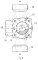
- the modification of the 3-way mixing valve 10 ′′ shown in FIG. 3 is characterized by this that the axis of rotation 24 of the mixer plug 22 has a lateral offset with respect to the Intersection of the lines of symmetry running through the connecting pieces 14, 16, 18 having. Such a design leads to a shorter connection dimension of the side Connection.
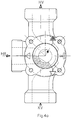
- FIGS. 4a, b, c the 3-way mixing valve 10 ′′ according to FIG. 3 is different Connection configurations shown.
- Figure 4a shows the mixing valve with straight Passage, with the connection of the boiler flow KV from below, the connection of the Heating return HR from the left and the connection of the heating flow HV from above.
- Figure 4b shows the mixing valve also with a straight passage, the Heating return HR is connected from the right and the other connections are retained were.
- FIG. 4c shows the mixing valve with an angled passage, whereby it is optionally possible to connect the side connection of Exchange heating return HR and boiler flow KV.
Landscapes
- Engineering & Computer Science (AREA)
- General Engineering & Computer Science (AREA)
- Mechanical Engineering (AREA)
- Multiple-Way Valves (AREA)
Abstract
Description
Die vorliegende Erfindung bezieht sich auf ein 3-Wege-Mischventil nach dem Gattungsbegriff des Patentanspruches 1.The present invention relates to a 3-way mixing valve according to the Generic term of patent claim 1.
In Warmwasser-Zentralheizungen gelangen heutzutage Kompakt-Mischer sowohl in 3-Wege- als auch in 4-Wege-Ausführung zur Anwendung. Hierbei wird Wert darauf gelegt, daß bei beiden Mischertypen die Anschlüsse rundum vertauschbar sind.In hot water central heating systems, compact mixers are now used both in 3-way as well as 4-way version for use. This is important placed that the connections are completely interchangeable with both mixer types.
Ein derartiges Mischventil ist z.B. aus der DE-OS 20 38 085 bekannt. Bei diesem bekannten 3-Wege-Mischventil sind die äußeren Anschlüsse zwar um 90° zueinander versetzt, die in den Mischraum führenden Fenster sind aber um 120° zueinander versetzt, wodurch sich eine Vertauschbarkeit der Anschlußstutzen ergibt. Das bekannte 3-Wege-Mischventil benötigt aber weiterhin einen Stellmotor mit einem Verstellwinkel von 120°. Andererseits benötigen 4-Wege-Mischmotoren einen Stellmotor mit einem Verstellwinkel von 90°. Aus Gründen der Rationalisierung wäre es aber erwünscht, beide Mischertypen mit ein und demselben Stellmotor betreiben zu können.Such a mixing valve is e.g. known from DE-OS 20 38 085. With this known 3-way mixing valve, the outer connections are 90 ° to each other offset, but the windows leading into the mixing room are offset by 120 ° to each other, which results in an interchangeability of the connecting pieces. The known 3-way mixing valve still requires a servomotor with an adjustment angle of 120 °. On the other hand, 4-way mixing motors require a servomotor with one Adjustment angle of 90 °. For reasons of rationalization, however, both would be desirable To be able to operate mixer types with one and the same servomotor.
Die vorliegende Erfindung löst diese Aufgabe durch eine Ausgestaltung eines 3-Wege-Mischventils gemäß den kennzeichnenden Merkmalen des Patentanspruches 1. Diese Ausgestaltung führt zu einem rundum vertauschbaren 3-Wege-Mischventil, dessen Stellmotor nur einen Verstellwinkel von 90° benötigt. Weitere vorteilhafte Ausgestaltungen des erfindungsgemäßen Mischventils sind den abhängigen Ansprüchen entnehmbar.The present invention solves this problem by designing a 3-way mixing valve according to the characterizing features of claim 1. This configuration leads to a completely interchangeable 3-way mixing valve, the Actuator only needs an adjustment angle of 90 °. More beneficial Embodiments of the mixing valve according to the invention are the dependent claims removable.
Anhand von in den Figuren der beiliegenden Zeichnung dargestellten Ausführungsbeispielen sei im folgenden die Erfindung näher erläutert. Es zeigen:
- Figuren 1a, b
- eine erste Ausführungsform eines 3-Wege-Mischventils gemäß der vorliegenden Erfindung in zwei verschiedenen Stellungen;
- Figuren 2a, b
- eine Modifikation der Ausführungsform gemäß Figur 1a, b.
- Figur 3
- eine zweite Ausführungsform eines 3-Wege-Mischventils gemäß der Erfindung; und
- Figuren 4a, b, c
- das Mischventil gemäß Figur 3 in drei verschiedenen Einbaulagen.
- Figures 1a, b
- a first embodiment of a 3-way mixing valve according to the present invention in two different positions;
- Figures 2a, b
- a modification of the embodiment according to Figure 1a, b.
- Figure 3
- a second embodiment of a 3-way mixing valve according to the invention; and
- Figures 4a, b, c
- the mixing valve according to Figure 3 in three different installation positions.
Gemäß den Figuren 1a, b umfaßt ein 3-Wege-Mischventil 10 ein T-förmiges Gehäuse 12
mit drei Anschlußstutzen 14, 16 und 18, die mittels nicht dargestellter Überwurfmuttern an
einen Kesselvorlauf KV, einen Heizungsvorlauf HV und einen Heizungsrücklauf HR
anschließbar sind. Über einen nicht-dargestellten abnehmbaren Deckel ist in einem
kreiszylindrischen Innenraum 20 ein Mischerküken 22 eingesetzt, das um eine zentrale,
senkrecht zur Zeichenebene stehende Achse 24 drehbar ist. Die Achse 24 steht hierbei
senkrecht zu dem Schnittpunkt der sich schneidenden Symmetrielinien der Ein- und
Auslässe.According to FIGS. 1a, b, a 3-
Die drei Anschlußstutzen 14, 16, 18 münden über Fenster 26, 28, 30 in dem Gehäuse 12 in
den Innenraum 20, wobei die Mitten der Fenster 26, 28, 30 jeweils um 120° zueinander
versetzt sind.The three connecting
Das Mischerküken 22 weist eine Schließkontur 32, eine Regelkontur 34 zu beiden Seiten
der Schließkontur 32 und einen vollständig offenen Durchlaßbereich 36 auf. Die
Schließkontur 32 erstreckt sich über einen Winkel, der ausreichend ist, um jeweils ein
Fenster 26, 28 oder 30 und einen Teil der angrenzenden, im Gehäuse 12 angeformten Stege
38, 40, 42 in der Schließstellung zu überdecken. Die Regelkontur 34 kann sich je nach der
Regelanforderung über einen variablen Winkelbereich erstrecken.The
Um das Ventil mittels einer Motordrehung um 90° (Stellwinkel M) von der in Figur 1a
gezeigten Stellung, in der der Kesselvorlauf KV voll mit dem Heizungsvorlauf HV
verbunden ist (Warm-Stellung), in die entgegengesetzte in Figur 1b gezeigte Stellung zu
bringen, in der der Heizungsrücklauf HR mit dem Heizungsvorlauf HV voll verbunden ist
(Kalt-Stellung), muß die Bedingung erfüllt sein, daß die maximale Fensteröffnung -
gebildet aus der gemeinsamen Öffnung von Mischerküken 22 und Gehäuse 12 - sich über
höchstens 90° erstreckt. To the valve by means of a motor rotation by 90 ° (setting angle M) from that in Figure 1a
shown position, in which the boiler flow KV full with the heating flow HV
is connected (warm position) to the opposite position shown in Figure 1b
bring in which the heating return HR is fully connected to the heating flow HV
(Cold position), the condition must be met that the maximum window opening -
formed from the common opening of
In Figur 1b ist gezeigt, wie mit einem Motor-Drehwinkel M von 90° das
3-Wege-Mischventil 10 durch Drehung seines Mischerkükens 22 aus der Stellung 
In den Figuren 2a, b ist ein gegenüber den Figuren 1a, b modifiziertes 3-Wege-Mischventil 10' dargestellt, das sich durch eine verringerte Breite der Stege 38', 40', 42', dementsprechend verbreiterte Fenster 26', 28', 30' und durch ein Mischerküken 22' mit einer sich über einen größeren Winkel erstrecken Schließkontur 32' auszeichnet.FIGS. 2a, b show a 3-way mixing valve modified compared to FIGS. 1a, b 10 ', which is characterized by a reduced width of the webs 38', 40 ', 42', accordingly widened windows 26 ', 28', 30 'and with a mixer plug 22' a closing contour 32 'extending over a larger angle.
Aber auch hier muß die vorstehend erwähnte Bedingung erfüllt sein, damit das Mischventil
mit einem Motor-Drehwinkel M von 90° aus der Stellung
Die in Figur 3 gezeigte Modifikation des 3-Wege-Mischventiles 10'' zeichnet sich dadurch
aus, daß die Drehachse 24 des Mischerkükens 22 einen seitlichen Versatz gegenüber dem
Schnittpunkt der durch die Anschlußstutzen 14, 16, 18 verlaufenden Symmetrielinien
aufweist. Eine solche Bauform führt zu einem kürzeren Anschlußmaß des seitlichen
Anschlusses.The modification of the 3-
In den Figuren 4a, b, c ist das 3-Wege-Mischventil 10'' gemäß Figur 3 in verschiedenen
Anschlußkonfigurationen dargestellt. So zeigt Figur 4a das Mischventil mit geradem
Durchgang, mit dem Anschluß des Kesselvorlaufes KV von unten, dem Anschluß des
Heizungsrücklaufes HR von links und dem Anschluß des Heizungsvorlaufes HV von oben.
Figur 4b zeigt das Mischventil ebenfalls mit geradem Durchgang, wobei der
Heizungsrücklauf HR von rechts angeschlossen ist und die übrigen Anschlüsse beibehalten
wurden. Schließlich zeigt Figur 4c das Mischventil mit abgewinkeltem Durchgang, wobei
es wahlweise möglich ist, bei Heizungsvorlauf HV nach oben den seitlichen Anschluß von
Heizungsrücklauf HR und Kesselvorlauf KV zu vertauschen.In FIGS. 4a, b, c, the 3-
Claims (5)
Applications Claiming Priority (2)
| Application Number | Priority Date | Filing Date | Title |
|---|---|---|---|
| DE19745913 | 1997-10-17 | ||
| DE1997145913 DE19745913C1 (en) | 1997-10-17 | 1997-10-17 | 3-way mixing valve |
Publications (2)
| Publication Number | Publication Date |
|---|---|
| EP0909910A2 true EP0909910A2 (en) | 1999-04-21 |
| EP0909910A3 EP0909910A3 (en) | 1999-07-21 |
Family
ID=7845836
Family Applications (1)
| Application Number | Title | Priority Date | Filing Date |
|---|---|---|---|
| EP98119275A Withdrawn EP0909910A3 (en) | 1997-10-17 | 1998-10-13 | Threeway mixing valve |
Country Status (2)
| Country | Link |
|---|---|
| EP (1) | EP0909910A3 (en) |
| DE (1) | DE19745913C1 (en) |
Cited By (5)
| Publication number | Priority date | Publication date | Assignee | Title |
|---|---|---|---|---|
| WO2006013449A1 (en) * | 2004-07-30 | 2006-02-09 | Adriaan Francois Roberts | A swimming pool installation and accessory |
| EP1862712A1 (en) * | 2006-06-02 | 2007-12-05 | Emech Control Limited | Mixing valve and mixing device |
| CN103968106A (en) * | 2013-02-05 | 2014-08-06 | 沈如华 | Color mixer and reversing valve device thereof |
| CN105570146A (en) * | 2015-11-06 | 2016-05-11 | 钱月珍 | Automatic pressurizing water mixing valve for hot water |
| PL132090U1 (en) * | 2024-04-08 | 2025-10-13 | Lanica Adam Phu Landam | Two-way three-way valve for pipe blow-off |
Family Cites Families (4)
| Publication number | Priority date | Publication date | Assignee | Title |
|---|---|---|---|---|
| FR817912A (en) * | 1936-05-18 | 1937-09-14 | Pepin Fils | Multi-way valve |
| DE1750910A1 (en) * | 1968-06-18 | 1971-04-22 | Walter Stegmann | Three-way cock with U-chicks |
| DE2038085A1 (en) * | 1970-07-31 | 1972-02-10 | Centra Buerkle Kg Albert | Three-way mixer tap |
| DE2350375C3 (en) * | 1973-10-08 | 1983-12-08 | Centra-Bürkle GmbH & Co, 7036 Schönaich | Mixing or diverting valve |
-
1997
- 1997-10-17 DE DE1997145913 patent/DE19745913C1/en not_active Expired - Lifetime
-
1998
- 1998-10-13 EP EP98119275A patent/EP0909910A3/en not_active Withdrawn
Cited By (7)
| Publication number | Priority date | Publication date | Assignee | Title |
|---|---|---|---|---|
| WO2006013449A1 (en) * | 2004-07-30 | 2006-02-09 | Adriaan Francois Roberts | A swimming pool installation and accessory |
| EP1862712A1 (en) * | 2006-06-02 | 2007-12-05 | Emech Control Limited | Mixing valve and mixing device |
| CN103968106A (en) * | 2013-02-05 | 2014-08-06 | 沈如华 | Color mixer and reversing valve device thereof |
| CN103968106B (en) * | 2013-02-05 | 2016-08-10 | 沈如华 | Colour mixer and change valve device thereof |
| CN105570146A (en) * | 2015-11-06 | 2016-05-11 | 钱月珍 | Automatic pressurizing water mixing valve for hot water |
| CN105570146B (en) * | 2015-11-06 | 2017-11-21 | 新昌县羽林街道鑫博机械厂 | Hot water Automatic-boosting water mixing valve |
| PL132090U1 (en) * | 2024-04-08 | 2025-10-13 | Lanica Adam Phu Landam | Two-way three-way valve for pipe blow-off |
Also Published As
| Publication number | Publication date |
|---|---|
| DE19745913C1 (en) | 1999-04-22 |
| EP0909910A3 (en) | 1999-07-21 |
Similar Documents
| Publication | Publication Date | Title |
|---|---|---|
| EP0162342B1 (en) | Control insert for sanitary mixing battery | |
| DE60019481T2 (en) | Folding arrangement and fluid circulation and distribution device with such an arrangement | |
| DE69100274T2 (en) | Device for ventilation and heating of the passenger compartment of a motor vehicle. | |
| DE102020202520A1 (en) | Distribution valve and cooling system | |
| DE60022787T2 (en) | MULTIPLE VALVE | |
| AT393041B (en) | THERMOSTATIC MIXING VALVE | |
| DE2007226A1 (en) | Ventilation device, in particular for motor vehicles | |
| EP0667472B1 (en) | Modular valve and delivery system for fluids | |
| EP1022635A1 (en) | Sanitary thermostatic valve | |
| EP1022634A1 (en) | Cartridge for sanitary fittings | |
| EP1319144B1 (en) | Cartridge for sanitary appliances | |
| DE68904757T2 (en) | BALL VALVE. | |
| DE19745913C1 (en) | 3-way mixing valve | |
| DE60216583T2 (en) | OPERATING DEVICE OF THE OPENING ANGLE OF THE VENTILATION FLAPS OF A VEHICLE VENTILATION / AIR CONDITIONING GROUP | |
| DE19834575C5 (en) | Rotary valve | |
| DE3525053C2 (en) | ||
| DE2313645B2 (en) | Control valve | |
| DE1650407A1 (en) | Multi-way control valve | |
| DE19709534A1 (en) | Radiator for fluid medium | |
| EP0916911A2 (en) | Connection fitting and radiator | |
| EP0373145A1 (en) | Internal-combustion engine with two valves per cylinder | |
| DE3828206C1 (en) | ||
| DE2946383C2 (en) | Four-way valve for the cooling circuit of motor vehicles | |
| DE1600995B2 (en) | OPTIONAL REUSABLE MIXING TAP FOR LEFT OR RIGHT CONNECTION | |
| DE9412801U1 (en) | Radiator arrangement |
Legal Events
| Date | Code | Title | Description |
|---|---|---|---|
| PUAI | Public reference made under article 153(3) epc to a published international application that has entered the european phase |
Free format text: ORIGINAL CODE: 0009012 |
|
| AK | Designated contracting states |
Kind code of ref document: A2 Designated state(s): AT BE CH CY DE DK ES FI FR GB GR IE IT LI LU MC NL PT SE |
|
| AX | Request for extension of the european patent |
Free format text: AL;LT;LV;MK;RO;SI |
|
| PUAL | Search report despatched |
Free format text: ORIGINAL CODE: 0009013 |
|
| AK | Designated contracting states |
Kind code of ref document: A3 Designated state(s): AT BE CH CY DE DK ES FI FR GB GR IE IT LI LU MC NL PT SE |
|
| AX | Request for extension of the european patent |
Free format text: AL;LT;LV;MK;RO;SI |
|
| RTI1 | Title (correction) |
Free format text: THREEWAY MIXING VALVE |
|
| AKX | Designation fees paid | ||
| REG | Reference to a national code |
Ref country code: DE Ref legal event code: 8566 |
|
| STAA | Information on the status of an ep patent application or granted ep patent |
Free format text: STATUS: THE APPLICATION IS DEEMED TO BE WITHDRAWN |
|
| 18D | Application deemed to be withdrawn |
Effective date: 20000122 |