EP0909921A1 - Brenner für den Betrieb eines Wärmeerzeugers - Google Patents
Brenner für den Betrieb eines Wärmeerzeugers Download PDFInfo
- Publication number
- EP0909921A1 EP0909921A1 EP97810773A EP97810773A EP0909921A1 EP 0909921 A1 EP0909921 A1 EP 0909921A1 EP 97810773 A EP97810773 A EP 97810773A EP 97810773 A EP97810773 A EP 97810773A EP 0909921 A1 EP0909921 A1 EP 0909921A1
- Authority
- EP
- European Patent Office
- Prior art keywords
- burner
- burner according
- flow
- downstream
- fuel
- Prior art date
- Legal status (The legal status is an assumption and is not a legal conclusion. Google has not performed a legal analysis and makes no representation as to the accuracy of the status listed.)
- Granted
Links
Images


Classifications
-
- F—MECHANICAL ENGINEERING; LIGHTING; HEATING; WEAPONS; BLASTING
- F23—COMBUSTION APPARATUS; COMBUSTION PROCESSES
- F23D—BURNERS
- F23D11/00—Burners using a direct spraying action of liquid droplets or vaporised liquid into the combustion space
- F23D11/36—Details
- F23D11/40—Mixing tubes; Burner heads
- F23D11/402—Mixing chambers downstream of the nozzle
-
- F—MECHANICAL ENGINEERING; LIGHTING; HEATING; WEAPONS; BLASTING
- F23—COMBUSTION APPARATUS; COMBUSTION PROCESSES
- F23C—METHODS OR APPARATUS FOR COMBUSTION USING FLUID FUEL OR SOLID FUEL SUSPENDED IN A CARRIER GAS OR AIR
- F23C7/00—Combustion apparatus characterised by arrangements for air supply
- F23C7/002—Combustion apparatus characterised by arrangements for air supply the air being submitted to a rotary or spinning motion
-
- F—MECHANICAL ENGINEERING; LIGHTING; HEATING; WEAPONS; BLASTING
- F23—COMBUSTION APPARATUS; COMBUSTION PROCESSES
- F23D—BURNERS
- F23D14/00—Burners for combustion of a gas, e.g. of a gas stored under pressure as a liquid
- F23D14/02—Premix gas burners, i.e. in which gaseous fuel is mixed with combustion air upstream of the combustion zone
-
- F—MECHANICAL ENGINEERING; LIGHTING; HEATING; WEAPONS; BLASTING
- F23—COMBUSTION APPARATUS; COMBUSTION PROCESSES
- F23D—BURNERS
- F23D14/00—Burners for combustion of a gas, e.g. of a gas stored under pressure as a liquid
- F23D14/46—Details
- F23D14/72—Safety devices, e.g. operative in case of failure of gas supply
- F23D14/78—Cooling burner parts
-
- F—MECHANICAL ENGINEERING; LIGHTING; HEATING; WEAPONS; BLASTING
- F23—COMBUSTION APPARATUS; COMBUSTION PROCESSES
- F23D—BURNERS
- F23D17/00—Burners for combustion simultaneously or alternately of gaseous or liquid or pulverulent fuel
- F23D17/002—Burners for combustion simultaneously or alternately of gaseous or liquid or pulverulent fuel gaseous or liquid fuel
-
- F—MECHANICAL ENGINEERING; LIGHTING; HEATING; WEAPONS; BLASTING
- F23—COMBUSTION APPARATUS; COMBUSTION PROCESSES
- F23D—BURNERS
- F23D23/00—Assemblies of two or more burners
-
- F—MECHANICAL ENGINEERING; LIGHTING; HEATING; WEAPONS; BLASTING
- F23—COMBUSTION APPARATUS; COMBUSTION PROCESSES
- F23C—METHODS OR APPARATUS FOR COMBUSTION USING FLUID FUEL OR SOLID FUEL SUSPENDED IN A CARRIER GAS OR AIR
- F23C2900/00—Special features of, or arrangements for combustion apparatus using fluid fuels or solid fuels suspended in air; Combustion processes therefor
- F23C2900/07002—Premix burners with air inlet slots obtained between offset curved wall surfaces, e.g. double cone burners
-
- F—MECHANICAL ENGINEERING; LIGHTING; HEATING; WEAPONS; BLASTING
- F23—COMBUSTION APPARATUS; COMBUSTION PROCESSES
- F23D—BURNERS
- F23D2900/00—Special features of, or arrangements for burners using fluid fuels or solid fuels suspended in a carrier gas
- F23D2900/14—Special features of gas burners
- F23D2900/14021—Premixing burners with swirling or vortices creating means for fuel or air
Definitions
- the invention relates to a burner for operating a heat generator according to Preamble of claim 1.
- the upstream side consists of a swirl generator, the flow formed therein seamlessly in a mixing section is transferred. This is done using one at the beginning of the Mixing section flow geometry formed for this purpose, which consists of transition channels exists, which is sectoral, according to the number of those acting Partial body of the swirl generator, capture the end face of the mixing section and in Flow direction swirl. Downstream of these transition channels the mixing section has a number of filming holes, which one Ensure an increase in the flow velocity along the pipe wall. This is followed by a combustion chamber, the transition between the Mixing section and the combustion chamber formed by a cross-sectional jump in whose plane a backflow zone or backflow bubble forms.
- the swirl strength in the swirl generator is selected so that the bursting of the vortex does not occur within the mixing section, but further downstream, as executed above, in the area of the cross-sectional jump.
- the length of the mixing section is dimensioned so that a sufficient mix quality for everyone Types of fuel is guaranteed.
- this burner compared to those from the previous state the technology a significant improvement in terms of strengthening flame stability, lower pollutant emissions, lower pulsations, complete Burnout, large operating area, good cross-ignition between the different Burners, compact design, improved mixing, etc., guaranteed, it turns out that this burner has no autonomous arrangements, to drive the gas turbine safely, especially in its transient load ranges to be able to. For example, in the partial load range, the burner must have a support flame get supported. The integration of such precautions in the burner lead to no additional pollutant emissions which the operational and emissions advantages of the underlying burner could question.
- the invention seeks to remedy this.
- the invention as set out in the claims is characterized, the task is based on a burner at the beginning to propose precautions which strengthen the flame stability for stable operation, especially in the transient load ranges, ensure always under the further task that the Pollutant emissions remain low.
- the burner is expanded in such a way that in the area of its transition a ring-shaped system for providing to the downstream combustion chamber of a fuel / air mixture is generally provided as Pilot stage acts.
- Pilot stage acts.
- Appropriate pilot burners are created in the combustion chamber, which are operated in diffusion mode for stability reasons and directly in the combustion chamber.
- This air volume initially takes over the cooling of the by means of impingement cooling side facing away from the combustion chamber before it then mixes with the gas and then as a pre-mixed flame with minimized pollutant emissions piloting the main flame in the combustion chamber is maintained.
- This impingement cooling means that the surface of the pilot gas ring is hot and largely isolated from the flame radiation from the combustion chamber, so that the thermal load in this area is significantly reduced.
- the object according to the invention also ensures that the minimized Cooling amount can also be fed to the burning process.
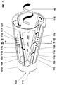
- Fig. 1 shows the overall structure of a burner.
- a swirl generator 100 is effective, the design of which is shown and described in more detail in the following FIGS. 3-6.
- This swirl generator 100 is a conical structure which is acted upon tangentially several times by a tangentially flowing combustion air flow 115.
- the flow formed here is seamlessly transferred to a transition piece 200 using a transition geometry provided downstream of the swirl generator 100, in such a way that no separation areas can occur there.
- the configuration of this transition geometry is described in more detail in FIG. 6.
- This transition piece 200 is extended on the outflow side of the transition geometry by a mixing tube 20, both parts forming the actual mixing section 220.
- the mixing section 220 can consist of a single piece, that is to say then that the transition piece 200 and the mixing tube 20 merge into a single coherent structure, the characteristics of each part being retained. If the transition piece 200 and the mixing tube 20 are created from two parts, these are connected by a bushing ring 10, the same bushing ring 10 serving as an anchoring surface for the swirl generator 100 on the head side. Such a bushing ring 10 also has the advantage that different mixing tubes can be used. On the outflow side of the mixing tube 20 is the actual combustion chamber 30 of a combustion chamber, which is here only symbolized by a flame tube.
- the mixing section 220 largely fulfills the task of providing a defined section downstream of the swirl generator 100, in which a perfect premixing of fuels of different types can be achieved.
- This mixing section i.e. the mixing pipe 20 in the foreground, furthermore enables loss-free flow guidance, so that no backflow zone or backflow bubble can initially form even in operative connection with the transition geometry, so that the length of the mixing section 220 can influence the quality of the mixture for all types of fuel .
- this mixing section 220 has yet another property, which consists in that the axial velocity profile itself has a pronounced maximum on the axis, so that the flame cannot be re-ignited from the combustion chamber. However, it is correct that with such a configuration this axial speed drops towards the wall.
- these bores 21 run at an acute angle with respect to the burner axis 60.
- the outlet of the transition channels 201 corresponds to the narrowest flow cross-section of the mixing tube 20.
- the said transition channels 201 therefore bridge the respective cross-sectional difference without adversely affecting the flow formed. If the selected precaution triggers an intolerable pressure loss when guiding the pipe flow 40 along the mixing pipe 20, this can be remedied by providing a diffuser (not shown in the figure) at the end of this mixing pipe.
- a combustion chamber 30 combustion chamber then adjoins the end of the mixing tube 20, a cross-sectional jump formed by a burner front 70 being present between the two flow cross sections.
- a pilot burner system 300 is provided concentrically with the mixing tube 20 in the area of its outlet. This consists of an inner annular chamber 301 into which a fuel, preferably a gaseous fuel 303, flows. In addition to this inner annular chamber 301, there is a second annular chamber 302 into which an air quantity 304 flows. Both annular chambers 301, 302 have individually designed through openings, such that the individual media 303, 304 flow into a common downstream annular chamber 308 due to their function.
- the transfer of the gaseous fuel 303 from the annular chamber 301 into the downstream annular chamber 308 is accomplished by a number of openings 309 arranged in the circumferential direction.
- the passage geometry of these openings 309 is designed such that the gaseous fuel 303 flows into the downstream annular chamber 308 with a large mixing potential.
- the other annular chamber 302 closes with a perforated plate 305, the bores 310 provided here being designed in such a way that the air volume 304 flowing through there impacts cooling on the base plate 307 of the downstream annular chamber 308.
- This base plate has the function of a heat protection plate against the calorific load from the combustion chamber 30, so that this impingement cooling must be extremely efficient here.
- this air mixes within this annular chamber 308 with the inflowing gaseous fuel 303 from the openings 309 of the upstream annular chamber 301 before this mixture through a number of bores 306 arranged on the combustion chamber side into the combustion chamber 30 flows out.
- the mixture flowing out burns as a premixed diffusion flame with minimized pollutant emissions and forms accordingly Bore 306 a pilot burner acting in the combustion chamber 30, which one guaranteed stable operation.
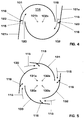
- Fig. 2 shows a schematic view of the burner according to Fig. 1, here in particular the flushing of a centrally arranged fuel nozzle 103 and the effect of fuel injectors 170 is pointed out.
- the mode of action the remaining main components of the burner, namely swirl generator 100 and transition piece 200 are closer under the following figures described.
- the fuel nozzle 103 is spaced with a ring 190 encased in which a number of circumferentially bored holes 161 through which an amount of air 160 is placed in an annular chamber 180 flows and carries out the flushing of the fuel lance there.
- These holes 161 are slanted forward so that it is appropriate axial component arises on the burner axis 60.
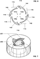
- the first part of the burner according to FIG. 1 forms the swirl generator 100 shown in FIG. 3. It consists of two hollow, conical partial bodies 101, 102, which are nested one inside the other.
- the number of conical partial bodies can of course be greater than two, as shown in FIGS. 5 and 6; This depends on the operating mode of the entire burner, as will be explained in more detail below. In certain operating constellations, it is not excluded to provide a swirl generator consisting of a single spiral.
- the offset of the respective central axis or longitudinal symmetry axes 101b, 102b (see FIG. 4) of the conical partial bodies 101, 102 to one another creates a tangential channel, ie an air inlet slot 119, 120 (see FIG.
- the conical shape of the partial bodies 101, 102 shown in the flow direction has a specific fixed angle.
- the partial bodies 101, 102 can have an increasing or decreasing cone inclination in the direction of flow, similar to a trumpet or. Tulip.
- the last two forms are not included in the drawing, since they can be easily understood by a person skilled in the art.
- the two conical partial bodies 101, 102 each have a cylindrical, ring-shaped initial part 101a.
- the fuel nozzle 103 already mentioned under FIG. 2 is accommodated in the region of this cylindrical starting part and is preferably operated with a liquid fuel 112.
- the injection 104 of this fuel 112 coincides approximately with the narrowest cross section of the conical cavity 114 formed by the conical partial bodies 101, 102.
- the injection capacity and the type of this fuel nozzle 103 depend on the specified parameters of the respective burner.
- the tapered partial bodies 101, 102 further each have a fuel line 108, 109, which are arranged along the tangential air inlet slots 119, 120 and are provided with injection openings 117, through which a gaseous fuel 113 is preferably injected into the combustion air 115 flowing through there, such as arrows 116 symbolize this.
- These fuel lines 108, 109 are preferably arranged at the latest at the end of the tangential inflow, before entering the cone cavity 114, in order to obtain an optimal air / fuel mixture.
- the fuel 112 brought up through the fuel nozzle 103 is normally a liquid fuel, and it is readily possible to form a mixture with another medium, for example with a recirculated flue gas.
- This fuel 112 is injected into the cone cavity 114 at a preferably very acute angle.
- a conical fuel spray 105 thus forms from the fuel nozzle 103 and is enclosed and broken down by the rotating combustion air 115 flowing in tangentially.
- the concentration of the injected fuel 112 is then continuously reduced in the axial direction by the inflowing combustion air 115 to mix in the direction of evaporation. If a gaseous fuel 113 is introduced via the opening nozzles 117, the fuel / air mixture is formed directly at the end of the air inlet slots 119, 120.
- combustion air 115 is additionally preheated or, for example, enriched with a recirculated flue gas or exhaust gas, this provides lasting support the evaporation of the liquid fuel 112 before this mixture flows into the downstream stage, here in the transition piece 200 (see FIGS. 1 and 7).
- liquid fuels should be supplied via lines 108, 109.
- a reduction in the size of the tangential air inlet slots 119, 120 already favors the faster formation of a backflow zone in the region of the swirl generator.
- the axial speed within the swirl generator 100 can be increased or stabilized by a corresponding supply of an air quantity described in more detail in FIG. 2 (item 160).
- a corresponding swirl generation in operative connection with the downstream transition piece 200 prevents the formation of flow separations within the mixing tube downstream of the swirl generator 100.
- the design of the swirl generator 100 is furthermore particularly suitable for changing the size of the tangential air inlet slots 119, 120, with which a relatively large operational bandwidth can be recorded without changing the overall length of the swirl generator 100.
- the partial bodies 101, 102 can also be displaced relative to one another in another plane, as a result of which an overlap thereof can even be provided. It is also possible to interleave the partial bodies 101, 102 in a spiral manner by counter-rotating movement. It is thus possible to vary the shape, the size and the configuration of the tangential air inlet slots 119, 120 as desired, with which the swirl generator 100 can be used universally without changing its overall length.
- the swirl generator 100 now consists of four partial bodies 130, 131, 132, 133 is constructed.
- the associated longitudinal symmetry axes for each sub-body are marked with the letter a. To this Configuration is to be said that it is due to the lower generated with it Twist strength and in cooperation with a correspondingly enlarged Slot width is best suited, the bursting of the vortex flow on the downstream side to prevent the swirl generator in the mixing tube, thus causing the mixing tube to can fulfill the intended role.
- FIG. 6 differs from FIG. 5 in that the partial bodies 140 here 141, 142, 143 have a blade profile shape which is used to provide a certain Flow is provided. Otherwise, the mode of operation of the swirl generator stayed the same.
- the admixture of fuel 116 in the combustion air flow 115 happens from inside the blade profiles, i.e. the fuel line 108 is now integrated in the individual blades.
- the transition geometry is corresponding for a swirl generator 100 with four partial bodies 5 or 6, built. Accordingly, the transition geometry as a natural extension of the upstream partial bodies, four transition channels 201 on, whereby the conical quarter area of said partial body is extended until it cuts the wall of the mixing tube.
- the same considerations also apply if the swirl generator is based on a principle other than the one below Fig. 3 described, is constructed.
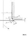
- the down in the direction of flow running surface of the individual transition channels 201 has a flow direction spiral shape, which has a crescent shape Course describes, corresponding to the fact that the flow cross-section is present of the transition piece 200 flared in the flow direction.
- the flow cross section of the tube 20 receives one in this area Transition radius R, the size of which basically depends on the flow within of the tube 20 depends.
- This radius R is chosen so that the Applies flow to the wall and so the swirl number increases sharply.
- the size of the radius R can be defined so that it is> 10% of the inside diameter d of the tube is 20.
- the backflow bladder 50 increases enormously.
- This radius R runs to the exit plane of the tube 20, the angle ⁇ between the beginning and end of curvature is ⁇ 90 °.
Landscapes
- Engineering & Computer Science (AREA)
- Chemical & Material Sciences (AREA)
- Combustion & Propulsion (AREA)
- Mechanical Engineering (AREA)
- General Engineering & Computer Science (AREA)
- Gas Burners (AREA)
Abstract
Description
- Fig. 1
- einen als Vormischbrenner ausgelegten Brenner mit einer Mischstrecke stromab eines Drallerzeugers sowie mit Pilotbrennern,
- Fig. 2
- eine schematische Darstellung des Brenners gemäss Fig. 1 mit Disposition der zusätzlichen Brennstoff-Injektoren,
- Fig. 3
- einen aus mehreren Schalen bestehenden Drallerzeuger in perspektivischer Darstellung, entsprechend aufgeschnitten,
- Fig. 4
- einen Querschnitt durch einen zweischaligen Drallerzeuger,
- Fig. 5
- einen Querschnitt durch einen vierschaligen Drallerzeuger,
- Fig. 6
- eine Ansicht durch einen Drallerzeuger, dessen Schalen schaufelförmig profiliert sind,
- Fig. 7
- eine Ausgestaltung der Uebergangsgeometrie zwischen Drallerzeuger und Mischstrecke und
- Fig. 8
- eine Abrisskante zur räumlichen Stabilisierung der Rückströmzone.
Konzentrisch zum Mischrohr 20, im Bereich seines Auslaufes, wird ein Pilotbrennersystem 300 vorgesehen. Dieses besteht aus einer inneren Ringkammer 301, in welche ein Brennstoff, vorzugsweise ein gasförmiger Brennstoff 303 einströmt. Nebengeordnet zu dieser inneren Ringkammer 301 ist eine zweite Ringkammer 302 disponiert, in welche eine Luftmenge 304 einströmt. Beide Ringkammern 301, 302 weisen individuell gestaltete Durchgangsöffnungen auf, dergestalt, dass die einzelnen Medien 303, 304 funktionsbedingt in eine gemeinsame nachgeschaltete Ringkammer 308 strömen. Die Ueberleitung des gasförmigen Brennstoffes 303 von der Ringkammer 301 in die nachgeschaltete Ringkammer 308 wird durch eine Anzahl in Umfangsrichtung angeordneter Oeffnungen 309 bewerkstelligt. Die Durchgangsgeometrie dieser Oeffnungen 309 ist so gestaltet, dass der gasförmige Brennstoff 303 mit einem grossen Vermischungspotential in die nachgeschaltete Ringkammer 308 einströmt. Die andere Ringkammer 302 schliesst mit einer gelochten Platte 305 ab, wobei die hier vorgesehenen Bohrungen 310 so gestaltet sind, dass die dort durchströmende Luftmenge 304 eine Prallkühlung auf die Bodenplatte 307 der nachgeschalteten Ringkammer 308. Diese Bodenplatte hat die Funktion eines Hitzeschutzbleches gegenüber der kalorischen Belastung aus dem Brennraum 30, so dass diese Prallkühlung hier äusserst effizient ausfallen muss.
Diese Brennstoffleitungen 108, 109 sind vorzugsweise spätestens am Ende der tangentialen Einströmung, vor Eintritt in den Kegelhohlraum 114, angeordnet, dies um eine optimale Luft/Brennstoff-Mischung zu erhalten. Bei dem durch die Brennstoffdüse 103 herangeführten Brennstoff 112 handelt es sich, wie erwähnt, im Normalfall um einen flüssigen Brennstoff, wobei eine Gemischbildung mit einem anderen Medium, beispielsweise mit einem rückgeführten Rauchgas, ohne weiteres möglich ist. Dieser Brennstoff 112 wird unter einem vorzugsweise sehr spitzen Winkel in den Kegelhohlraum 114 eingedüst. Aus der Brennstoffdüse 103 bildet sich sonach ein kegeliges Brennstoffspray 105, das von der tangential einströmenden rotierenden Verbrennungsluft 115 umschlossen und abgebaut wird.
In axialer Richtung wird sodann die Konzentration des eingedüsten Brennstoffes 112 fortlaufend durch die einströmenden Verbrennungsluft 115 zu einer Vermischung Richtung Verdampfung abgebaut. Wird ein gasförmiger Brennstoff 113 über die Oeffnungsdüsen 117 eingebracht, geschieht die Bildung des Brennstoff/Luft-Gemisches direkt am Ende der Lufteintrittsschlitze 119, 120. Ist die Verbrennungsluft 115 zusätzlich vorgeheizt, oder beispielsweise mit einem rückgeführten Rauchgas oder Abgas angereichert, so unterstützt dies nachhaltig die Verdampfung des flüssigen Brennstoffes 112, bevor dieses Gemisch in die nachgeschaltete Stufe strömt, hier in das Uebergangsstück 200 (Vgl. Fig. 1 und 7). Die gleichen Ueberlegungen gelten auch, wenn über die Leitungen 108, 109 flüssige Brennstoffe zugeführt werden sollten. Bei der Gestaltung der kegeligen Teilkörper 101, 102 hinsichtlich des Kegelwinkels und der Breite der tangentialen Lufteintrittsschlitze 119, 120 sind an sich enge Grenzen einzuhalten, damit sich das gewünschte Strömungsfeld der Verbrennungsluft 115 am Ausgang des Drallerzeugers 100 einstellen kann. Allgemein ist zu sagen, dass eine Verkleinerung der tangentialen Lufteintrittsschlitze 119, 120 die schnellere Bildung einer Rückströmzone bereits im Bereich des Drallerzeugers begünstigt. Die Axialgeschwindigkeit innerhalb des Drallerzeugers 100 lässt sich durch eine entsprechende unter Fig. 2 (Pos. 160) näher beschriebene Zuführung einer Luftmenge erhöhen bzw. stabilisieren. Eine entsprechende Drallerzeugung in Wirkverbindung mit dem nachgeschalteten Uebergangsstück 200 (Vgl. Fig. 1 und 7) verhindert die Bildung von Strömungsablösungen innerhalb des dem Drallerzeuger 100 nachgeschalteten Mischrohr. Die Konstruktion des Drallerzeugers 100 eignet sich des weiteren vorzüglich, die Grösse der tangentialen Lufteintrittsschlitze 119, 120 zu verändern, womit ohne Veränderung der Baulänge des Drallerzeugers 100 eine relativ grosse betriebliche Bandbreite erfasst werden kann. Selbstverständlich sind die Teilkörper 101, 102 auch in einer anderen Ebene zueinander verschiebbar, wodurch sogar eine Ueberlappung derselben vorgesehen werden kann. Es ist des weiteren möglich, die Teilkörper 101, 102 durch eine gegenläufig drehende Bewegung spiralartig ineinander zu verschachteln. Somit ist es möglich, die Form, die Grösse und die Konfiguration der tangentialen Lufteintrittsschlitze 119, 120 beliebig zu variieren, womit der Drallerzeuger 100 ohne Veränderung seiner Baulänge universell einsetzbar ist.
- 10
- Buchsenring
- 20
- Mischrohr, Teil der Mischstrecke 220
- 21
- Bohrungen, Oeffnungen
- 30
- Brennkammer, Brennraum
- 40
- Strömung, Rohrströmung im Mischrohr, Hauptströmung
- 50
- Rückströmzone, Rückströmblase
- 60
- Brennerachse
- 100
- Drallerzeuger
- 101, 102
- Kegelförmige Teilkörper
- 101a
- Ringförmiger Anfangsteil
- 101b, 102b
- Längssymmetrieachsen
- 103
- Brennstoffdüse
- 104
- Brennstoffeindüsung
- 105
- Brennstoffspray (Brennstoffeindüsungsprofil)
- 108, 109
- Brennstoffleitungen
- 112
- Flüssiger Brennstoff
- 113
- Gasförmiger Brennstoff
- 114
- Kegelhohlraum
- 115
- Verbrennungsluft (Verbrennungsluftstrom)
- 116
- Brennstoff-Eindüsung aus den Leitungen 108, 109
- 117
- Brennstoffdüsen
- 119, 120
- Tangentiale Lufteintrittsschlitze
- 121a, 121b
- Leitbleche
- 123
- Drehpunkt der Leitbleche
- 130, 131, 132, 133
- Teilkörper
- 131a, 131a, 132a, 133a
- Längssymmetrieachsen
- 140, 141, 142, 143
- Schaufelprofilförmige Teilkörper
- 140a, 141a, 142a, 143a
- Längssymmetrieachsen
- 150
- Brennstoffkonzentration
- 160
- Luftmenge, Mischluft
- 161
- Bohrungen, Oeffnungen
- 170
- Brennstoff-Injektoren
- 180
- Ringförmige Luftkammer
- 190
- Ring
- 200
- Uebergangsstück, Teil der Mischstrecke 220
- 201
- Uebergangskanäle
- 220
- Mischstrecke
- 300
- Pilotbrennersystem
- 301
- Innere Ringkammer
- 302
- Nebengeordnete Ringkammer
- 303
- Gasförmiger Brennstoff
- 304
- Luftmenge
- 305
- Gelochte Platte
- 306
- Bohrungen in den Brennraum, Pilotbrenner
- 307
- Hitzeschutzblech
- 308
- Nachgeschaltete Ringkammer
- 309
- Oeffnungen der inneren Ringkammer
- 310
- Löcher für Prallkühlung des Hitzeschutzbleches
Claims (18)
- Brenner zum Betrieb eines Wärmeerzeugers, wobei der Brenner im wesentlichen aus einem Drallerzeuger für einen Verbrennungsluftstrom, aus Mitteln zur Eindüsung mindestens eines Brennstoffes in den Verbrennungsluftstrom besteht, wobei stromab des Drallerzeugers eine Mischstrecke angeordnet ist, welche innerhalb eines ersten Streckenteils in Strömungsrichtung eine Anzahl Uebergangskanäle zur Ueberführung einer im Drallerzeuger gebildeten Strömung in ein stromab dieser Uebergangskanäle nachgeschaltetes Mischrohr aufweist, dadurch gekennzeichnet, dass im unteren Bereich des Mischrohres (20) mit Wirkung in einen dem Mischrohr (20) nachgeschalteten Brennraum (30) ein Pilotbrennersystem (300) angeordnet ist, welches aus mindestens zwei medienführenden Kammern (301, 302) und aus einer weiteren gemeinsamen nachgeschalteten Kammer (308) besteht, dass in dieser nachgeschalteten Kammer (308) die Medien (303, 304) aus den beiden anderen Kammern (301, 302) mischbar sind, und dass die nachgeschaltete Kammer (308) Mittel zur Bildung von in den Brennraum (30) wirkenden vom Gemisch der beiden Medien (303, 304) betreibbaren Pilotbrennern (306) aufweist.
- Brenner nach Anspruch 1, dadurch gekennzeichnet, dass durch die medienführenden Kammern (301, 303) ringförmig und nebengeordnet ausgebildet sind, dass durch die erste Ringkammer (301) ein gasförmiger Brennstoff (303) und durch die zweite Ringkammer (302) eine Luftmenge (304) strömen, dass in der zweiten Ringkammer (302) Mittel (305) eingebaut sind, durch welche die dort strömende Luft (304) eine Prallkühlung auf ein endseitig des Pilotbrennersystems (300) angeordnetes Hitzeschutzblech (307) bewerkstelligt.
- Brenner nach Anspruch 2, dadurch gekennzeichnet, dass das Mittel zur Bildung der Prallkühlung eine in der nebengeordneten Ringkammer (302) bodenbildende gelochte Platte (305) ist.
- Brenner nach Anspruch 1, dadurch gekennzeichnet, dass die Mittel aus einem kopfseitig des Drallerzeugers (100) und in Wirkverbindung mit einer Brennstoffdüse (103) angeordneten Ring (190) besteht, dass dier Ring (190) eine Anzahl in Umfangsrichtung angeordneter Bohrungen (161) aufweist, und dass in eine durch die Bohrungen (161) strömende Luftmenge (160) ein Brennstoff (170) eindüsbar ist.
- Brenner nach Anspruch 4, dadurch gekennzeichnet, dass die Bohrungen (161) schräg nach vorne gerichtet sind.
- Brenner nach Anspruch 4, dadurch gekennzeichnet, dass die Brennstoffdüse (103) von einer rinförmiger Luftkammer (180) umgeben ist.
- Brenner nach Anspruch 1, dadurch gekennzeichnet, dass die Brennerfront des Mischrohres (20) zur nachgeschalteten Brennraum (30) mit einer Abrisskante (A) ausgebildet ist.
- Brenner nach Anspruch 1, dadurch gekennzeichnet, dass die Anzahl der Uebergangskanäle (201) in der Mischstrecke (220) der Anzahl der vom Drallerzeuger (100) gebildeten Teilströme entspricht.
- Brenner nach Anspruch 1, dadurch gekennzeichnet, dass das den Uebergangskanälen (201) nachgeschaltete Mischrohr (20) in Strömungs- und Umfangsrichtung mit Oeffnungen (21) zur Eindüsung eines Luftstromes ins Innere des Mischrohres (20) versehen ist.
- Brenner nach Anspruch 9, dadurch gekennzeichnet, dass die Oeffnungen (21) unter einem spitzen Winkel gegenüber der Brennerachse (60) des Mischrohres (20) verlaufen.
- Brenner nach Anspruch 1, dadurch gekennzeichnet, dass der Durchflussquerschnitt des Mischrohres (20) stromab der Uebergangskanäle (201) kleiner, gleich gross oder grösser als der Querschnitt der im Drallerzeuger (100, 100a) gebildeten Strömung (40) ist.
- Brenner nach Anspruch 1, dadurch gekennzeichnet, dass stromab der Mischstrecke (220) eine Brennkammer (30) angeordnet ist, dass zwischen der Mischstrecke (220) und der Brennkammer (30) ein Querschnittssprung vorhanden ist, der den anfänglichen Strömungsquerschnitt der Brennkammer (30) induziert, und dass im Bereich dieses Querschnittssprunges eine Rückströmzone (50) wirkbar ist.
- Brenner nach Anspruch 1, dadurch gekennzeichnet, dass stromauf der Brennerfront (70) ein Diffusor und/oder eine Venturistrecke vorhanden ist.
- Brenner nach Anspruch 1, dadurch gekennzeichnet, dass der Drallerzeuger (100) aus mindestens zwei hohlen, kegelförmigen, in Strömungsrichtung ineinandergeschachtelten Teilkörpern (101, 102; 130, 131, 132, 133; 140, 141, 142, 143) besteht, dass die jeweiligen Längssymmetrieachsen (101b, 102b; 130a, 131a, 132a, 133a; 140a, 141a, 142a, 143a) dieser Teilkörper gegeneinander versetzt verlaufen, dergestalt, dass die benachbarten Wandungen der Teilkörper in deren Längserstreckung tangentiale Kanäle (119, 120) für einen Verbrennungsluftstromes (115) bilden, und dass im von den Teilkörpern gebildeten Innenraum (114) mindestens eine Brennstoffdüse (103 wirkbar ist.
- Brenner nach Anspruch 14, dadurch gekennzeichnet, dass im Bereich der tangentialen Kanäle (119, 120) in deren Längserstreckung weitere Brennstoffdüsen (117) angeordnet sind.
- Brenner nach Anspruch 14, dadurch gekennzeichnet, dass die Teilkörper (140, 141, 142, 143) im Querschnitt eine schaufelförmige Profilierung aufweisen.
- Brenner nach Anspruch 14, dadurch gekennzeichnet, dass die Teilkörper in Strömungsrichtung einen festen Kegelwinkel, oder eine zunehmende Kegelneigung, oder eine abnehmende Kegelneigung aufweisen.
- Brenner nach Anspruch 14, dadurch gekennzeichnet, dass die Teilkörper spiralförmig ineinandergeschachtelt sind.
Priority Applications (3)
| Application Number | Priority Date | Filing Date | Title |
|---|---|---|---|
| DE59709061T DE59709061D1 (de) | 1997-10-14 | 1997-10-14 | Brenner für den Betrieb eines Wärmeerzeugers |
| EP97810773A EP0909921B1 (de) | 1997-10-14 | 1997-10-14 | Brenner für den Betrieb eines Wärmeerzeugers |
| US09/169,140 US5954495A (en) | 1997-10-14 | 1998-10-09 | Burner for operating a heat generator |
Applications Claiming Priority (1)
| Application Number | Priority Date | Filing Date | Title |
|---|---|---|---|
| EP97810773A EP0909921B1 (de) | 1997-10-14 | 1997-10-14 | Brenner für den Betrieb eines Wärmeerzeugers |
Publications (2)
| Publication Number | Publication Date |
|---|---|
| EP0909921A1 true EP0909921A1 (de) | 1999-04-21 |
| EP0909921B1 EP0909921B1 (de) | 2003-01-02 |
Family
ID=8230430
Family Applications (1)
| Application Number | Title | Priority Date | Filing Date |
|---|---|---|---|
| EP97810773A Expired - Lifetime EP0909921B1 (de) | 1997-10-14 | 1997-10-14 | Brenner für den Betrieb eines Wärmeerzeugers |
Country Status (3)
| Country | Link |
|---|---|
| US (1) | US5954495A (de) |
| EP (1) | EP0909921B1 (de) |
| DE (1) | DE59709061D1 (de) |
Cited By (2)
| Publication number | Priority date | Publication date | Assignee | Title |
|---|---|---|---|---|
| EP1213536A3 (de) * | 2000-12-11 | 2002-10-23 | ALSTOM Power N.V. | Vormischbrenneranordnung mit katalytischem Pilotbrenner |
| DE102008000050A1 (de) * | 2007-08-07 | 2009-02-12 | Alstom Technology Ltd. | Brenner für eine Brennkammer einer Turbogruppe |
Families Citing this family (12)
| Publication number | Priority date | Publication date | Assignee | Title |
|---|---|---|---|---|
| ATE237101T1 (de) * | 1998-01-23 | 2003-04-15 | Alstom Switzerland Ltd | Brenner für den betrieb eines wärmeerzeugers |
| EP0987493B1 (de) * | 1998-09-16 | 2003-08-06 | Abb Research Ltd. | Brenner für einen Wärmeerzeuger |
| EP0994300B1 (de) * | 1998-10-14 | 2003-11-26 | ALSTOM (Switzerland) Ltd | Brenner für den Betrieb eines Wärmeerzeugers |
| AU2003226079A1 (en) * | 2002-04-09 | 2003-10-27 | Sapias, Inc. | Asset management platform |
| EP1389713A1 (de) * | 2002-08-12 | 2004-02-18 | ALSTOM (Switzerland) Ltd | Stromabwärtiger Pilotringbrenner für Vormischbrenner |
| US6623267B1 (en) * | 2002-12-31 | 2003-09-23 | Tibbs M. Golladay, Jr. | Industrial burner |
| US20040202977A1 (en) * | 2003-04-08 | 2004-10-14 | Ken Walkup | Low NOx burner |
| US7303388B2 (en) * | 2004-07-01 | 2007-12-04 | Air Products And Chemicals, Inc. | Staged combustion system with ignition-assisted fuel lances |
| WO2006069861A1 (de) * | 2004-12-23 | 2006-07-06 | Alstom Technology Ltd | Vormischbrenner mit mischstrecke |
| EP2110601A1 (de) * | 2008-04-15 | 2009-10-21 | Siemens Aktiengesellschaft | Brenner |
| EP2650612A1 (de) * | 2012-04-10 | 2013-10-16 | Siemens Aktiengesellschaft | Brenner |
| US9400104B2 (en) | 2012-09-28 | 2016-07-26 | United Technologies Corporation | Flow modifier for combustor fuel nozzle tip |
Citations (8)
| Publication number | Priority date | Publication date | Assignee | Title |
|---|---|---|---|---|
| DE3033988A1 (de) * | 1980-09-10 | 1982-03-18 | Karl-Friedrich Dipl.-Wirtsch.-Ing. Dipl.-Ing. 5650 Solingen Schmid | Gasbrenner zur erzeugung von heizgasen mit breiter temperaturvarianz |
| EP0376259A2 (de) * | 1988-12-26 | 1990-07-04 | Hitachi, Ltd. | Kessel mit vermindertem NOx-Ausstoss |
| JPH0682084A (ja) * | 1992-09-02 | 1994-03-22 | Daikin Ind Ltd | 空気調和装置の運転制御装置 |
| EP0670456A1 (de) * | 1994-03-04 | 1995-09-06 | NUOVOPIGNONE INDUSTRIE MECCANICHE E FONDERIA S.p.A. | Verbesserte Verbrennungsanlage mit niedriger Schadstoffemission für Gasturbinen |
| JPH0882419A (ja) * | 1994-09-14 | 1996-03-26 | Hitachi Ltd | ガスタービン用燃焼器 |
| EP0780629A2 (de) | 1995-12-21 | 1997-06-25 | ABB Research Ltd. | Brenner für einen Wärmeerzeuger |
| EP0780630A2 (de) * | 1995-12-21 | 1997-06-25 | Abb Research Ltd. | Brenner für einen Wärmeerzeuger |
| EP0797051A2 (de) * | 1996-03-20 | 1997-09-24 | Abb Research Ltd. | Brenner für einen Wärmeerzeuger |
Family Cites Families (2)
| Publication number | Priority date | Publication date | Assignee | Title |
|---|---|---|---|---|
| DE4411623A1 (de) * | 1994-04-02 | 1995-10-05 | Abb Management Ag | Vormischbrenner |
| DE4416650A1 (de) * | 1994-05-11 | 1995-11-16 | Abb Management Ag | Verbrennungsverfahren für atmosphärische Feuerungsanlagen |
-
1997
- 1997-10-14 EP EP97810773A patent/EP0909921B1/de not_active Expired - Lifetime
- 1997-10-14 DE DE59709061T patent/DE59709061D1/de not_active Expired - Lifetime
-
1998
- 1998-10-09 US US09/169,140 patent/US5954495A/en not_active Expired - Fee Related
Patent Citations (8)
| Publication number | Priority date | Publication date | Assignee | Title |
|---|---|---|---|---|
| DE3033988A1 (de) * | 1980-09-10 | 1982-03-18 | Karl-Friedrich Dipl.-Wirtsch.-Ing. Dipl.-Ing. 5650 Solingen Schmid | Gasbrenner zur erzeugung von heizgasen mit breiter temperaturvarianz |
| EP0376259A2 (de) * | 1988-12-26 | 1990-07-04 | Hitachi, Ltd. | Kessel mit vermindertem NOx-Ausstoss |
| JPH0682084A (ja) * | 1992-09-02 | 1994-03-22 | Daikin Ind Ltd | 空気調和装置の運転制御装置 |
| EP0670456A1 (de) * | 1994-03-04 | 1995-09-06 | NUOVOPIGNONE INDUSTRIE MECCANICHE E FONDERIA S.p.A. | Verbesserte Verbrennungsanlage mit niedriger Schadstoffemission für Gasturbinen |
| JPH0882419A (ja) * | 1994-09-14 | 1996-03-26 | Hitachi Ltd | ガスタービン用燃焼器 |
| EP0780629A2 (de) | 1995-12-21 | 1997-06-25 | ABB Research Ltd. | Brenner für einen Wärmeerzeuger |
| EP0780630A2 (de) * | 1995-12-21 | 1997-06-25 | Abb Research Ltd. | Brenner für einen Wärmeerzeuger |
| EP0797051A2 (de) * | 1996-03-20 | 1997-09-24 | Abb Research Ltd. | Brenner für einen Wärmeerzeuger |
Non-Patent Citations (2)
| Title |
|---|
| PATENT ABSTRACTS OF JAPAN vol. 18, no. 341 (M - 1629) 28 June 1994 (1994-06-28) * |
| PATENT ABSTRACTS OF JAPAN vol. 96, no. 7 31 July 1996 (1996-07-31) * |
Cited By (3)
| Publication number | Priority date | Publication date | Assignee | Title |
|---|---|---|---|---|
| EP1213536A3 (de) * | 2000-12-11 | 2002-10-23 | ALSTOM Power N.V. | Vormischbrenneranordnung mit katalytischem Pilotbrenner |
| US6679061B2 (en) | 2000-12-11 | 2004-01-20 | Alstom Technology Ltd. | Premix burner arrangement for operating a combustion chamber |
| DE102008000050A1 (de) * | 2007-08-07 | 2009-02-12 | Alstom Technology Ltd. | Brenner für eine Brennkammer einer Turbogruppe |
Also Published As
| Publication number | Publication date |
|---|---|
| DE59709061D1 (de) | 2003-02-06 |
| US5954495A (en) | 1999-09-21 |
| EP0909921B1 (de) | 2003-01-02 |
Similar Documents
| Publication | Publication Date | Title |
|---|---|---|
| EP0780629B1 (de) | Brenner für einen Wärmeerzeuger | |
| EP0704657B1 (de) | Brenner | |
| EP0918191B1 (de) | Brenner für den Betrieb eines Wärmeerzeugers | |
| EP0918190A1 (de) | Brenner für den Betrieb eines Wärmeerzeugers | |
| EP0780630B1 (de) | Brenner für einen Wärmeerzeuger | |
| EP0899508B1 (de) | Brenner für einen Wärmeerzeuger | |
| EP0833105B1 (de) | Vormischbrenner | |
| DE19757189B4 (de) | Verfahren zum Betrieb eines Brenners eines Wärmeerzeugers | |
| EP0718561B1 (de) | Brennkammer | |
| EP0797051B1 (de) | Brenner für einen Wärmeerzeuger | |
| EP0931980B1 (de) | Brenner für den Betrieb eines Wärmeerzeugers | |
| EP0694740A2 (de) | Brennkammer | |
| EP0777081B1 (de) | Vormischbrenner | |
| EP0987493B1 (de) | Brenner für einen Wärmeerzeuger | |
| EP0994300B1 (de) | Brenner für den Betrieb eines Wärmeerzeugers | |
| EP0909921B1 (de) | Brenner für den Betrieb eines Wärmeerzeugers | |
| EP0851172B1 (de) | Brenner und Verfahren zum Betrieb einer Brennkammer mit einem flüssigen und/oder gasförmigen Brennstoff | |
| EP0916894B1 (de) | Brenner für den Betrieb eines Wärmeerzeugers | |
| EP0751351A1 (de) | Brennkammer | |
| EP0903540B1 (de) | Brenner für den Betrieb eines Wärmeerzeugers | |
| EP0919768B1 (de) | Brenner zum Betrieb eines Wärmeerzeugers | |
| EP0833104B1 (de) | Brenner zum Betrieb einer Brennkammer | |
| DE19537636B4 (de) | Kraftwerksanlage | |
| EP0913630B1 (de) | Brenner für den Betrieb eines Wärmeerzeugers | |
| DE19914666A1 (de) | Brenner für einen Wärmeerzeuger |
Legal Events
| Date | Code | Title | Description |
|---|---|---|---|
| PUAI | Public reference made under article 153(3) epc to a published international application that has entered the european phase |
Free format text: ORIGINAL CODE: 0009012 |
|
| AK | Designated contracting states |
Kind code of ref document: A1 Designated state(s): CH DE FR GB LI NL SE |
|
| 17P | Request for examination filed |
Effective date: 19990906 |
|
| AKX | Designation fees paid |
Free format text: AT |
|
| REG | Reference to a national code |
Ref country code: DE Ref legal event code: 8566 |
|
| RBV | Designated contracting states (corrected) |
Designated state(s): CH DE FR GB LI NL SE |
|
| GRAG | Despatch of communication of intention to grant |
Free format text: ORIGINAL CODE: EPIDOS AGRA |
|
| 17Q | First examination report despatched |
Effective date: 20020429 |
|
| GRAG | Despatch of communication of intention to grant |
Free format text: ORIGINAL CODE: EPIDOS AGRA |
|
| GRAH | Despatch of communication of intention to grant a patent |
Free format text: ORIGINAL CODE: EPIDOS IGRA |
|
| RAP1 | Party data changed (applicant data changed or rights of an application transferred) |
Owner name: ALSTOM |
|
| GRAH | Despatch of communication of intention to grant a patent |
Free format text: ORIGINAL CODE: EPIDOS IGRA |
|
| GRAA | (expected) grant |
Free format text: ORIGINAL CODE: 0009210 |
|
| AK | Designated contracting states |
Kind code of ref document: B1 Designated state(s): CH DE FR GB LI NL SE |
|
| PG25 | Lapsed in a contracting state [announced via postgrant information from national office to epo] |
Ref country code: NL Free format text: LAPSE BECAUSE OF FAILURE TO SUBMIT A TRANSLATION OF THE DESCRIPTION OR TO PAY THE FEE WITHIN THE PRESCRIBED TIME-LIMIT Effective date: 20030102 |
|
| REG | Reference to a national code |
Ref country code: GB Ref legal event code: FG4D Free format text: 20030102:NOT ENGLISH |
|
| REG | Reference to a national code |
Ref country code: CH Ref legal event code: EP |
|
| REF | Corresponds to: |
Ref document number: 59709061 Country of ref document: DE Date of ref document: 20030206 Kind code of ref document: P |
|
| REG | Reference to a national code |
Ref country code: SE Ref legal event code: TRGR |
|
| GBT | Gb: translation of ep patent filed (gb section 77(6)(a)/1977) |
Effective date: 20030507 |
|
| ET | Fr: translation filed | ||
| PG25 | Lapsed in a contracting state [announced via postgrant information from national office to epo] |
Ref country code: LI Free format text: LAPSE BECAUSE OF NON-PAYMENT OF DUE FEES Effective date: 20031031 Ref country code: CH Free format text: LAPSE BECAUSE OF NON-PAYMENT OF DUE FEES Effective date: 20031031 |
|
| PLBE | No opposition filed within time limit |
Free format text: ORIGINAL CODE: 0009261 |
|
| STAA | Information on the status of an ep patent application or granted ep patent |
Free format text: STATUS: NO OPPOSITION FILED WITHIN TIME LIMIT |
|
| 26N | No opposition filed |
Effective date: 20031003 |
|
| REG | Reference to a national code |
Ref country code: CH Ref legal event code: PL |
|
| REG | Reference to a national code |
Ref country code: GB Ref legal event code: 732E Free format text: REGISTERED BETWEEN 20110428 AND 20110504 |
|
| REG | Reference to a national code |
Ref country code: FR Ref legal event code: TP |
|
| REG | Reference to a national code |
Ref country code: FR Ref legal event code: PLFP Year of fee payment: 19 |
|
| REG | Reference to a national code |
Ref country code: FR Ref legal event code: PLFP Year of fee payment: 20 |
|
| PGFP | Annual fee paid to national office [announced via postgrant information from national office to epo] |
Ref country code: FR Payment date: 20161028 Year of fee payment: 20 Ref country code: GB Payment date: 20161013 Year of fee payment: 20 |
|
| PGFP | Annual fee paid to national office [announced via postgrant information from national office to epo] |
Ref country code: SE Payment date: 20161011 Year of fee payment: 20 |
|
| PGFP | Annual fee paid to national office [announced via postgrant information from national office to epo] |
Ref country code: DE Payment date: 20161220 Year of fee payment: 20 |
|
| REG | Reference to a national code |
Ref country code: DE Ref legal event code: R071 Ref document number: 59709061 Country of ref document: DE |
|
| REG | Reference to a national code |
Ref country code: GB Ref legal event code: PE20 Expiry date: 20171013 |
|
| PG25 | Lapsed in a contracting state [announced via postgrant information from national office to epo] |
Ref country code: GB Free format text: LAPSE BECAUSE OF EXPIRATION OF PROTECTION Effective date: 20171013 |