EP0909951A1 - Méthode et dispositif pour la détermination quantitiv de hydrogène lié et/ou libre - Google Patents
Méthode et dispositif pour la détermination quantitiv de hydrogène lié et/ou libre Download PDFInfo
- Publication number
- EP0909951A1 EP0909951A1 EP97117290A EP97117290A EP0909951A1 EP 0909951 A1 EP0909951 A1 EP 0909951A1 EP 97117290 A EP97117290 A EP 97117290A EP 97117290 A EP97117290 A EP 97117290A EP 0909951 A1 EP0909951 A1 EP 0909951A1
- Authority
- EP
- European Patent Office
- Prior art keywords
- membrane
- hydrogen
- gas stream
- gas
- catalyst
- Prior art date
- Legal status (The legal status is an assumption and is not a legal conclusion. Google has not performed a legal analysis and makes no representation as to the accuracy of the status listed.)
- Granted
Links
- 239000001257 hydrogen Substances 0.000 title claims abstract description 115
- 229910052739 hydrogen Inorganic materials 0.000 title claims abstract description 115
- UFHFLCQGNIYNRP-UHFFFAOYSA-N Hydrogen Chemical compound [H][H] UFHFLCQGNIYNRP-UHFFFAOYSA-N 0.000 title claims abstract description 111
- 238000000034 method Methods 0.000 title claims abstract description 33
- 239000007789 gas Substances 0.000 claims abstract description 104
- 239000012528 membrane Substances 0.000 claims abstract description 78
- QGZKDVFQNNGYKY-UHFFFAOYSA-N Ammonia Chemical compound N QGZKDVFQNNGYKY-UHFFFAOYSA-N 0.000 claims abstract description 48
- 238000010438 heat treatment Methods 0.000 claims abstract description 25
- 229910021529 ammonia Inorganic materials 0.000 claims abstract description 24
- 230000003197 catalytic effect Effects 0.000 claims abstract description 20
- 239000000203 mixture Substances 0.000 claims abstract description 13
- 230000008569 process Effects 0.000 claims abstract description 11
- 230000015572 biosynthetic process Effects 0.000 claims abstract description 6
- 229930195733 hydrocarbon Natural products 0.000 claims abstract description 5
- 150000002430 hydrocarbons Chemical class 0.000 claims abstract description 5
- 239000004215 Carbon black (E152) Substances 0.000 claims abstract 2
- 150000001875 compounds Chemical class 0.000 claims description 22
- 239000003054 catalyst Substances 0.000 claims description 21
- 238000011144 upstream manufacturing Methods 0.000 claims description 9
- PXHVJJICTQNCMI-UHFFFAOYSA-N Nickel Chemical compound [Ni] PXHVJJICTQNCMI-UHFFFAOYSA-N 0.000 claims description 8
- 238000003776 cleavage reaction Methods 0.000 claims description 8
- 230000007017 scission Effects 0.000 claims description 7
- 229910001316 Ag alloy Inorganic materials 0.000 claims description 5
- 150000002431 hydrogen Chemical class 0.000 claims description 5
- 239000000463 material Substances 0.000 claims description 5
- SWELZOZIOHGSPA-UHFFFAOYSA-N palladium silver Chemical compound [Pd].[Ag] SWELZOZIOHGSPA-UHFFFAOYSA-N 0.000 claims description 5
- 229910052759 nickel Inorganic materials 0.000 claims description 4
- 230000008859 change Effects 0.000 claims description 2
- 239000010970 precious metal Substances 0.000 claims description 2
- 229910000923 precious metal alloy Inorganic materials 0.000 claims description 2
- XLYOFNOQVPJJNP-UHFFFAOYSA-N water Substances O XLYOFNOQVPJJNP-UHFFFAOYSA-N 0.000 claims description 2
- 229910045601 alloy Inorganic materials 0.000 abstract description 2
- 239000000956 alloy Substances 0.000 abstract description 2
- 229910000510 noble metal Inorganic materials 0.000 abstract 1
- 238000005121 nitriding Methods 0.000 description 27
- IJGRMHOSHXDMSA-UHFFFAOYSA-N Atomic nitrogen Chemical compound N#N IJGRMHOSHXDMSA-UHFFFAOYSA-N 0.000 description 12
- 238000005259 measurement Methods 0.000 description 8
- 239000000523 sample Substances 0.000 description 7
- 229910052757 nitrogen Inorganic materials 0.000 description 6
- 238000006243 chemical reaction Methods 0.000 description 5
- 150000004767 nitrides Chemical class 0.000 description 4
- 230000008901 benefit Effects 0.000 description 3
- 229910052799 carbon Inorganic materials 0.000 description 3
- OKTJSMMVPCPJKN-UHFFFAOYSA-N Carbon Chemical compound [C] OKTJSMMVPCPJKN-UHFFFAOYSA-N 0.000 description 2
- 238000010521 absorption reaction Methods 0.000 description 2
- 238000004458 analytical method Methods 0.000 description 2
- QVGXLLKOCUKJST-UHFFFAOYSA-N atomic oxygen Chemical compound [O] QVGXLLKOCUKJST-UHFFFAOYSA-N 0.000 description 2
- 238000005553 drilling Methods 0.000 description 2
- 239000001301 oxygen Substances 0.000 description 2
- 229910052760 oxygen Inorganic materials 0.000 description 2
- 239000000376 reactant Substances 0.000 description 2
- 239000007784 solid electrolyte Substances 0.000 description 2
- VYZAMTAEIAYCRO-UHFFFAOYSA-N Chromium Chemical compound [Cr] VYZAMTAEIAYCRO-UHFFFAOYSA-N 0.000 description 1
- 229910000831 Steel Inorganic materials 0.000 description 1
- RTAQQCXQSZGOHL-UHFFFAOYSA-N Titanium Chemical compound [Ti] RTAQQCXQSZGOHL-UHFFFAOYSA-N 0.000 description 1
- 229910052782 aluminium Inorganic materials 0.000 description 1
- XAGFODPZIPBFFR-UHFFFAOYSA-N aluminium Chemical compound [Al] XAGFODPZIPBFFR-UHFFFAOYSA-N 0.000 description 1
- -1 carbon and nitrogen Chemical compound 0.000 description 1
- 239000000919 ceramic Substances 0.000 description 1
- 238000012512 characterization method Methods 0.000 description 1
- 239000011248 coating agent Substances 0.000 description 1
- 238000000576 coating method Methods 0.000 description 1
- 238000009833 condensation Methods 0.000 description 1
- 230000005494 condensation Effects 0.000 description 1
- 238000001816 cooling Methods 0.000 description 1
- 238000005260 corrosion Methods 0.000 description 1
- 230000007797 corrosion Effects 0.000 description 1
- 238000000354 decomposition reaction Methods 0.000 description 1
- 238000010586 diagram Methods 0.000 description 1
- 230000000694 effects Effects 0.000 description 1
- 230000004992 fission Effects 0.000 description 1
- 238000004868 gas analysis Methods 0.000 description 1
- 239000010410 layer Substances 0.000 description 1
- 230000000149 penetrating effect Effects 0.000 description 1
- 238000004886 process control Methods 0.000 description 1
- 238000010926 purge Methods 0.000 description 1
- 238000004445 quantitative analysis Methods 0.000 description 1
- 239000010453 quartz Substances 0.000 description 1
- VYPSYNLAJGMNEJ-UHFFFAOYSA-N silicon dioxide Inorganic materials O=[Si]=O VYPSYNLAJGMNEJ-UHFFFAOYSA-N 0.000 description 1
- 239000010959 steel Substances 0.000 description 1
- 239000000126 substance Substances 0.000 description 1
- 239000002344 surface layer Substances 0.000 description 1
- 239000010936 titanium Substances 0.000 description 1
- 229910052719 titanium Inorganic materials 0.000 description 1
- 230000007704 transition Effects 0.000 description 1
- 229910052720 vanadium Inorganic materials 0.000 description 1
- GPPXJZIENCGNKB-UHFFFAOYSA-N vanadium Chemical compound [V]#[V] GPPXJZIENCGNKB-UHFFFAOYSA-N 0.000 description 1
Images


Classifications
-
- G—PHYSICS
- G01—MEASURING; TESTING
- G01N—INVESTIGATING OR ANALYSING MATERIALS BY DETERMINING THEIR CHEMICAL OR PHYSICAL PROPERTIES
- G01N33/00—Investigating or analysing materials by specific methods not covered by groups G01N1/00 - G01N31/00
- G01N33/0004—Gaseous mixtures, e.g. polluted air
- G01N33/0009—General constructional details of gas analysers, e.g. portable test equipment
- G01N33/0027—General constructional details of gas analysers, e.g. portable test equipment concerning the detector
- G01N33/0036—General constructional details of gas analysers, e.g. portable test equipment concerning the detector specially adapted to detect a particular component
- G01N33/005—H2
Definitions
- the temperature of the membrane is defined in the Range from 300 to 1000 ° C, in ammonia-containing gas atmospheres preferably in the range of 400 to 650 ° C, set to depending of the material used for the membrane the respective specific genetics the catalytic cleavage reaction.
- the in ammonia-containing gas atmospheres Flow rate of the gas stream along the surface of the Membrane is at least 140 cm / min to have a catalytic effect Exclude membrane.
- a precious metal alloy is used as the material for the membrane, which can withstand temperatures up to can be loaded above 1,000 ° C.
- the gas stream is brought into contact with a catalyst prior to permeation of the hydrogen through the membrane, which causes a splitting of hydrogen-containing compounds in the gas stream to form additional hydrogen, and the change in the hydrogen partial pressure then measured as Measure used for the content of hydrogen-containing compounds in the gas stream.
- changes in the Temperature and / or the flow rate of the gas stream Surface of the membrane is temporarily made to act catalytically Determination of the content of a hydrogen-containing compound.
- the hydrogen partial pressure is expediently set via a first and second membrane measured, the on one of the two membranes Gas flow with hydrogen due to the catalytic splitting of hydrogen-containing compounds is enriched, so that a simultaneous Measurement of the content of hydrogen and hydrogen-containing compounds is possible, which is a continuous determination, for example, of Nitriding index allowed.
- An apparatus for performing the method preferably has one capillary-shaped, permselective surrounded by a tube Membrane on that in the axial direction in between its outer Shell surface and the inner surface of the tube formed by an annular gap Gas flow is flowing around, the interior of the membrane to one Pressure sensor can be connected.
- a device enables simple and inexpensive, that is, special practical determination of the content of free or in hydrogen-containing compounds bound hydrogen after the method according to the invention.
- the one formed between the membrane and the tube Annular gap allows the gas flow to be guided along the surface the membrane in such a way that there is no catalytic effect.
- the interior of the membrane can advantageously be evacuated in order to ensure that the pressure sensed by the pressure sensor only from hydrogen entering the interior by means of permeation.
- the membrane is on a hollow chamber connected, which with the pressure sensor and a shut-off valve a vacuum pump is connected, so that a particularly simple and compact design is achieved.
- the membrane is expediently made of a palladium-silver alloy made to make hydrogen to be permeable and on the other hand high temperatures also above To withstand 1,000 ° C. It is also expedient if at least in the area the entry of the gas flow into the formed between the membrane and the tube Annular gap a heating element is arranged so that fluctuations in the for Permeation required temperature can be compensated, which maintain a steady flow rate of the gas stream can be.
- Achieving gas flow is according to a further advantageous feature Invention the flow rate of the gas flow through the annular gap via a pump connected to the pipe and / or a throttle valve controllable.
- a catalyst arranged upstream of the membrane, so that a cleavage of certain hydrogen-containing compounds in the gas stream with formation additional hydrogen is guaranteed. It is an advantage if this the catalyst via a valve and a bypass line optionally the Membrane is upstream. In this way, the content of Hydrogen and certain hydrogen-containing compounds in the Gas flow can be determined.
- the gas stream passed through the catalyst is expediently used of a heating element can be heated to temperatures above 1,000 ° C in order to Cleavage, for example of ammonia, with the formation of hydrogen ensure.
- the catalyst preferably has one reactive surface from a bed of catalytic nickel or Pieces of precious metal.
- the device be connected directly to a Heat treatment furnace is flanged to a permanent determination of the Free and / or bound hydrogen content in the gas atmosphere of the heat treatment furnace.
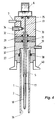
- the tube 2 concentrically surrounding the membrane 1 is in the region of the end 3 of the membrane 1 open on the front, while on the opposite Front 9, the membrane 1 is brought out gas-tight.
- the tube 2 is further provided with an opening 10 to which a throttle valve 11 and / or a pump 12 is connected.
- a heating element 13 surrounds the tube 2 in the Area of the end open at the end.
- the membrane 1 projects together with the tube 2 into the hot zone 14 Nitriding furnace 15.
- the tube 2 can not by means of a Flange shown to be attached to the wall of the nitriding furnace 15.
- a gas stream 16 is pumped out of the hot zone 50, the Flow rate through the throttle valve 11 is controllable.
- the Gas stream 16 flows around the membrane 1, causing hydrogen to pass through Permeation penetrates into an interior 17 of the membrane 1.
- the interior 17 the membrane 1 is via the valve 8 and the vacuum pump, not shown evacuable, 50 that a pressure builds up in the interior 17, the exclusively comes from the hydrogen and via the pressure sensor 6 is detected.
- the hydrogen pressure measured with the pressure sensor 6 is shown in a close equilibrium with the hydrogen partial pressure of the gas stream 16 and can therefore be used as a measure of the hydrogen content in the gas atmosphere of the nitriding furnace 15 can be used.
- a catalytic effect of the membrane 1 consisting of a palladium-silver alloy on the gas stream 16 is absent due to the flow rate of the gas stream 16. Measurements showed that a volume flow of 15 N cm 3 / min is sufficient even at temperatures up to 630 ° C. In order to also rule out a catalytic effect on the gas stream 16 on the part of the tube 2, this consists of a material which has no catalytic effect, for example quartz.
- the heating element 13 the gas stream 16 can be heated to a temperature required for permeation if the temperature of the hot zone 14 is too low.
- the content of hydrogen-containing compounds in the gas stream such as, for example, the ammonia (NH 3 ) frequently used for nitriding processes
- the splitting of hydrogen-containing compounds in the gas stream 16 can be achieved by changing the flow rate and / or the temperature of the gas stream 16 by changing them such that the surface 18 of the membrane 1 has a catalytic effect.
- both the delivery capacity of the pump 12 can be reduced and the temperature of the gas stream 16 can be increased via the heating element 13 to temperatures of, for example, over 1000 ° C.
- FIG. 1 shows an arrangement extending directly into the hot zone 14 of the nitriding furnace
- FIG. 2 shows an alternative embodiment in which the gas stream 16 from the nitriding furnace 16 is fed via a gas line 19 to an end connection 20 of the tube 2 .
- the arrangement which can be carried out as an autonomous measuring device, is operated without a pump 12, for which it is responsible that the nitriding process in the nitriding furnace 15 takes place at an overpressure, so that it is sufficient to use the gas stream 16 which sets itself automatically via the valve 11, which for example is precise Needle valve can be designed to control.
- the catalyst 21 is one Surround heating element 26, through which temperatures of over 1000 ° C to are generating.
- the alternative arrangement according to FIG. 3 makes it possible to the content of hydrogen and hydrogen-containing compounds in the Determine gas stream 16 in a very short time by the gas stream 16 is first passed through the bypass line 25, whereby the content of pure hydrogen can be determined in the undecomposed gas stream 16, and in Connection flows over the catalyst 21, so that a cleavage For example, ammonia and the pressure sensor 6 the pressure of a gas stream 16 enriched with hydrogen. The difference of the two hydrogen pressures in turn allows the content to be calculated of ammonia in the gas stream 16.
- the tube 2 concentrically surrounds the membrane 1 and partially the tubular one Hollow chamber 5, with the tube 2 at the front end 3 of the membrane 1 this protrudes a certain length in the axial direction.
- the steel one manufactured tube 2 is enamelled on its inner surface with a ceramic exclude a catalytic effect on the gas stream 16.
- the pipe 2 is held in a central bore 37 in the block elements 27 and 28 and is sealed to the outside by means of an annular seal 38.
- One in the between the outer lateral surface 18 of the membrane 1 and the inner surface 36 of the tube 2 formed in the annular gap flowing gas stream 16 passes an outflow connection 39 to the throttle valve 11 and / or the pump 12.
- the content of hydrogen and optionally also of hydrogen-containing compounds in a gas mixture can be determined in a simple and inexpensive manner. This is important for determining key figures, such as the nitriding key number K N , which are necessary for the process control of heat treatment processes. With the method described above, it is possible to determine the content of pure hydrogen even at high temperatures of more than 500 ° C., without the result being falsified by catalytic splitting of hydrogen-containing compounds.
- Such a method is suitable for the analysis of various process gases and can be achieved by using a suitable material for the membrane 1 also for the determination of substances other than hydrogen and from them derived key figures can be modified easily and quickly.
Landscapes
- Chemical & Material Sciences (AREA)
- Life Sciences & Earth Sciences (AREA)
- Engineering & Computer Science (AREA)
- Health & Medical Sciences (AREA)
- Analytical Chemistry (AREA)
- Food Science & Technology (AREA)
- Medicinal Chemistry (AREA)
- Physics & Mathematics (AREA)
- Combustion & Propulsion (AREA)
- Biochemistry (AREA)
- General Health & Medical Sciences (AREA)
- General Physics & Mathematics (AREA)
- Immunology (AREA)
- Pathology (AREA)
- Investigating Or Analyzing Non-Biological Materials By The Use Of Chemical Means (AREA)
- Separation Using Semi-Permeable Membranes (AREA)
- Hydrogen, Water And Hydrids (AREA)
Priority Applications (4)
| Application Number | Priority Date | Filing Date | Title |
|---|---|---|---|
| ES97117290T ES2154439T3 (es) | 1997-10-07 | 1997-10-07 | Procedimiento y dispositivo para la determinacion cuantitativa del contenido de hidrogeno libre y/o combinado. |
| DE59703064T DE59703064D1 (de) | 1997-10-07 | 1997-10-07 | Verfahren und Vorrichtung zur quantitativen Bestimmung des Gehalts von reinem und/oder gebundenem Wasserstoff |
| AT97117290T ATE199460T1 (de) | 1997-10-07 | 1997-10-07 | Verfahren und vorrichtung zur quantitativen bestimmung des gehalts von reinem und/oder gebundenem wasserstoff |
| EP97117290A EP0909951B1 (fr) | 1997-10-07 | 1997-10-07 | Méthode et dispositif pour la détermination quantitiv de hydrogène lié et/ou libre |
Applications Claiming Priority (1)
| Application Number | Priority Date | Filing Date | Title |
|---|---|---|---|
| EP97117290A EP0909951B1 (fr) | 1997-10-07 | 1997-10-07 | Méthode et dispositif pour la détermination quantitiv de hydrogène lié et/ou libre |
Publications (2)
| Publication Number | Publication Date |
|---|---|
| EP0909951A1 true EP0909951A1 (fr) | 1999-04-21 |
| EP0909951B1 EP0909951B1 (fr) | 2001-02-28 |
Family
ID=8227448
Family Applications (1)
| Application Number | Title | Priority Date | Filing Date |
|---|---|---|---|
| EP97117290A Expired - Lifetime EP0909951B1 (fr) | 1997-10-07 | 1997-10-07 | Méthode et dispositif pour la détermination quantitiv de hydrogène lié et/ou libre |
Country Status (4)
| Country | Link |
|---|---|
| EP (1) | EP0909951B1 (fr) |
| AT (1) | ATE199460T1 (fr) |
| DE (1) | DE59703064D1 (fr) |
| ES (1) | ES2154439T3 (fr) |
Cited By (2)
| Publication number | Priority date | Publication date | Assignee | Title |
|---|---|---|---|---|
| DE10209760B4 (de) * | 2001-03-08 | 2013-03-28 | General Electric Canada Inc. | Mikro-Brennstoffzellen-Sensoreinrichtung und Verfahren zum Anpasen der Sensoransprechzeit |
| US9399811B2 (en) | 2010-02-15 | 2016-07-26 | Robert Bosch Gmbh | Method for carbonitriding at least one component in a treatment chamber |
Citations (3)
| Publication number | Priority date | Publication date | Assignee | Title |
|---|---|---|---|---|
| US4882032A (en) * | 1988-06-27 | 1989-11-21 | General Motors Corporation | Hydrogen probe |
| US5088315A (en) * | 1990-09-12 | 1992-02-18 | Johnson Walter A | Gas purity analyzer and method |
| US5668301A (en) * | 1994-12-30 | 1997-09-16 | The United States Of America As Represented By The Administrator Of The National Aeronautics And Space Administration | Method and apparatus for the detection of hydrogen using a metal alloy |
-
1997
- 1997-10-07 EP EP97117290A patent/EP0909951B1/fr not_active Expired - Lifetime
- 1997-10-07 DE DE59703064T patent/DE59703064D1/de not_active Expired - Lifetime
- 1997-10-07 ES ES97117290T patent/ES2154439T3/es not_active Expired - Lifetime
- 1997-10-07 AT AT97117290T patent/ATE199460T1/de active
Patent Citations (3)
| Publication number | Priority date | Publication date | Assignee | Title |
|---|---|---|---|---|
| US4882032A (en) * | 1988-06-27 | 1989-11-21 | General Motors Corporation | Hydrogen probe |
| US5088315A (en) * | 1990-09-12 | 1992-02-18 | Johnson Walter A | Gas purity analyzer and method |
| US5668301A (en) * | 1994-12-30 | 1997-09-16 | The United States Of America As Represented By The Administrator Of The National Aeronautics And Space Administration | Method and apparatus for the detection of hydrogen using a metal alloy |
Cited By (2)
| Publication number | Priority date | Publication date | Assignee | Title |
|---|---|---|---|---|
| DE10209760B4 (de) * | 2001-03-08 | 2013-03-28 | General Electric Canada Inc. | Mikro-Brennstoffzellen-Sensoreinrichtung und Verfahren zum Anpasen der Sensoransprechzeit |
| US9399811B2 (en) | 2010-02-15 | 2016-07-26 | Robert Bosch Gmbh | Method for carbonitriding at least one component in a treatment chamber |
Also Published As
| Publication number | Publication date |
|---|---|
| ES2154439T3 (es) | 2001-04-01 |
| ATE199460T1 (de) | 2001-03-15 |
| EP0909951B1 (fr) | 2001-02-28 |
| DE59703064D1 (de) | 2001-04-05 |
Similar Documents
| Publication | Publication Date | Title |
|---|---|---|
| DE2810492C2 (fr) | ||
| DE60223429T2 (de) | Verfahren und Vorrichtung zum Aufkohlen | |
| EP0803731B1 (fr) | Méthode et appareil pour la détermination en continu de produits d'oxydation en forme de gaz | |
| DE2218776A1 (de) | Vorrichtung und Verfahren zur Analyse des Gehalts von Luft an Pollutionssubstanzen | |
| DE2264718C3 (de) | Verfahren zur Bestimmung von Stickstoffdioxid in Gasgemischen | |
| DE69125343T2 (de) | Einspritzströmungsanalyse von gesamt-anorganischem Phosphat | |
| DE2520444A1 (de) | Verfahren und vorrichtung zum kontinuierlichen messen der wasserstoffkonzentration in argongas | |
| CH628092A5 (de) | Verfahren und vorrichtung zur regelung des kohlenstoffpegels eines chemisch reagierenden gasgemisches. | |
| DE1498653A1 (de) | Verfahren und Vorrichtung zur Oberflaechenmessung von Feststoffen | |
| DE4437895C1 (de) | Vorrichtung zur Erzeugung von Sauerstoff | |
| DE2839315C2 (de) | Verfahren zur Steuerung der Stahlherstellung | |
| EP0909951B1 (fr) | Méthode et dispositif pour la détermination quantitiv de hydrogène lié et/ou libre | |
| DE2553756C2 (de) | Verwendung der kontinuierlichen Gichtgasanalyse zur Überwachung und Regelung des Hochofenganges und Vorrichtung hierfür | |
| DE19733837A1 (de) | On-Line-Analyse der Prozeßgase bei der Herstellung von Keten | |
| AT408994B (de) | Vorrichtung zur wärmebehandlung von werkstücken, insbesondere zum gasnitrieren, nitrocarburieren und oxidieren | |
| DE2904872A1 (de) | Verfahren zur erzeugung eines no/no tief 2 -pruefgasgemisches sowie vorrichtung zu seiner durchfuehrung | |
| DE1598366C3 (de) | Verfahren und Vorrichtung zur Bestimmung des Sauerstoffbedarfs oxidierbarer Stoffe | |
| AT391311B (de) | Verfahren zur herstellung von pruefgasgemischen mit stickstoffoxiden und vorrichtung zur durchfuehrungeines solchen verfahrens | |
| DE2348090C2 (de) | Verfahren zur kontinuierlichen Überführung von in einer Flüssigkeit gelösten Gaskomponenten in ein Trägergas | |
| WO2009112199A1 (fr) | Dispositif de mesure et montage de mesure pour déterminer la teneur de l'eau fraîche ou d'une eau résiduaire en un élément chimique ou en un autre paramètre de qualité de l'eau | |
| DE2045922B2 (de) | Vorrichtung zum Analysieren von Kohlenwasserstoffen und kohlenwasserstofihaltigen Gemischen | |
| EP1067383B1 (fr) | Méthode d'opération d'un appareil mélangeur de gaz, en particulier pour déterminer l'indice de Wobbe d'un gaz à tester | |
| DE102024126955A1 (de) | Analysegerät und Verfahren zur Analyse einer Probe | |
| DE29615312U1 (de) | Vorrichtung zur Wärmebehandlung von Materialien, insbesondere zum Gasnitrieren und Nitrocarburieren | |
| DE1175464B (de) | Verfahren zur Differentialthermoanalyse von Bodenproben |
Legal Events
| Date | Code | Title | Description |
|---|---|---|---|
| PUAI | Public reference made under article 153(3) epc to a published international application that has entered the european phase |
Free format text: ORIGINAL CODE: 0009012 |
|
| 17P | Request for examination filed |
Effective date: 19980417 |
|
| AK | Designated contracting states |
Kind code of ref document: A1 Designated state(s): AT BE CH DE ES FR GB IT LI NL SE |
|
| AKX | Designation fees paid |
Free format text: AT BE CH DE ES FR GB IT LI NL SE |
|
| GRAG | Despatch of communication of intention to grant |
Free format text: ORIGINAL CODE: EPIDOS AGRA |
|
| GRAG | Despatch of communication of intention to grant |
Free format text: ORIGINAL CODE: EPIDOS AGRA |
|
| GRAH | Despatch of communication of intention to grant a patent |
Free format text: ORIGINAL CODE: EPIDOS IGRA |
|
| 17Q | First examination report despatched |
Effective date: 20000721 |
|
| RAP1 | Party data changed (applicant data changed or rights of an application transferred) |
Owner name: IPSEN INTERNATIONAL GMBH |
|
| GRAH | Despatch of communication of intention to grant a patent |
Free format text: ORIGINAL CODE: EPIDOS IGRA |
|
| GRAA | (expected) grant |
Free format text: ORIGINAL CODE: 0009210 |
|
| AK | Designated contracting states |
Kind code of ref document: B1 Designated state(s): AT BE CH DE ES FR GB IT LI NL SE |
|
| REF | Corresponds to: |
Ref document number: 199460 Country of ref document: AT Date of ref document: 20010315 Kind code of ref document: T |
|
| REG | Reference to a national code |
Ref country code: CH Ref legal event code: NV Representative=s name: E. BLUM & CO. PATENTANWAELTE Ref country code: CH Ref legal event code: EP |
|
| REG | Reference to a national code |
Ref country code: ES Ref legal event code: FG2A Ref document number: 2154439 Country of ref document: ES Kind code of ref document: T3 |
|
| GBT | Gb: translation of ep patent filed (gb section 77(6)(a)/1977) |
Effective date: 20010313 |
|
| REF | Corresponds to: |
Ref document number: 59703064 Country of ref document: DE Date of ref document: 20010405 |
|
| ET | Fr: translation filed | ||
| ITF | It: translation for a ep patent filed | ||
| REG | Reference to a national code |
Ref country code: GB Ref legal event code: IF02 |
|
| PLBE | No opposition filed within time limit |
Free format text: ORIGINAL CODE: 0009261 |
|
| STAA | Information on the status of an ep patent application or granted ep patent |
Free format text: STATUS: NO OPPOSITION FILED WITHIN TIME LIMIT |
|
| 26N | No opposition filed | ||
| PGFP | Annual fee paid to national office [announced via postgrant information from national office to epo] |
Ref country code: BE Payment date: 20051108 Year of fee payment: 9 |
|
| REG | Reference to a national code |
Ref country code: CH Ref legal event code: PFA Owner name: IPSEN INTERNATIONAL GMBH Free format text: IPSEN INTERNATIONAL GMBH#FLUTSTRASSE 52#47533 KLEVE (DE) -TRANSFER TO- IPSEN INTERNATIONAL GMBH#FLUTSTRASSE 52#47533 KLEVE (DE) |
|
| BERE | Be: lapsed |
Owner name: *IPSEN INTERNATIONAL G.M.B.H. Effective date: 20061031 |
|
| PG25 | Lapsed in a contracting state [announced via postgrant information from national office to epo] |
Ref country code: BE Free format text: LAPSE BECAUSE OF FAILURE TO SUBMIT A TRANSLATION OF THE DESCRIPTION OR TO PAY THE FEE WITHIN THE PRESCRIBED TIME-LIMIT Effective date: 20061031 |
|
| PGFP | Annual fee paid to national office [announced via postgrant information from national office to epo] |
Ref country code: SE Payment date: 20131022 Year of fee payment: 17 Ref country code: GB Payment date: 20131021 Year of fee payment: 17 Ref country code: AT Payment date: 20131011 Year of fee payment: 17 Ref country code: FR Payment date: 20131022 Year of fee payment: 17 Ref country code: DE Payment date: 20131021 Year of fee payment: 17 Ref country code: CH Payment date: 20131021 Year of fee payment: 17 |
|
| PGFP | Annual fee paid to national office [announced via postgrant information from national office to epo] |
Ref country code: NL Payment date: 20131022 Year of fee payment: 17 Ref country code: ES Payment date: 20131029 Year of fee payment: 17 Ref country code: IT Payment date: 20131029 Year of fee payment: 17 |
|
| REG | Reference to a national code |
Ref country code: DE Ref legal event code: R119 Ref document number: 59703064 Country of ref document: DE |
|
| REG | Reference to a national code |
Ref country code: NL Ref legal event code: V1 Effective date: 20150501 |
|
| REG | Reference to a national code |
Ref country code: CH Ref legal event code: PL |
|
| REG | Reference to a national code |
Ref country code: SE Ref legal event code: EUG |
|
| REG | Reference to a national code |
Ref country code: AT Ref legal event code: MM01 Ref document number: 199460 Country of ref document: AT Kind code of ref document: T Effective date: 20141007 |
|
| GBPC | Gb: european patent ceased through non-payment of renewal fee |
Effective date: 20141007 |
|
| PG25 | Lapsed in a contracting state [announced via postgrant information from national office to epo] |
Ref country code: GB Free format text: LAPSE BECAUSE OF NON-PAYMENT OF DUE FEES Effective date: 20141007 Ref country code: CH Free format text: LAPSE BECAUSE OF NON-PAYMENT OF DUE FEES Effective date: 20141031 Ref country code: DE Free format text: LAPSE BECAUSE OF NON-PAYMENT OF DUE FEES Effective date: 20150501 Ref country code: SE Free format text: LAPSE BECAUSE OF NON-PAYMENT OF DUE FEES Effective date: 20141008 Ref country code: LI Free format text: LAPSE BECAUSE OF NON-PAYMENT OF DUE FEES Effective date: 20141031 |
|
| REG | Reference to a national code |
Ref country code: FR Ref legal event code: ST Effective date: 20150630 |
|
| PG25 | Lapsed in a contracting state [announced via postgrant information from national office to epo] |
Ref country code: NL Free format text: LAPSE BECAUSE OF NON-PAYMENT OF DUE FEES Effective date: 20150501 Ref country code: IT Free format text: LAPSE BECAUSE OF NON-PAYMENT OF DUE FEES Effective date: 20141007 Ref country code: AT Free format text: LAPSE BECAUSE OF NON-PAYMENT OF DUE FEES Effective date: 20141007 Ref country code: FR Free format text: LAPSE BECAUSE OF NON-PAYMENT OF DUE FEES Effective date: 20141031 |
|
| REG | Reference to a national code |
Ref country code: ES Ref legal event code: FD2A Effective date: 20151126 |
|
| PG25 | Lapsed in a contracting state [announced via postgrant information from national office to epo] |
Ref country code: ES Free format text: LAPSE BECAUSE OF NON-PAYMENT OF DUE FEES Effective date: 20141008 |