EP0910001A2 - Satellite attitude determination - Google Patents
Satellite attitude determination Download PDFInfo
- Publication number
- EP0910001A2 EP0910001A2 EP98114909A EP98114909A EP0910001A2 EP 0910001 A2 EP0910001 A2 EP 0910001A2 EP 98114909 A EP98114909 A EP 98114909A EP 98114909 A EP98114909 A EP 98114909A EP 0910001 A2 EP0910001 A2 EP 0910001A2
- Authority
- EP
- European Patent Office
- Prior art keywords
- satellite
- signal
- satellites
- attitude
- producing
- Prior art date
- Legal status (The legal status is an assumption and is not a legal conclusion. Google has not performed a legal analysis and makes no representation as to the accuracy of the status listed.)
- Granted
Links
Images

Classifications
-
- B—PERFORMING OPERATIONS; TRANSPORTING
- B64—AIRCRAFT; AVIATION; COSMONAUTICS
- B64G—COSMONAUTICS; VEHICLES OR EQUIPMENT THEREFOR
- B64G1/00—Cosmonautic vehicles
- B64G1/22—Parts of, or equipment specially adapted for fitting in or to, cosmonautic vehicles
- B64G1/24—Guiding or controlling apparatus, e.g. for attitude control
- B64G1/28—Guiding or controlling apparatus, e.g. for attitude control using inertia or gyro effect
- B64G1/285—Guiding or controlling apparatus, e.g. for attitude control using inertia or gyro effect using momentum wheels
-
- B—PERFORMING OPERATIONS; TRANSPORTING
- B64—AIRCRAFT; AVIATION; COSMONAUTICS
- B64G—COSMONAUTICS; VEHICLES OR EQUIPMENT THEREFOR
- B64G1/00—Cosmonautic vehicles
- B64G1/22—Parts of, or equipment specially adapted for fitting in or to, cosmonautic vehicles
- B64G1/24—Guiding or controlling apparatus, e.g. for attitude control
- B64G1/244—Spacecraft control systems
-
- B—PERFORMING OPERATIONS; TRANSPORTING
- B64—AIRCRAFT; AVIATION; COSMONAUTICS
- B64G—COSMONAUTICS; VEHICLES OR EQUIPMENT THEREFOR
- B64G1/00—Cosmonautic vehicles
- B64G1/22—Parts of, or equipment specially adapted for fitting in or to, cosmonautic vehicles
- B64G1/24—Guiding or controlling apparatus, e.g. for attitude control
- B64G1/36—Guiding or controlling apparatus, e.g. for attitude control using sensors, e.g. sun-sensors, horizon sensors
-
- B—PERFORMING OPERATIONS; TRANSPORTING
- B64—AIRCRAFT; AVIATION; COSMONAUTICS
- B64G—COSMONAUTICS; VEHICLES OR EQUIPMENT THEREFOR
- B64G1/00—Cosmonautic vehicles
- B64G1/22—Parts of, or equipment specially adapted for fitting in or to, cosmonautic vehicles
- B64G1/24—Guiding or controlling apparatus, e.g. for attitude control
- B64G1/36—Guiding or controlling apparatus, e.g. for attitude control using sensors, e.g. sun-sensors, horizon sensors
- B64G1/361—Guiding or controlling apparatus, e.g. for attitude control using sensors, e.g. sun-sensors, horizon sensors using star sensors
-
- G—PHYSICS
- G01—MEASURING; TESTING
- G01S—RADIO DIRECTION-FINDING; RADIO NAVIGATION; DETERMINING DISTANCE OR VELOCITY BY USE OF RADIO WAVES; LOCATING OR PRESENCE-DETECTING BY USE OF THE REFLECTION OR RERADIATION OF RADIO WAVES; ANALOGOUS ARRANGEMENTS USING OTHER WAVES
- G01S19/00—Satellite radio beacon positioning systems; Determining position, velocity or attitude using signals transmitted by such systems
- G01S19/38—Determining a navigation solution using signals transmitted by a satellite radio beacon positioning system
- G01S19/39—Determining a navigation solution using signals transmitted by a satellite radio beacon positioning system the satellite radio beacon positioning system transmitting time-stamped messages, e.g. GPS [Global Positioning System], GLONASS [Global Orbiting Navigation Satellite System] or GALILEO
- G01S19/53—Determining attitude
Definitions
- This invention relates to satellite attitude control, in particular, satellite attitude determination using GPS and intersatellite line of sight communications.
- attitude (roll, pitch and yaw) of an orbiting satellite is controlled to maintain a correct orientation of devices, such as solar panels to the sun and antenna to the earth or space craft.
- devices such as solar panels to the sun and antenna to the earth or space craft.
- the common way to sense attitude is with object sensors, most commonly star sensors. Star trackers are expensive complicated devices.
- An object of the present invention is to determine the attitude of a satellite without on board dedicated attitude determining devices, such as star trackers.
- the position of two or more satellites in an orbit is transmitted to one satellite.
- the one satellite determines the azimuth and elevation to the satellites transmitting their position.
- the one satellite determines the difference in position in the orbit between it and each of the other satellites using its own position and the transmitted position. It then uses that difference and the azimuth and elevation to each of the other satellites to determine its yaw, pitch and roll.
- satellites determine their position using an on-board GPS receiver and transmit the position to the one satellite by a line of sight (LOS) intersatellite communications link, such as a laser communications system.
- the one satellite has receiver for each satellite that is oriented in two axis to establish the link and the orientation of the receiver provides the azimuth and elevation to the satellite providing its own position information.
- LOS line of sight
- a feature of the present invention is that it can be deployed in satellite systems that already use an on board GPS and that transmit and receive data, telephony, over a line sight communications link to provide uniform satellite to earth links. Another feature is that the invention eliminates the need for star trackers and considerably lowers the cost of each satellite by using information and equipment already on the satellite for other purpose, i.e., the GPS and communications link hardware.
- Fig. 1 shows a plurality of satellites S n , assumed to be in an orbit.
- Each satellite contains its own on board GPS receiver and an intersatellite communication link ISL, such as a laser transceiver system, for relaying data and other information between the satellites that is transmitted from one location to another location on the earth.
- ISL comprises a plurality of gimbaled communication link input/output devices 10, such as a mirror or telescope with a laser based system.
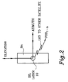
- the devices 10 are located on the surface of the satellite, as depicted in Fig. 2.
- the input/output devices 10 can be pointed at a satellite, i.e., oriented in two dimensions (elevation and azimuth) relative to the satellite to establish communications with another satellite.
- each satellite S n has a plurality of these lens or directional antennas 10 around its surface, as shown only for satellite S 0 enabling communication with satellites three dimensionally simply by pointing the input/output or lens to make the communications connection without rotating the satellite, enabling the satellites attitude relative to the earth to be controlled independently for communications and orientation of solar panels.
- Each satellite comprises what is shown for satellite 0, which for this discussion is sometimes called the "home” satellite, the other satellites being the “reference” satellites.
- each satellite is a home satellite in determining its own attitude using the GPS position of the other or reference satellites and the line of sight bearing to the reference satellite, which is provided by the orientation of the lens 10.
- Each satellite transmits its GPS position, line of sight (LOS), by sighting another satellite with a lens 10.
- satellite S0 uses satellite S0 as example, it receives, signals Pos 1-n , by an associated lens 10 for each satellite and likewise sends its GPS position back to the other satellites using the same lens.
- Each lens 10 produces an elevation and azimuth signal Az n , El n , that represents the LOS to the other satellite.
- Those signals are applied to a signal processor 12, which is programmed, as explained below, to perform a coordinate transformation that yield the bearing B 1-n to each satellite.
- the GPS on satellite S 0 produces the local or home GPS position signal, Pos 0, which, in addition to being applied to the lens 10 for transmission to the other satellites, is subtracted from received positions for the other satellites.
- the difference between the GPS position of the home satellite and the position of the remote or what may be called "reference" satellite is position vector, signal r n , in earth or GPS reference coordinates to the reference satellite.
- the difference signal is applied to the signal processor 12 to produce attitude signals (yaw, pitch and roll) that are supplied to an attitude control system 14 that uses those signals to control the satellite's attitude devices, such as momentum wheels, to regulate the satellite's attitude.
- the signal processor 12 is programmed to carry out the following attitude determination process using the signals generated as described above.
- the angles El n and Az n specify the direction to the target or reference satellite.
- This Cartesian coordinate conversion relates the gimbal azimuth (Az) and elevation (El) angle deflections to the line of sight (LOS) unit vector ( ) :
- ( b ) cos(E1)cos(Az) cos(E1)sin(Az) sin(E1)
- the direction to target satellites is also specified in an earth referenced frame by the position vector r i , which represents the difference between the GPS measured position of satellite 1 and satellite 0.
- the direction cosine matrix A that defines the spacecraft attitude is obtained by first forming two matrices - R and B.
- the number of unit vectors n is determined by the number of laser communication ("com”) systems resident on a satellite. A minimum of 2 are required for attitude determination.
- the matrices R and B are decomposed using the singular value decomposition (SVD).
- the singular value decomposition is a mathematical tool often used for analyzing a mapping from one vector space (such as an earth referenced vector) into another vector space (such as a body reference vector).
- U 1 and U 2 are 3x3, ⁇ 1 and ⁇ 2 are 3xn, and V ' / 1 and V ' / 2 are nxn.
- the matrices U 1 , U 2 , V ' / 1, and V ' / 2 are unitary (i.e. the columns are orthogonal and have unit magnitude).
- the matrices ⁇ 1 and ⁇ 2 are diagonal with real non-negative elements. The elements of ⁇ 1 and ⁇ 2 are known as singular values.
- the direction cosine matrix A can be obtained by multiplying the unitary matrix U 2 with the transpose of the unitary matrix U 1 .
- A U 2 U' 1
- the attitude or direction cosine matrix A has three row and three columns as shown in equation 6.
- A A 11 A 21 A 31 A 12 A 22 A 32 A 13 A 23 A 33
- the elements of the attitude matrix can be used to derive the satellite roll, pitch, and yaw angles.
- the satellite pitch attitude ⁇ is calculated using equation 7.
- ⁇ tan -1 - A 13 A 2 11 + A 2 12
- the satellite roll and yaw computations are defined by equations 8 and 9 respectively.
- attitude can be described using quaternions. Quaternions are employed to avoid computational singularites when the pitch attitude ⁇ approaches 90 degrees.
Landscapes
- Engineering & Computer Science (AREA)
- Remote Sensing (AREA)
- Radar, Positioning & Navigation (AREA)
- Chemical & Material Sciences (AREA)
- Combustion & Propulsion (AREA)
- Aviation & Aerospace Engineering (AREA)
- Automation & Control Theory (AREA)
- Computer Networks & Wireless Communication (AREA)
- Physics & Mathematics (AREA)
- General Physics & Mathematics (AREA)
- Position Fixing By Use Of Radio Waves (AREA)
- Radio Relay Systems (AREA)
Abstract
Description


Claims (5)
- A method for satellite attitude determination, characterized by:producing a first signal manifesting a position of a first satellite on a first frame of reference and transmitting the first signal from the first satellite to second satellite over a line of sight communications link path;producing a second signal manifesting a position of a third satellite on the first frame of reference and transmitting the second signal from the third satellite to the second satellite over a line of sight communications link path;producing a line of sight signal on the second satellite that indicates an azimuth and elevation from the second satellite to the first satellite and the third satellite;producing position difference signals manifesting the difference in position on the first frame of reference between the second satellite and the first and second satellites using the first and third position signals;producing a second position signal manifesting the position of the second satellite on the first frame of reference; andcontrolling the attitude of the second satellite using signals manifesting yaw, pitch and roll derived from by correlating the position difference signals and the line of sight signals to a common frame of reference.
- The method of claim 1, further characterized by:producing the first, second and third signals from GPS receivers on first, second and third satellites.
- The method of claim 2, further characterized by:producing the line of sight signal by resolving the elevation and azimuth, on the second satellite, of a laser directed at each of the first and second satellites for providing an intersatellite communications link between the first, second and third satellites.
- A satellite characterized by:first means for receiving from each of a plurality of remote satellites a remote position signal that indicates the position of the remote satellite on a first frame of reference and for producing a position vector signal for each of the plurality of satellites as a function of the remote position signal and the position of the satellite, the vector signal representing the bearing to the remote satellite on the first frame of reference;second means for providing a line of sight communications link to each remote satellite and for providing a sight signal representing the azimuth and elevation from the satellite to the each remote satellite;signal processing means for providing attitude signals representing the yaw, pitch and roll of the satellite around the satellite axis by correlating the position vector signal and the sight signal to the satellite axis; anda satellite attitude system responsive to the attitude signals for controlling the yaw pitch and roll of the satellite.
- A method for satellite attitude determination characterized by:producing a GPS position with a GPS receiver on each of said plurality of satellites in a location around the earth;transmitting the position signal to one of the plurality of satellites by a line of sight communications link;determining the elevation and azimuth from the one satellite and each of the plurality of satellites from the orientation of a receiving device for the position signal;determining the attitude of the one satellite using the elevation and azimuth to each of the plurality of satellites and the position signals received at the one satellite by the communications link.
Applications Claiming Priority (2)
| Application Number | Priority Date | Filing Date | Title |
|---|---|---|---|
| US08/909,781 US5959576A (en) | 1997-08-12 | 1997-08-12 | Satellite attitude determination using GPS and intersatellite line of sight communications |
| US909781 | 1997-08-12 |
Publications (3)
| Publication Number | Publication Date |
|---|---|
| EP0910001A2 true EP0910001A2 (en) | 1999-04-21 |
| EP0910001A3 EP0910001A3 (en) | 2000-08-23 |
| EP0910001B1 EP0910001B1 (en) | 2005-04-27 |
Family
ID=25427822
Family Applications (1)
| Application Number | Title | Priority Date | Filing Date |
|---|---|---|---|
| EP98114909A Expired - Lifetime EP0910001B1 (en) | 1997-08-12 | 1998-08-08 | Satellite attitude determination |
Country Status (2)
| Country | Link |
|---|---|
| US (1) | US5959576A (en) |
| EP (1) | EP0910001B1 (en) |
Cited By (5)
| Publication number | Priority date | Publication date | Assignee | Title |
|---|---|---|---|---|
| KR20010039649A (en) * | 1999-06-29 | 2001-05-15 | 윌리엄 이. 갈라스 | Ephemeris/attitude reference determination using on-board optics and other satellite ephemeris |
| US6484073B1 (en) | 1998-10-15 | 2002-11-19 | Astrium Gmbh | Method and device for determining the position of communication satellites |
| CN103852082A (en) * | 2012-11-30 | 2014-06-11 | 上海航天控制工程研究所 | Inter-satellite measurement and gyro attitude orbit integrated smoothing estimation method |
| CN104142686A (en) * | 2014-07-16 | 2014-11-12 | 北京控制工程研究所 | A control method for autonomous formation flight of satellites |
| WO2017053096A1 (en) * | 2015-09-23 | 2017-03-30 | Qualcomm Incorporated | Acquiring leo satellites without compass |
Families Citing this family (12)
| Publication number | Priority date | Publication date | Assignee | Title |
|---|---|---|---|---|
| US6195044B1 (en) * | 1998-06-19 | 2001-02-27 | Hughes Electronics Corporation | Laser crosslink satellite attitude determination system and method |
| US6219593B1 (en) * | 1999-03-01 | 2001-04-17 | Motorola, Inc. | Method and apparatus for attitude determination in a multi-nodal system |
| US6463366B2 (en) | 2000-03-10 | 2002-10-08 | Schafer Corp | Attitude determination and alignment using electro-optical sensors and global navigation satellites |
| US6621453B2 (en) * | 2001-09-21 | 2003-09-16 | Honeywell International Inc. | Satellite attitude adjustment for GPS initialization |
| US7366125B1 (en) | 2003-07-24 | 2008-04-29 | Bbn Technologies Corp. | Extensible satellite communication system |
| US7079944B2 (en) | 2003-08-18 | 2006-07-18 | Textron Systems Corporation | System and method for determining orientation based on solar positioning |
| US7889125B2 (en) * | 2005-03-15 | 2011-02-15 | Honeywell International Inc. | Adjusting processor clock information using a clock drift estimate |
| US7877173B2 (en) * | 2007-07-05 | 2011-01-25 | The Boeing Company | Method and apparatus for determining a satellite attitude using crosslink reference signals |
| FR2988860A1 (en) * | 2012-03-29 | 2013-10-04 | Astrium Sas | SPACIAL ERROR CALIBRATION METHOD, METHOD AND SYSTEM FOR ATTITUDE ESTIMATION OF A GEAR |
| CN104064869B (en) * | 2014-06-13 | 2016-10-05 | 北京航天万达高科技有限公司 | Biquaternion antenna for satellite communication in motion control method and system based on MEMS inertial navigation |
| CN111854764B (en) * | 2020-07-20 | 2022-05-27 | 中国科学院微小卫星创新研究院 | Spacecraft attitude determination method and system based on inter-satellite measurement information |
| CN116039972B (en) * | 2022-12-01 | 2025-12-19 | 北京微纳星空科技股份有限公司 | Satellite control system, method, electronic equipment and storage medium |
Family Cites Families (7)
| Publication number | Priority date | Publication date | Assignee | Title |
|---|---|---|---|---|
| JPS60104499A (en) * | 1983-11-11 | 1985-06-08 | 株式会社日立製作所 | Attitude determination system |
| US4883244A (en) * | 1987-12-23 | 1989-11-28 | Hughes Aircraft Company | Satellite attitude determination and control system with agile beam sensing |
| US5101356A (en) * | 1989-11-21 | 1992-03-31 | Unisys Corporation | Moving vehicle attitude measuring system |
| US5546309A (en) * | 1993-10-20 | 1996-08-13 | The Charles Stark Draper Laboratory, Inc. | Apparatus and method for autonomous satellite attitude sensing |
| US5543804A (en) * | 1994-09-13 | 1996-08-06 | Litton Systems, Inc. | Navagation apparatus with improved attitude determination |
| US5561432A (en) * | 1995-05-12 | 1996-10-01 | Trimble Navigation | Out of plane antenna vector system and method |
| FR2741955B1 (en) * | 1995-12-01 | 1998-02-06 | Matra Marconi Space France | SATELLITE ATTITUDE MEASURING METHOD AND DEVICE |
-
1997
- 1997-08-12 US US08/909,781 patent/US5959576A/en not_active Expired - Lifetime
-
1998
- 1998-08-08 EP EP98114909A patent/EP0910001B1/en not_active Expired - Lifetime
Cited By (8)
| Publication number | Priority date | Publication date | Assignee | Title |
|---|---|---|---|---|
| US6484073B1 (en) | 1998-10-15 | 2002-11-19 | Astrium Gmbh | Method and device for determining the position of communication satellites |
| KR20010039649A (en) * | 1999-06-29 | 2001-05-15 | 윌리엄 이. 갈라스 | Ephemeris/attitude reference determination using on-board optics and other satellite ephemeris |
| CN103852082A (en) * | 2012-11-30 | 2014-06-11 | 上海航天控制工程研究所 | Inter-satellite measurement and gyro attitude orbit integrated smoothing estimation method |
| CN103852082B (en) * | 2012-11-30 | 2017-04-19 | 上海航天控制工程研究所 | Inter-satellite measurement and gyro attitude orbit integrated smoothing estimation method |
| CN104142686A (en) * | 2014-07-16 | 2014-11-12 | 北京控制工程研究所 | A control method for autonomous formation flight of satellites |
| CN104142686B (en) * | 2014-07-16 | 2016-06-29 | 北京控制工程研究所 | A kind of satellite Autonomous formation flight control method |
| WO2017053096A1 (en) * | 2015-09-23 | 2017-03-30 | Qualcomm Incorporated | Acquiring leo satellites without compass |
| US9673888B2 (en) | 2015-09-23 | 2017-06-06 | Qualcomm Incorporated | Acquiring LEO satellites without compass |
Also Published As
| Publication number | Publication date |
|---|---|
| EP0910001A3 (en) | 2000-08-23 |
| EP0910001B1 (en) | 2005-04-27 |
| US5959576A (en) | 1999-09-28 |
Similar Documents
| Publication | Publication Date | Title |
|---|---|---|
| EP0910001B1 (en) | Satellite attitude determination | |
| US7877173B2 (en) | Method and apparatus for determining a satellite attitude using crosslink reference signals | |
| US6377211B1 (en) | Apparatus and method for pointing a directional device from a moving vehicle toward a spacecraft | |
| US5412574A (en) | Method of attitude determination using earth and star sensors | |
| US8213803B2 (en) | Method and system for laser based communication | |
| US5809457A (en) | Inertial pointing and positioning system | |
| US6266616B1 (en) | Confused-in-space stellar attitude acquisition using multiple star trackers | |
| US7095376B1 (en) | System and method for pointing and control of an antenna | |
| US5119225A (en) | Multiple access communication system | |
| CA1314609C (en) | Distributed-array radar system comprising an array of interconnected elementary satellites | |
| CN101226058B (en) | A Realization Method of Real-time Transmission of Satellite Side Swing Maneuvering Image | |
| US6504502B1 (en) | Method and apparatus for spacecraft antenna beam pointing correction | |
| US6441776B1 (en) | Method and apparatus for spacecraft payload pointing registration | |
| US6725012B1 (en) | Method for deploying an orbiting sparse array antenna | |
| US6087646A (en) | Wide field-of-view radiation sensors and methods | |
| US6142423A (en) | Ephemeris/attitude reference determination using on-board optics and other satellite ephemeris | |
| US6771217B1 (en) | Phased array pointing determination using inverse pseudo-beacon | |
| US6288670B1 (en) | Combined roll-yaw spacecraft steering method for low earth orbit target trajectory compensation | |
| US20050071055A1 (en) | Refinement of spacecraft angular velocity and attitude estimates using star data | |
| CN109239754A (en) | A method of microsatellite relative attitude is determined using double array antennas | |
| US20080118247A1 (en) | Method and apparatus for hemispherical retargeting | |
| JP3384865B2 (en) | Multiple satellite control method and multiple satellite control device | |
| US6133870A (en) | Ephemeris determination using intersatellite ranging and ephemeris knowledge of other satellites | |
| US7256734B2 (en) | Spot beam antenna boresight calibration using GPS receivers | |
| US6216983B1 (en) | Ephemeris/attitude reference determination using communications links |
Legal Events
| Date | Code | Title | Description |
|---|---|---|---|
| PUAI | Public reference made under article 153(3) epc to a published international application that has entered the european phase |
Free format text: ORIGINAL CODE: 0009012 |
|
| AK | Designated contracting states |
Kind code of ref document: A2 Designated state(s): FR |
|
| AX | Request for extension of the european patent |
Free format text: AL;LT;LV;MK;RO;SI |
|
| PUAL | Search report despatched |
Free format text: ORIGINAL CODE: 0009013 |
|
| AK | Designated contracting states |
Kind code of ref document: A3 Designated state(s): AT BE CH CY DE DK ES FI FR GB GR IE IT LI LU MC NL PT SE |
|
| AX | Request for extension of the european patent |
Free format text: AL;LT;LV;MK;RO;SI |
|
| RIC1 | Information provided on ipc code assigned before grant |
Free format text: 7G 05D 1/08 A, 7G 01C 21/24 B, 7G 01S 5/02 B |
|
| 17P | Request for examination filed |
Effective date: 20000720 |
|
| AKX | Designation fees paid |
Free format text: FR |
|
| REG | Reference to a national code |
Ref country code: DE Ref legal event code: 8566 |
|
| 17Q | First examination report despatched |
Effective date: 20030324 |
|
| GRAP | Despatch of communication of intention to grant a patent |
Free format text: ORIGINAL CODE: EPIDOSNIGR1 |
|
| GRAS | Grant fee paid |
Free format text: ORIGINAL CODE: EPIDOSNIGR3 |
|
| GRAA | (expected) grant |
Free format text: ORIGINAL CODE: 0009210 |
|
| AK | Designated contracting states |
Kind code of ref document: B1 Designated state(s): FR |
|
| PLBE | No opposition filed within time limit |
Free format text: ORIGINAL CODE: 0009261 |
|
| ET | Fr: translation filed | ||
| 26N | No opposition filed |
Effective date: 20060130 |
|
| PGFP | Annual fee paid to national office [announced via postgrant information from national office to epo] |
Ref country code: FR Payment date: 20090806 Year of fee payment: 12 |
|
| REG | Reference to a national code |
Ref country code: FR Ref legal event code: ST Effective date: 20110729 |
|
| PG25 | Lapsed in a contracting state [announced via postgrant information from national office to epo] |
Ref country code: FR Free format text: LAPSE BECAUSE OF NON-PAYMENT OF DUE FEES Effective date: 20050831 |
|
| P01 | Opt-out of the competence of the unified patent court (upc) registered |
Effective date: 20230525 |