EP0910136A2 - Méthode de connection pour courant continu - Google Patents
Méthode de connection pour courant continu Download PDFInfo
- Publication number
- EP0910136A2 EP0910136A2 EP98306643A EP98306643A EP0910136A2 EP 0910136 A2 EP0910136 A2 EP 0910136A2 EP 98306643 A EP98306643 A EP 98306643A EP 98306643 A EP98306643 A EP 98306643A EP 0910136 A2 EP0910136 A2 EP 0910136A2
- Authority
- EP
- European Patent Office
- Prior art keywords
- bus bars
- connectors
- projection
- electrical device
- circuit board
- Prior art date
- Legal status (The legal status is an assumption and is not a legal conclusion. Google has not performed a legal analysis and makes no representation as to the accuracy of the status listed.)
- Withdrawn
Links
- 238000000034 method Methods 0.000 title claims description 11
- 239000004020 conductor Substances 0.000 claims abstract description 13
- 229910000859 α-Fe Inorganic materials 0.000 claims description 18
- 238000001914 filtration Methods 0.000 claims description 4
- 230000008878 coupling Effects 0.000 claims description 3
- 238000010168 coupling process Methods 0.000 claims description 3
- 238000005859 coupling reaction Methods 0.000 claims description 3
- 239000003990 capacitor Substances 0.000 description 10
- RYGMFSIKBFXOCR-UHFFFAOYSA-N Copper Chemical compound [Cu] RYGMFSIKBFXOCR-UHFFFAOYSA-N 0.000 description 3
- 229910052802 copper Inorganic materials 0.000 description 3
- 239000010949 copper Substances 0.000 description 3
- 229910000679 solder Inorganic materials 0.000 description 3
- 238000010586 diagram Methods 0.000 description 2
- 238000004873 anchoring Methods 0.000 description 1
- 230000000712 assembly Effects 0.000 description 1
- 238000000429 assembly Methods 0.000 description 1
- 230000006835 compression Effects 0.000 description 1
- 238000007906 compression Methods 0.000 description 1
- 230000000694 effects Effects 0.000 description 1
- 239000011888 foil Substances 0.000 description 1
- 239000002184 metal Substances 0.000 description 1
- 229910052751 metal Inorganic materials 0.000 description 1
- 230000005855 radiation Effects 0.000 description 1
Images


Classifications
-
- H—ELECTRICITY
- H01—ELECTRIC ELEMENTS
- H01R—ELECTRICALLY-CONDUCTIVE CONNECTIONS; STRUCTURAL ASSOCIATIONS OF A PLURALITY OF MUTUALLY-INSULATED ELECTRICAL CONNECTING ELEMENTS; COUPLING DEVICES; CURRENT COLLECTORS
- H01R13/00—Details of coupling devices of the kinds covered by groups H01R12/70 or H01R24/00 - H01R33/00
- H01R13/66—Structural association with built-in electrical component
- H01R13/719—Structural association with built-in electrical component specially adapted for high frequency, e.g. with filters
-
- H—ELECTRICITY
- H01—ELECTRIC ELEMENTS
- H01R—ELECTRICALLY-CONDUCTIVE CONNECTIONS; STRUCTURAL ASSOCIATIONS OF A PLURALITY OF MUTUALLY-INSULATED ELECTRICAL CONNECTING ELEMENTS; COUPLING DEVICES; CURRENT COLLECTORS
- H01R25/00—Coupling parts adapted for simultaneous co-operation with two or more identical counterparts, e.g. for distributing energy to two or more circuits
- H01R25/14—Rails or bus-bars constructed so that the counterparts can be connected thereto at any point along their length
- H01R25/142—Their counterparts
Definitions
- the present invention relates to a compact high current DC connector and more specifically to the connection terminals of large gauge cables to electrical devices such as DC-AC inverters.
- High current devices such as DC-AC inverters require the connection of large gauge cables.
- Connectors are located on these devices which are mounted in a wide variety of places such as on or under shelves in a recreational vehicle or boat or behind a seat in a truck. As such, flexibility in the orientation of cable connections is important.
- connection terminals for high current devices generally involve the use of studs or lugs located side-by-side on one surface of the device.
- the studs are threaded metal rods which accept ring-type electrical connectors attached to the ends of the cables. In most cases the rods are connected to copper bus bars and the ring type connectors are held in place on the studs with nuts and washers.
- Lugs are assemblies which have openings to accept the bare ends of the connecting cables, and generally have a screw or other compression device to apply pressure to a cable end to hold the cable end in the lug assembly. Studs tend to be the more popular connection terminals as installers prefer the use of ring terminals to terminate cables.
- One of the problems with existing positioning of high current connectors results because they generally extend from the same planar surface and this constitutes a hazard since a screw driver or wrench can directly short circuit the two connectors.
- Some form of connector cover may be needed. Such a cover may restrict cable orientations and adds additional cost to the device.
- the individual connectors are relatively far apart and thus make it difficult to add Electromagnetic Interface (EMI) filtering to the connectors or leads to the connectors.
- EMI Electromagnetic Interface
- the addition of a common mode choke to most high current connectors is difficult because the connectors are not positioned sufficiently close together to permit a ferrite ring to fit around them.
- an apparatus for high current DC conductor termination includes a base, an insulated terminal projection, first and second opposing connectors, and first and second bus bars.
- the base is securable to an electrical device.
- the insulated terminal projection extends from the base and has first and second opposite sides.
- the first and second opposing connectors are mounted on the opposite sides respectively of the terminal projection, the first and second opposing connectors being substantially in line and operable to connect to first and second conductors respectively.
- the first and second bus bars are connected to the first and second connectors and extend closely adjacent each other inside the projection and are operable to connect to the electrical device for electrical current conduction.
- the terminal projection has first and second faces facing outwardly of the projection, the first and second connectors being mounted on the first and second faces.
- the first and second faces are substantially parallel and spaced apart from each other such that the faces face in opposite directions.
- the projection extends generally at right angles to the base.
- the apparatus includes an electromagnetic interference filter electrically connected to the first and second bus bars, the electromagnetic interference filter being disposed closely adjacent the first and second connectors.
- the electromagnetic interference filter includes first and second capacitive filters connected to the first and second bus bars in spaced apart relation, and a ferrite ring encircling the bus bars.
- the ferrite ring is disposed between the first and second capacitive filters.
- the first capacitive filter includes a first circuit board having first and second conducting pads and preferably, the first and second bus bars have first and second contact points for contacting the first and second pads on the first circuit board such that the first circuit board is connected directly to the first and second bus bars.
- the insulated terminal projection and base is a unitary plastic molded unit.
- the opposing connectors include first and second threaded studs respectively.
- a method of terminating high current DC conductors includes the steps of:
- the method further includes the step of filtering signals on the first and second bus bars to reduce electromagnetic interference.
- the method further includes the step of encircling the bus bars with a ferrite ring and capacitively coupling the first and second bus bars together and to a signal ground terminal of the electrical device, on each side of the ferrite ring.
- the method further includes the step of urging a first circuit board against the first and second bus bars such that first and second pads on the first circuit board are in direct electrical contact with the first and second bus bars respectively.
- an apparatus according to a first embodiment of the invention is shown generally at 10 .
- the apparatus includes a cover portion 12 , which forms a portion of a cover of an electrical device such as a DC to AC inverter, or the like.
- the cover portion 12 has a flat planar, exterior surface 14 and an insulated terminal projection shown generally at 16 extending generally at right angles to the flat planar exterior surface 14 .
- the cover thus acts as a base of the apparatus, the base being securable to the electrical device.
- the insulated terminal projection and base is a unitary plastic molded unit.
- the projection 16 has first and second substantially parallel opposing faces 18 and 20 , tapered at a slight angle to the exterior surface 14 and which face outwardly of the projection 16 .
- the first and second faces are thus substantially parallel and spaced apart from each other such that the faces face in generally opposite directions.
- the projection 16 has a hollow interior portion shown generally at 30 .
- first and second bus bars 32 and 34 extend closely adjacent each other on opposite sides of the projection, adjacent the first and second opposing faces 18 and 20 respectively.
- Each bus bar has an exterior portion 36 and 38 respectively, which extends exterior from the cover portion 12 into the hollow interior portion 30 of the projection 16 .
- first and second mounting studs 26 and 28 are secured and mounted to the exterior portion 36 and 38 of the first and second bus bars 32 and 34 respectively.
- the first and second mounting studs are opposite and in line, for mechanically securing wire ring terminals (not shown) or the like, to the first and second bus bars 32 and 34 .
- the exterior portion of the bus bars thus act as first and second opposing connectors on opposite sides respectively of the terminal projection, the first and second opposing connectors being substantially in line and operable to connect to first and second conductors respectively.
- the first and second bus bars 32 and 34 also have first and second interior portions 44 and 46 respectively which extend inside the cover portion 12 , that is, they extend inside the device to which the connection terminals are connected.
- the first and second bus bars are thus connected to the first and second connectors, the first and second bus bars extending closely adjacent each other inside the projection and being operable to connect to the electrical device for electrical current conduction.
- the interior portions of the bus bars 32 and 34 have respective filter portions shown generally at 48 and 50 and have circuit connection portions 52 and 54 for connecting the bus bars to circuit components inside the apparatus to which the cover portion 12 is connected. It will be appreciated that the filter portions 48 and 50 are disposed closely adjacent to the exterior portions 36 and 38 and are thus disposed closely adjacent to the first and second mounting studs 26 and 28 respectively.
- Each of the first and second filter portions has stamped protrusions 56 and 58 which project generally inwardly between the first and second filter portions 48 and 50 and which act as contact points to make contact with a first printed circuit board 60 inserted between the first and second filter portions 48 and 50.
- a boss 62 is formed in the cover portion 12 to receive a screw for mechanically anchoring the first printed circuit board 60 between the first and second bus bars.
- the first printed circuit board 60 has first, second and third capacitors 64, 66 and 68 which are connected to pads 70 and 72 , on a solder side of the first printed circuit board 60 .
- the solder side of the first printed circuit board 60 is in contact with the first and second stamped protrusions 56 and 58 and, therefore, these protrusions make contact with the first and second pads 70 and 72 respectively.
- the first printed current board 60 has a third pad 74 to which is connected a signal ground bracket shown generally at 76 , for connecting the third pad 74 to signal ground through an enclosure contacting surface 78 of the signal ground bracket 76 .
- a ferrite ring shown generally at 80 is installed to encircle the first and second filter portions 48 and 50 of the bus bars 32 and 34 such that the first printed current board 60 is disposed between the cover portion 12 and the ferrite ring 80 .
- a second printed circuit board 82 having fourth, fifth and sixth capacitors 84, 86, and 88 and first, second and third printed circuit board traces 90, 92 and 94 on a solder side of the second printed circuit board 82 and has a fourth trace 96 on the component side of the second printed circuit board 82 , the fourth trace 96 being through-hole plated to the second trace 92 to make connection therewith.
- the capacitors 84, 86 and 88 are connected to the traces 90, 92 and 94 and the traces 90 and 94 are connected directly to inwardly facing surfaces 98 and 100 of the bus bars 32 and 34 .
- the second printed circuit board 82 is mounted such that the ferrite ring 80 is between the first and second printed circuit boards 60 and 82 .
- a signal ground connection is made through hole 95 between the fourth pad 96 and the chassis of the unit to which the cover is connected.
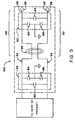
- an electrical schematic diagram of the first and second printed circuit boards 60 and 82 and the bus bars 32 and 34 is shown generally at 102 .
- the first printed circuit board 60 is electrically connected between filter portions 48 and 50 of the copper bus bars such that the first capacitor 64 is connected between the bus bars, the second capacitor 66 is connected between the first bus bar 32 and the signal ground, or chassis ground and the third capacitor 68 is connected between chassis ground and the second copper bus bar 34 , in a location between the first and second mounting studs 26 and 28 and the ferrite ring 80 .
- the second printed circuit board 82 is connected to the first and second bus bars 32 and 34 such that the sixth capacitor 88 is connected between the first and second bus bars 32 and 34 , the fourth capacitor 84 is connected between the first bus bar 32 and signal ground and the fifth capacitor 86 is connected between signal ground and the second bus bar 34 .
- the second printed circuit board 82 is electrically connected to the bus bars 32 and 34 at a location between the device to which the apparatus is connected and the ferrite ring 80 .
- the effect of the first and second printed circuit boards 60 and 82 is to provide first and second electromagnetic interference filter stages on opposite sides of the ferrite ring 80 on the bus bars 32 and 34 closely adjacent the first and second connectors. This reduces electromagnetic interference from being conducted by the connectors to equipment connected thereto.
- any inductance in connecting the capacitors to the bus bars is minimized.
- the short foil traces of the pads on the printed circuit boards have very minimal inductance.
- any loop area bounded by the bus bars is kept to a minimum and therefore, radiation of electromagnetic interference is kept to a minimum.
- first and second mounting studs 26 and 28 eliminates the possibility of wires connected to the studs from coming in contact with each other and eliminates the possibility of tools being dropped on the projection 16 and coming into contact with both the first and second studs at the same time thereby eliminating the possibility of an electrical short circuit between the studs.
- first and second mounting studs 26 and 28 extend generally parallel to the exterior surface 14 of the cover portion 12 and thus allow connecting wires to be connected to the studs such that the connecting wires extend at virtually any angle within 180 degrees range on the exterior surface 14 . This allows flexibility in mounting the apparatus to which the cover portion 12 is connected, thus increasing the versatility of the apparatus.
- the user connects first and second high current DC conductors to the substantially in-line first and second opposing studs 26 and 28 respectively on opposite sides respectively of the insulated terminal projection 16 connected to the base 14 securable to an electrical device.
- first and second bus bars 32 and 34 which extend closely adjacent each other inside the projection 16 and which terminate in the electrical device.
- Signals on the first and second bus bars are filtered to reduce electromagnetic interference by encircling the bus bars with a ferrite ring and capacitively coupling the first and second bus bars together and to a signal ground terminal of the electrical device, on each side of the ferrite ring.
- a first circuit board is urged against the first and second bus bars such that first and second pads on the first circuit board are in direct electrical contact with the first and second bus bars respectively.
Landscapes
- Shielding Devices Or Components To Electric Or Magnetic Fields (AREA)
- Details Of Connecting Devices For Male And Female Coupling (AREA)
- Connector Housings Or Holding Contact Members (AREA)
Applications Claiming Priority (2)
| Application Number | Priority Date | Filing Date | Title |
|---|---|---|---|
| US08/914,617 US6068513A (en) | 1997-08-19 | 1997-08-19 | DC connection method |
| US914617 | 1997-08-19 |
Publications (2)
| Publication Number | Publication Date |
|---|---|
| EP0910136A2 true EP0910136A2 (fr) | 1999-04-21 |
| EP0910136A3 EP0910136A3 (fr) | 2000-08-30 |
Family
ID=25434573
Family Applications (1)
| Application Number | Title | Priority Date | Filing Date |
|---|---|---|---|
| EP98306643A Withdrawn EP0910136A3 (fr) | 1997-08-19 | 1998-08-19 | Méthode de connection pour courant continu |
Country Status (3)
| Country | Link |
|---|---|
| US (1) | US6068513A (fr) |
| EP (1) | EP0910136A3 (fr) |
| CA (1) | CA2244470A1 (fr) |
Cited By (2)
| Publication number | Priority date | Publication date | Assignee | Title |
|---|---|---|---|---|
| US6984148B1 (en) | 2004-07-16 | 2006-01-10 | Xantrex Technology Inc. | Electrical connector apparatus and cover therefor |
| WO2009004385A1 (fr) * | 2007-07-03 | 2009-01-08 | Pilkington Group Limited | Réduction d'interférences hf pour des vitrages fonctionnels |
Families Citing this family (10)
| Publication number | Priority date | Publication date | Assignee | Title |
|---|---|---|---|---|
| JP4482782B2 (ja) * | 1999-12-16 | 2010-06-16 | 株式会社デンソー | 車両用交流発電機の制御装置 |
| FR2819678B1 (fr) * | 2001-01-12 | 2003-04-11 | Sagem | Circuit de filtrage, et dispositif d'alimentation de puissance equipe d'un tel circuit de filtrage |
| US7528579B2 (en) * | 2003-10-23 | 2009-05-05 | Schumacher Electric Corporation | System and method for charging batteries |
| USD522453S1 (en) | 2004-11-29 | 2006-06-06 | Xantrex International | Battery terminal |
| US20060158037A1 (en) * | 2005-01-18 | 2006-07-20 | Danley Douglas R | Fully integrated power storage and supply appliance with power uploading capability |
| US7274975B2 (en) * | 2005-06-06 | 2007-09-25 | Gridpoint, Inc. | Optimized energy management system |
| US20070203860A1 (en) * | 2006-02-24 | 2007-08-30 | Gridpoint, Inc. | Energy budget manager |
| US8103389B2 (en) | 2006-05-18 | 2012-01-24 | Gridpoint, Inc. | Modular energy control system |
| CN201285936Y (zh) * | 2008-09-16 | 2009-08-05 | 富士康(昆山)电脑接插件有限公司 | 线缆连接器组件 |
| US9622384B2 (en) * | 2011-11-22 | 2017-04-11 | Quantum Fuel Systems Llc | Fishtail packaging and cooling |
Family Cites Families (14)
| Publication number | Priority date | Publication date | Assignee | Title |
|---|---|---|---|---|
| US1359280A (en) * | 1918-10-10 | 1920-11-16 | Manhattan Electrical Supply Co | Detachable connector |
| US2174382A (en) * | 1934-10-04 | 1939-09-26 | Gen Electric | Electric discharge device and seal therefor |
| FR1198282A (fr) * | 1958-06-24 | 1959-12-07 | Dispositif de distribution de prise de courant électrique | |
| US3717805A (en) * | 1971-07-09 | 1973-02-20 | Basler Electric Co | Electrical power center for recreational vehicles |
| US4186339A (en) * | 1978-01-20 | 1980-01-29 | Curtis Instruments, Inc. | Method and apparatus for measuring current, especially useful in multi-ampere systems |
| DE3379308D1 (en) * | 1982-03-26 | 1989-04-06 | Feller Ag | Device for protecting an electrical apparatus against disturbances |
| US4872102A (en) * | 1986-04-28 | 1989-10-03 | Dimensions Unlimited, Inc. | D.C. to A.C. inverter having improved structure providing improved thermal dissipation |
| US5266055A (en) * | 1988-10-11 | 1993-11-30 | Mitsubishi Denki Kabushiki Kaisha | Connector |
| US5293145A (en) * | 1989-09-19 | 1994-03-08 | Onan Corporation | Switch battery charger with reduced electromagnetic emission |
| US5170336A (en) * | 1990-03-05 | 1992-12-08 | Dimensions Unlimited, Inc. | DC to AC inverter with improved forced air cooling method and apparatus |
| US5133668A (en) * | 1991-06-17 | 1992-07-28 | Brown Iv David C | Electrical connector apparatus |
| AU4639393A (en) * | 1992-06-16 | 1994-01-04 | Dill Systems Corp. | Magnetic circuits for communicating data |
| US5409401A (en) * | 1992-11-03 | 1995-04-25 | The Whitaker Corporation | Filtered connector |
| US5600550A (en) * | 1994-06-08 | 1997-02-04 | Progressive Dynamics, Inc. | Power converter for recreational vehicles and the like |
-
1997
- 1997-08-19 US US08/914,617 patent/US6068513A/en not_active Expired - Lifetime
-
1998
- 1998-08-05 CA CA002244470A patent/CA2244470A1/fr not_active Abandoned
- 1998-08-19 EP EP98306643A patent/EP0910136A3/fr not_active Withdrawn
Cited By (4)
| Publication number | Priority date | Publication date | Assignee | Title |
|---|---|---|---|---|
| US6984148B1 (en) | 2004-07-16 | 2006-01-10 | Xantrex Technology Inc. | Electrical connector apparatus and cover therefor |
| WO2009004385A1 (fr) * | 2007-07-03 | 2009-01-08 | Pilkington Group Limited | Réduction d'interférences hf pour des vitrages fonctionnels |
| US8189254B2 (en) | 2007-07-03 | 2012-05-29 | Pilkington Group Limited | RF interference reduction for functional glazings |
| EP3366467A1 (fr) * | 2007-07-03 | 2018-08-29 | Pilkington Group Limited | Réduction d'interférences rf pour des vitrages fonctionnels |
Also Published As
| Publication number | Publication date |
|---|---|
| EP0910136A3 (fr) | 2000-08-30 |
| US6068513A (en) | 2000-05-30 |
| CA2244470A1 (fr) | 1999-02-19 |
Similar Documents
| Publication | Publication Date | Title |
|---|---|---|
| CN201285936Y (zh) | 线缆连接器组件 | |
| US6024589A (en) | Power bus bar for providing a low impedance connection between a first and second printed circuit board | |
| TWI253212B (en) | Connector having a simple structure assuring a stable mounting operation | |
| CA2034804A1 (fr) | Connecteur pour circuits imprimes | |
| US6068513A (en) | DC connection method | |
| JPH0676894A (ja) | コネクタ | |
| WO1998006152A1 (fr) | Connecteur muni de dispositifs de circuit et d'indicateurs | |
| US5509812A (en) | Cable tap assembly | |
| US6960100B2 (en) | Grounding apparatus for an electronic module | |
| US3744001A (en) | Filter adaptor for printed circuit board connector | |
| US5197902A (en) | Termination adaptor connector device | |
| JPH04298099A (ja) | 電子機器の筐体 | |
| US5975923A (en) | Electrical appliance with a metal plate for a grounding device | |
| JPH0611282U (ja) | Catv用機器の接栓取付構造 | |
| JP2002354756A (ja) | エンコーダ付きモータ | |
| JPH01315212A (ja) | 分岐コネクタ | |
| JPH078960U (ja) | 電気部品の取付金具 | |
| CN222637830U (zh) | 一种电连接器 | |
| JPH10261455A (ja) | シールドコネクタ | |
| JP3006543B2 (ja) | 給電ユニット | |
| US7371085B2 (en) | Connector attachment structure for electronic apparatus | |
| JPS59220009A (ja) | 自動車用配線装置 | |
| JP3317627B2 (ja) | コネクタ及びコネクタ付電子ユニット | |
| JPS6038312Y2 (ja) | 筐体装置 | |
| CN213460339U (zh) | Emc功能型连接器 |
Legal Events
| Date | Code | Title | Description |
|---|---|---|---|
| PUAI | Public reference made under article 153(3) epc to a published international application that has entered the european phase |
Free format text: ORIGINAL CODE: 0009012 |
|
| AK | Designated contracting states |
Kind code of ref document: A2 Designated state(s): DE FR GB |
|
| AX | Request for extension of the european patent |
Free format text: AL;LT;LV;MK;RO;SI |
|
| RAP1 | Party data changed (applicant data changed or rights of an application transferred) |
Owner name: STATPOWER TECHNOLOGIES PARTNERSHIP |
|
| PUAL | Search report despatched |
Free format text: ORIGINAL CODE: 0009013 |
|
| AK | Designated contracting states |
Kind code of ref document: A3 Designated state(s): AT BE CH CY DE DK ES FI FR GB GR IE IT LI LU MC NL PT SE |
|
| AX | Request for extension of the european patent |
Free format text: AL;LT;LV;MK;RO;SI |
|
| 17P | Request for examination filed |
Effective date: 20010129 |
|
| RAP1 | Party data changed (applicant data changed or rights of an application transferred) |
Owner name: XANTREX INTERNATIONAL |
|
| AKX | Designation fees paid |
Free format text: DE FR GB |
|
| RAP1 | Party data changed (applicant data changed or rights of an application transferred) |
Owner name: XANTREX INTERNATIONAL |
|
| 17Q | First examination report despatched |
Effective date: 20010731 |
|
| STAA | Information on the status of an ep patent application or granted ep patent |
Free format text: STATUS: THE APPLICATION IS DEEMED TO BE WITHDRAWN |
|
| 18D | Application deemed to be withdrawn |
Effective date: 20011212 |