EP0910145A1 - Cadre pour un couvercle d'une boíte - Google Patents
Cadre pour un couvercle d'une boíte Download PDFInfo
- Publication number
- EP0910145A1 EP0910145A1 EP98117454A EP98117454A EP0910145A1 EP 0910145 A1 EP0910145 A1 EP 0910145A1 EP 98117454 A EP98117454 A EP 98117454A EP 98117454 A EP98117454 A EP 98117454A EP 0910145 A1 EP0910145 A1 EP 0910145A1
- Authority
- EP
- European Patent Office
- Prior art keywords
- frame
- side wall
- joining section
- projection
- recess
- Prior art date
- Legal status (The legal status is an assumption and is not a legal conclusion. Google has not performed a legal analysis and makes no representation as to the accuracy of the status listed.)
- Granted
Links
- 238000010616 electrical installation Methods 0.000 claims abstract description 5
- 238000005304 joining Methods 0.000 claims description 31
- 230000013011 mating Effects 0.000 abstract 1
- 210000002105 tongue Anatomy 0.000 abstract 1
- 239000000463 material Substances 0.000 description 7
- 238000000034 method Methods 0.000 description 4
- 239000011261 inert gas Substances 0.000 description 2
- 238000004519 manufacturing process Methods 0.000 description 2
- 210000001331 nose Anatomy 0.000 description 2
- 238000003466 welding Methods 0.000 description 2
- 230000005540 biological transmission Effects 0.000 description 1
- 230000001419 dependent effect Effects 0.000 description 1
- 238000007598 dipping method Methods 0.000 description 1
- 238000009434 installation Methods 0.000 description 1
- 238000003860 storage Methods 0.000 description 1
Images

Classifications
-
- H—ELECTRICITY
- H02—GENERATION; CONVERSION OR DISTRIBUTION OF ELECTRIC POWER
- H02G—INSTALLATION OF ELECTRIC CABLES OR LINES, OR OF COMBINED OPTICAL AND ELECTRIC CABLES OR LINES
- H02G3/00—Installations of electric cables or lines or protective tubing therefor in or on buildings, equivalent structures or vehicles
- H02G3/02—Details
- H02G3/08—Distribution boxes; Connection or junction boxes
- H02G3/18—Distribution boxes; Connection or junction boxes providing line outlets
- H02G3/185—Floor outlets and access cups
Definitions
- the invention relates to a frame for a cassette cover, in particular a junction or branch box of an underfloor electrical installation duct, consisting of several, too a ring composed side wall parts, each At least one oriented in the direction of leadership of the frame Guide wall, a projecting transversely to the guide direction of the frame Have assembly element and a joining section.
- cassette frames have so far been dependent on Installation space and the material from which the individual parts are made are, with the help of different, more complex and thus expensive joining techniques, such as inert gas welding or blind rivets, from the individual parts to one Pieces put together.
- the present invention is based on the object to provide a frame of the type mentioned at the beginning, which is easier and more flexible to manufacture.
- a first joining section at least one side wall part at least one freely protruding, extending outward projection and in one second joining section of an adjacent side wall part recess corresponding to the dimensions of the projection provided, into which the projection can be positively fitted.
- Such side wall parts can be used independently of the one used Detachable material and without complex joining techniques put together into a frame, the frame a has equivalent stability compared to known frames. The manufacturing process of such a frame largely with different materials used remain unchangeable. Furthermore, side wall parts can consist of almost any materials can be assembled.
- all side wall parts have a first joining wall section, each with an identical projection and a second joining section, each with identical, matching recess on the projection.
- the projection in a part of the respective assembly element first joining section and the recess in one to the respective Mounting element belonging part of the second joining section arranged and point in the guide direction of the frame constant cross-sectional areas. This results in oriented parallel to the direction of the frame Contact areas between the projection and recess, the one exact positioning of the side wall parts transverse to the guide direction of the frame. Furthermore, the mentioned contact surfaces in an advantageous manner circumferential forces transferred transversely to the direction of the frame.
- the assembly elements arranged in the foot area of the frame and form a circumferential support flange. Such an arrangement ensures a particularly stable storage of the frame on a flat support surface.
- Fig. 1 is a pull socket 3 for an underfloor electrical installation duct shown with a cassette cover 2 is provided, in a frame according to the invention 1 is stored.
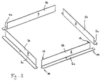
- the frame 1 consists of four side wall parts 4, 5, 6, 7 that form a ring with a square base are composed.
- Each of the four side wall parts 4 to 7 is approximately shaped as an L-profile, so that with each side wall part two sections in the form of a guide wall 4b, 5b, 6b and 7b as well as a mounting element serving foot part 4a, 5a, 6a and 7a result.
- the guide walls 4b to 7b are parallel, the foot parts 4a to 7a oriented perpendicular to a guide direction F of the frame. Since in the embodiment shown in the figures all side wall parts are largely identical, the side wall part 6 is explained by way of example below, which is interchangeable with any other side wall part.
- the side wall part 6 is adjacent to the adjacent side wall part 7 a first joining section 10, 12 and adjacent to the adjacent side wall part 5 a second joining section 14, 16 on, as can be seen from Fig. 3. With help this joining sections, the side wall part 6 can be detached plug together with the adjacent side wall parts 7 and 5, such a connector, the rest is shown separately in Fig. 2, between a first and a second joining section different from this can be realized is.
- a projection 11 projecting freely from the foot part 6a is provided, the bulbous across the direction of the frame is, so that there is a constriction 11a.
- a recess 15 is provided, the corresponds to the dimensions of the projection 11 and into which Projection 11 can be used with a predetermined game. A relatively little play may even be a frictional Fixing the side wall parts against each other. Both the Projection 11 and the recess 15 point in the guide direction the frame has a constant cross-sectional area so that the projection 11 in the guide direction of the frame slidably mounted in the recess 15 and the other sufficient contact area for power transmission between Projection and recess is provided.
- gear elements in the form of several recesses 13 are gear elements in the form of several recesses 13 provided. These recesses 13 extend transversely through the guide wall 6b and form a receptacle for the side wall 7b protruding, also as gear elements serving noses 17.
- the height dimensions of the one above the other arranged recesses 13 are increasing from bottom to top executed so that the height h of the respective recess 13 is the same size or slightly larger than the sum of the Height 1 of the associated nose 17 and the thickness t of the foot part 7a.
- the connector described is at all four corners of the Frame 1 provided and allows the easy, easy to be solved joining the four side parts 4 to 7 to the Frame 1, the four foot parts 4a to 7a after joining form a circumferential support flange, which because of the positive Engagement of all projections 11 in the associated Recesses 15 in the foot area of the frame 1 a stable Ring forms.
- a likewise detachable fastening of the frame 1 on the junction box 3 is therefore, as can be seen from Fig. 1, with some few screws 18 are provided.
Landscapes
- Engineering & Computer Science (AREA)
- Architecture (AREA)
- Civil Engineering (AREA)
- Structural Engineering (AREA)
- Casings For Electric Apparatus (AREA)
- Holding Or Fastening Of Disk On Rotational Shaft (AREA)
- Connection Or Junction Boxes (AREA)
- Connector Housings Or Holding Contact Members (AREA)
Applications Claiming Priority (2)
| Application Number | Priority Date | Filing Date | Title |
|---|---|---|---|
| DE29718202U DE29718202U1 (de) | 1997-10-14 | 1997-10-14 | Rahmen für einen Kassettendeckel |
| DE29718202U | 1997-10-14 |
Publications (2)
| Publication Number | Publication Date |
|---|---|
| EP0910145A1 true EP0910145A1 (fr) | 1999-04-21 |
| EP0910145B1 EP0910145B1 (fr) | 2001-11-21 |
Family
ID=8047207
Family Applications (1)
| Application Number | Title | Priority Date | Filing Date |
|---|---|---|---|
| EP98117454A Expired - Lifetime EP0910145B1 (fr) | 1997-10-14 | 1998-09-15 | Cadre pour un couvercle d'une boíte |
Country Status (3)
| Country | Link |
|---|---|
| EP (1) | EP0910145B1 (fr) |
| DE (2) | DE29718202U1 (fr) |
| ES (1) | ES2165650T3 (fr) |
Families Citing this family (5)
| Publication number | Priority date | Publication date | Assignee | Title |
|---|---|---|---|---|
| DE20102176U1 (de) * | 2001-02-02 | 2001-05-10 | Albert Ackermann GmbH & Co. KG, 51643 Gummersbach | Zug- oder Abzweigdose für einen Unterflurelektroinstallationskanal |
| DE20319362U1 (de) | 2003-12-11 | 2004-03-04 | Novar Gmbh | Kassettendeckel |
| DE102010022640B4 (de) * | 2010-06-04 | 2012-08-30 | Puk-Werke Kg Kunststoff-Stahlverarbeitung Gmbh & Co | Anschlussbodendose |
| DE102014203622A1 (de) * | 2014-02-27 | 2015-08-27 | Obo Bettermann Gmbh & Co. Kg | Unterflurkassette und Verfahren zum Einbauen einer Unterflurkassette |
| EP2924835A1 (fr) * | 2014-03-27 | 2015-09-30 | Vergokan | Élément de coffrage destiné à un système de boîte de sol |
Citations (1)
| Publication number | Priority date | Publication date | Assignee | Title |
|---|---|---|---|---|
| DE7112816U (de) * | 1971-04-02 | 1971-06-24 | Ackermann A | Deckel mit Teppichschutzrahmen fur eine als Zugdose ausgebildete Fußboden dose |
Family Cites Families (2)
| Publication number | Priority date | Publication date | Assignee | Title |
|---|---|---|---|---|
| DE1908480C3 (de) * | 1969-02-20 | 1979-04-05 | Siemens Ag, 1000 Berlin Und 8000 Muenchen | Bodendose für elektrische Unterflur-Installationen mit einem Rahmen, der einen Deckel aufnimmt |
| NL9201206A (nl) * | 1992-07-06 | 1994-02-01 | Geel Syst Bv | Montageraam. |
-
1997
- 1997-10-14 DE DE29718202U patent/DE29718202U1/de not_active Expired - Lifetime
-
1998
- 1998-09-15 ES ES98117454T patent/ES2165650T3/es not_active Expired - Lifetime
- 1998-09-15 EP EP98117454A patent/EP0910145B1/fr not_active Expired - Lifetime
- 1998-09-15 DE DE59802697T patent/DE59802697D1/de not_active Expired - Lifetime
Patent Citations (1)
| Publication number | Priority date | Publication date | Assignee | Title |
|---|---|---|---|---|
| DE7112816U (de) * | 1971-04-02 | 1971-06-24 | Ackermann A | Deckel mit Teppichschutzrahmen fur eine als Zugdose ausgebildete Fußboden dose |
Also Published As
| Publication number | Publication date |
|---|---|
| EP0910145B1 (fr) | 2001-11-21 |
| DE29718202U1 (de) | 1997-12-04 |
| ES2165650T3 (es) | 2002-03-16 |
| DE59802697D1 (de) | 2002-02-21 |
Similar Documents
| Publication | Publication Date | Title |
|---|---|---|
| DE69702930T2 (de) | Kartonschachtel mit zentrierlaschen und zuschnitt für ihre herstellung | |
| DE69604603T2 (de) | Sockel für einen Schaltschrank oder dergleichen und Schrank mit einen solchen Sockel | |
| DE69121270T2 (de) | Zweiteilige Buchseneinheit für modularen Steckeraufbau | |
| DE2811691C2 (de) | Gitterrost | |
| DE2617983A1 (de) | Palette | |
| DE69223032T2 (de) | Stütze-/Befestigungsbau für IC-Kartenverbinder | |
| DE2242569A1 (de) | Gehaeuse fuer elektrisch betriebene schreibmaschinen und aehnliche maschinen | |
| DE3328746C2 (fr) | ||
| EP0910145B1 (fr) | Cadre pour un couvercle d'une boíte | |
| EP0040409B1 (fr) | Tableau mosaique à face frontale close | |
| DE68907727T2 (de) | Kanalverbindungsvorrichtung. | |
| EP0918450A2 (fr) | Boítier plastique pour composants électriques ou électroniques | |
| EP0013999B1 (fr) | Charnière | |
| DE2546087C2 (de) | Kastenelemente für eine isolierstoff-gekapselte Schaltanlage mit Schalt-, Steuer- und Regeleinrichtung | |
| DE69321081T2 (de) | Gehäuse für ein tragbares Miniaturgerät | |
| DE4018141A1 (de) | Unterfahrbare transportpalette | |
| DE19745181C2 (de) | Bauteil für HF-dichte Behältnisse | |
| DE2031794C3 (de) | Akkumulator | |
| DE2105568A1 (de) | Modellbaustein | |
| DE3149054A1 (de) | Lueftungsgitter | |
| WO1990003678A1 (fr) | Boitier pour un commutateur en charge moyenne tension a isolation par gaz | |
| DE4025630C2 (fr) | ||
| DE10345054A1 (de) | Faltbehälter | |
| EP0465492B1 (fr) | Porte-bouteilles separable | |
| DE3342486C1 (de) | Kastenförmiges Abschirmgehäuse |
Legal Events
| Date | Code | Title | Description |
|---|---|---|---|
| PUAI | Public reference made under article 153(3) epc to a published international application that has entered the european phase |
Free format text: ORIGINAL CODE: 0009012 |
|
| AK | Designated contracting states |
Kind code of ref document: A1 Designated state(s): DE ES FR GB |
|
| AX | Request for extension of the european patent |
Free format text: AL;LT;LV;MK;RO;SI |
|
| RTI1 | Title (correction) | ||
| 17P | Request for examination filed |
Effective date: 19990525 |
|
| AKX | Designation fees paid |
Free format text: DE ES FR GB |
|
| GRAG | Despatch of communication of intention to grant |
Free format text: ORIGINAL CODE: EPIDOS AGRA |
|
| 17Q | First examination report despatched |
Effective date: 20010123 |
|
| GRAG | Despatch of communication of intention to grant |
Free format text: ORIGINAL CODE: EPIDOS AGRA |
|
| GRAH | Despatch of communication of intention to grant a patent |
Free format text: ORIGINAL CODE: EPIDOS IGRA |
|
| GRAH | Despatch of communication of intention to grant a patent |
Free format text: ORIGINAL CODE: EPIDOS IGRA |
|
| GRAA | (expected) grant |
Free format text: ORIGINAL CODE: 0009210 |
|
| AK | Designated contracting states |
Kind code of ref document: B1 Designated state(s): DE ES FR GB |
|
| REG | Reference to a national code |
Ref country code: GB Ref legal event code: IF02 |
|
| REF | Corresponds to: |
Ref document number: 59802697 Country of ref document: DE Date of ref document: 20020221 |
|
| REG | Reference to a national code |
Ref country code: ES Ref legal event code: FG2A Ref document number: 2165650 Country of ref document: ES Kind code of ref document: T3 |
|
| GBT | Gb: translation of ep patent filed (gb section 77(6)(a)/1977) |
Effective date: 20020221 |
|
| ET | Fr: translation filed | ||
| PLBE | No opposition filed within time limit |
Free format text: ORIGINAL CODE: 0009261 |
|
| STAA | Information on the status of an ep patent application or granted ep patent |
Free format text: STATUS: NO OPPOSITION FILED WITHIN TIME LIMIT |
|
| 26N | No opposition filed | ||
| PGFP | Annual fee paid to national office [announced via postgrant information from national office to epo] |
Ref country code: ES Payment date: 20080922 Year of fee payment: 11 |
|
| PGFP | Annual fee paid to national office [announced via postgrant information from national office to epo] |
Ref country code: FR Payment date: 20080917 Year of fee payment: 11 |
|
| PGFP | Annual fee paid to national office [announced via postgrant information from national office to epo] |
Ref country code: GB Payment date: 20080922 Year of fee payment: 11 |
|
| GBPC | Gb: european patent ceased through non-payment of renewal fee |
Effective date: 20090915 |
|
| REG | Reference to a national code |
Ref country code: FR Ref legal event code: ST Effective date: 20100531 |
|
| PG25 | Lapsed in a contracting state [announced via postgrant information from national office to epo] |
Ref country code: FR Free format text: LAPSE BECAUSE OF NON-PAYMENT OF DUE FEES Effective date: 20090930 |
|
| PG25 | Lapsed in a contracting state [announced via postgrant information from national office to epo] |
Ref country code: GB Free format text: LAPSE BECAUSE OF NON-PAYMENT OF DUE FEES Effective date: 20090915 |
|
| REG | Reference to a national code |
Ref country code: ES Ref legal event code: FD2A Effective date: 20110718 |
|
| PG25 | Lapsed in a contracting state [announced via postgrant information from national office to epo] |
Ref country code: ES Free format text: LAPSE BECAUSE OF NON-PAYMENT OF DUE FEES Effective date: 20110706 |
|
| PG25 | Lapsed in a contracting state [announced via postgrant information from national office to epo] |
Ref country code: ES Free format text: LAPSE BECAUSE OF NON-PAYMENT OF DUE FEES Effective date: 20090916 |
|
| PGFP | Annual fee paid to national office [announced via postgrant information from national office to epo] |
Ref country code: DE Payment date: 20160929 Year of fee payment: 19 |
|
| REG | Reference to a national code |
Ref country code: DE Ref legal event code: R119 Ref document number: 59802697 Country of ref document: DE |
|
| PG25 | Lapsed in a contracting state [announced via postgrant information from national office to epo] |
Ref country code: DE Free format text: LAPSE BECAUSE OF NON-PAYMENT OF DUE FEES Effective date: 20180404 |