EP0910179B1 - Verfahren und Gerät zür Verstärkung von Mehrkanalsignalen von Raumfahrzeug - Google Patents
Verfahren und Gerät zür Verstärkung von Mehrkanalsignalen von Raumfahrzeug Download PDFInfo
- Publication number
- EP0910179B1 EP0910179B1 EP98402591A EP98402591A EP0910179B1 EP 0910179 B1 EP0910179 B1 EP 0910179B1 EP 98402591 A EP98402591 A EP 98402591A EP 98402591 A EP98402591 A EP 98402591A EP 0910179 B1 EP0910179 B1 EP 0910179B1
- Authority
- EP
- European Patent Office
- Prior art keywords
- signals
- frequency
- channels
- input signals
- sets
- Prior art date
- Legal status (The legal status is an assumption and is not a legal conclusion. Google has not performed a legal analysis and makes no representation as to the accuracy of the status listed.)
- Expired - Lifetime
Links
- 238000000034 method Methods 0.000 title claims description 11
- 230000003321 amplification Effects 0.000 claims description 28
- 238000003199 nucleic acid amplification method Methods 0.000 claims description 28
- 238000004891 communication Methods 0.000 claims description 8
- 238000010586 diagram Methods 0.000 description 6
- 210000001565 alc Anatomy 0.000 description 5
- 230000010287 polarization Effects 0.000 description 5
- 230000005540 biological transmission Effects 0.000 description 4
- 238000000926 separation method Methods 0.000 description 2
- 230000015572 biosynthetic process Effects 0.000 description 1
- 239000000969 carrier Substances 0.000 description 1
- 238000006243 chemical reaction Methods 0.000 description 1
- 239000002131 composite material Substances 0.000 description 1
- 238000001914 filtration Methods 0.000 description 1
- 239000003607 modifier Substances 0.000 description 1
- 239000007787 solid Substances 0.000 description 1
- 238000010561 standard procedure Methods 0.000 description 1
Images


Classifications
-
- H—ELECTRICITY
- H04—ELECTRIC COMMUNICATION TECHNIQUE
- H04B—TRANSMISSION
- H04B7/00—Radio transmission systems, i.e. using radiation field
- H04B7/14—Relay systems
- H04B7/15—Active relay systems
- H04B7/185—Space-based or airborne stations; Stations for satellite systems
- H04B7/1851—Systems using a satellite or space-based relay
- H04B7/18515—Transmission equipment in satellites or space-based relays
Definitions
- This invention relates to communications spacecraft, and more particularly to a low cost method and apparatus for satellite amplification of communication signals within different channels (satellite transponders) that are separate from each other in frequency.
- the standard technique for transmitting multiple signal channels from a single satellite is to provide a separate high power amplifier dedicated to each channel.
- 32 active amplifiers would be used for a frequency plan covering 32 channels. This works well for large coverage areas, or smaller coverage areas with high power requirements.
- this results in excess output power capacity and weight when amplifiers with standard power ratings are used, and the amplifiers will be required to operate at less than efficient levels.
- High power amplifiers typically weigh on the order of 5 kg each, so a requirement for 32 separate amplifiers adds significantly to the total payload weight. At present each amplifier costs on the order of $250,000 and adds roughly another $150,000 to launch costs. The direct and indirect costs of amplifiers for a satellite with 32 downlink channels can thus exceed $10,000,000.
- a method used on occasion for channel amplification has been to route multiple channels that are adjacent in frequency through a single amplifier. This is used for low power applications, such as the input receiver of a payload, but is rarely useful for high power amplification due to the intermodulation distortion that results when the amplifier is operated near saturation. To reduce the intermodulation components to acceptable levels the amplifier may have to be operated closer to its linear region, resulting in reduced DC power consumption efficiency. Even if the possibility of intermodulation distortion is accepted along with a more expensive DC power consumption, the individual channels cannot be routed to different downlink antennas as is frequently desirable, particularly for a spot beam application.
- the present invention seeks to provide a method and apparatus to more efficiently amplify multi-channel satellite signals while avoiding disruptive intermodulation distortion and achieving both lower costs and reduced payload weight.
- the selected set of channel signals for each amplifier are combined prior to amplification, with the combined signal amplified by the common amplifier.
- the channels within each set are preferably separated from each other after common amplification, with the various channels broadcast either separately from individual antennas or in combination with other channels (which need not have been included in its input set) from the same downlink antenna.
- Different amplifiers can also be used for channels with different polarizations, and additional amplifiers can be dedicated to single channels with higher powers. The final result is a system that costs and weighs significantly less than one utilizing a separate amplifier for each channel.
- FIG. 1 illustrates the primary application for the invention, which is the satellite broadcast of local service direct television programming, preferably together with larger regional broadcasts.
- the invention is not limited to television signals, and is applicable to spacecraft communications in general.
- An uplink beam 40 is transmitted from a ground station 42 on the earth's surface 44 to an uplink antenna 46 on an orbiting satellite 48.
- the uplink signal will generally include numerous different channels (frequency bands).
- the satellite may also receive additional uplink beams on the same or additional uplink antennas.
- the uplink beams are processed by the satellite circuitry and transformed to a series of downlink signals, which are transmitted back to earth as broadcast beams 50a, 50b from respective downlink antennas 52a, 52b. More than one beam will normally be transmitted from each antenna, with the beam directionalities determined by the positions of the antenna feedhorns which are excited by each channel, relative to the antenna reflectors.
- Some of the beams can be smaller "spot" beams for local direct television service under the International Telecommunications Union Broadcast Satellite Service (BSS) category, while other beams can be for larger regional service areas under the Fixed Satellite Service (FSS) category.
- BSS International Telecommunications Union Broadcast Satellite Service
- FSS Fixed Satellite Service
- the type of feedhorn employed and the size of the antenna reflector determine the size of each beam.
- the amplification of multiple channels by a single amplifier has been limited to relatively low power applications, generally less than 50 Watts, because of cross-modulation distortion between the channels in commonly available amplifiers with less than 150 Watt capacity.
- the third order intermodulation products generally lead to the most severe distortion.
- Third order intermodulation products generated by two adjacent channels are illustrated in the frequency plot of FIG. 2a.
- successive channels that are adjacent to each other in frequency are identified by successive odd numbers; even numbers are used for channels within the same frequency band but with an opposite polarization.
- a broadcast channel with a frequency band of 25.5 MHz is used, and is separated from the next adjacent channel by 3 MHz.
- Adjacent channels 1 and 3 are illustrated in FIG. 2a, with channel 1 extending between a low frequency L1 and a high frequency H1, and channel 3 extending between a low frequency L3 and a high frequency H3.
- the lower frequency third order intermodulation product 54 extends from a low frequency L1-(H3-L1) to a high frequency of H1-(L3-H1)
- the higher frequency third order intermodulation product 56 extends from a low frequency L3+(L3-H1) to a high frequency of H3 +(H3-L1).
- the third order intermodulation products overlap with each of the channels, and thus introduce a significant amount of distortion into the channel downlink broadcast.
- two or more lower power channels are amplified by a single common amplifier, thus reducing the total number of required amplifiers and yielding significant cost and weight savings, by a careful selection of the channels to be amplified in common.
- Their frequency bands are mutually discrete and sufficiently separated in frequency that their third order intermodulation products do not substantially overlap in frequency with any of the other channels to be amplified by the same amplifier. While third order intermodulation products are still generated, they are separated in frequency from the channels being amplified and can be filtered out, thus removing the most severe distortion components from the signals transmitted back to earth.
- FIG. 2b The frequency separation employed by the invention is illustrated in FIG. 2b, in which channels 1 and 5 are selected for common amplification. Since channels 1 and 5 are separated by channel 3, there is a frequency gap of 31.5 MHz (3 + 25.5 + 3) between them.
- the lower frequency third order intermodulation product 58 which extends from L1-(H5-L1) to H1-(L5-H1), is spaced in frequencies below channel 1;
- the higher frequency third order intermodulation product 60 which extends from L5+(L5-H1) to H5+(H5-L1), is similarly spaced in frequency above channel 5. This allows channels 1 and 5 to be amplified together and their third order intermodulation products filtered out before being broadcast from the satellite.
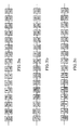
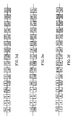
- FIGs. 3a-3f are frequency plans which illustrate various channel combinations that can be realized for common high power amplification in accordance with the invention, spaced sufficiently apart in frequency that their third order intermodulation products do not overlap with the channel frequency bands within a given amplifier.
- Each frequency plan includes 32 channels, with 16 channels having one polarization (say vertical or right hand circular), and the other 16 channels occupying the same frequency bands but having the opposite polarization (horizontal or left hand circular) so that they do not interfere with the first 16 channels.
- polarization say vertical or right hand circular
- the opposite polarization horizontal or left hand circular
- FIGs. 3a-3f the channels to be amplified in common with each other are designated by the same letter.
- channels 1 and 5 are marked A to signify that they can be amplified together (this is the example of FIG. 2b).
- channels 3 and 7, 2 and 6, and 4 and 8 are respectively marked B, C and D to signify that they can also be combined for common amplifications.
- FIG. 3b illustrates other two-channel combinations, such as more widely spaced channels 1 and 7 or 4 and 10, or channels with opposite polarizations such as 3 and 8, 2 and 5, or 6 and 9.
- the number of channels that can be combined for common amplification is not limited to two. A greater number of channels can be combined, as long as the third order intermodulation products produced by any two of the channels do not overlap in frequency with any of the channels in the set.
- FIG. 3c Various three-channel combinations are illustrated in FIG. 3c, including channels 1, 5 and 13, channels 2, 10 and 14, and channels 4, 8 and 15.
- FIG. 3d illustrates a greater channel separation, with channels 1, 7 and 17 selected as the set for common amplification.
- FIG. 3e shows channel combinations 1, 9, 13, 21 and 2, 12, 16, 28, and FIG. 3f which shows channel combination 1, 5, 13, 29.
- FIG. 3f shows channel combination 1, 5, 13, 29.
- a common amplification of more than four different channels would require a larger total number of channel frequency bands.
- FIG. 4 is a simplified block diagram of on-board satellite circuitry that can be used to implement the invention. Three circuits are shown. The first (62) is for processing a single channel, the second (64) is for processing multiple channels with common amplifiers and transmitting the different channels from individual downlink antennas, and a third circuit (66) which combines different channels for both amplification and downlink transmission, but in different combinations.
- the first circuit 62 receives an uplink signal via uplink antenna 68a and processes it in a bandpass filter rejects signals outside that band, including the downlink transmission frequencies.
- the filtered input signal is then processed through a receiver 72a, which includes a broadband low noise amplifier and a frequency converter that converts the signal from its uplink to its downlink frequency band.
- the channel signal at its downlink frequency band is processed by a conventional pre-amplification channel control unit with automatic level control(ALC) 74a and/or a linearizer 75a, and then by a high power amplifier 76a that is generally implemented as either a traveling wave tube or a solid state power amplifier.
- the amplified signal is filtered by a broadband bandpass filter 78a which rejects the uplink frequency to prevent energy from getting back into the receiver, and is then transmitted to earth as a broadcast beam from downlink antenna 80a.
- circuit 64 separate channels are combined for high power amplification.
- the uplink channel signals are received by an uplink antenna 68b, with downlink frequencies removed by bandpass filter 70b and low noise amplification with conversion to downlink frequency performed by receiver 72b.
- channels 1, 3, 5 and 7 are all received by antenna 68b. These channels are separated from each other by a hybrid divider 82 and a set of input filters 84 which divide the input signal into its separate channels. Channels 1 and 5 are then combined with each other, as are channels 3 and 7. Because signal loss is not a particular concern at the low power' levels involved at this point, the signal combining can be accomplished by simple hybrid combiners 86.
- the combined channel signals are then pre-amplified, preferably automatic level controlled by ALCs 74b and/or linearized by linearizers 75b for instances in which the uplink signals originate from a common ground station. However, if the uplink signals originate from different ground locations, a separate ALC 74b' and/or linearizer 75b' is preferably inserted into each individual channel path prior to the hybrid combiners 86, as indicated in dashed lines.
- the combined channels 1 and 5 are now amplified by high power amplifier 76b1, while the combined channels 3 and 7 are amplified by high power amplifier 76b2.
- These amplifiers are preferably selected to have somewhat higher power ratings than the combined powers of their respective channels to avoid saturation and operate more efficiently, but are not so large as to add unnecessary surplus capacity.
- the combined channel signals are again separated into individual channels, preferably by microwave output channel filters 88 connected to perform a demultiplex 88 formation which incorporate channel bandpass filters. This generates discrete channel outputs while at the same time providing an additional refection of unwanted intermodulation products generated in the amplifiers 76b.
- Each individual channel downlink signal is then transmitted by a respective downlink antenna 80b.
- the circuit 66 which combines channels 2, 6 and 4, 8 for common amplification is essentially similar to circuit 64 for channels 1, 3, 5 and 7 up to the point of downlink transmission, and similar reference numbers are used for circuit 66 as for circuit 64, with the "b" reference number modifier changed to "c" and a prime added to reference numbers that are used only for circuit 64 and not circuit 62.
- the separate channel signals are combined with one or more channels in microwave combining filters 90, known as output multiplexers, whose outputs are then routed to respective downlink antennas 80c.
- the output bandpass filters could be located after the combining filters 90, as indicated in dashed lines by blocks 78c'.
- the relative usable output power level of each individual carrier is controlled by the ALC output set points when the input channel signals are received from different uplink sites.
- the relative output power level of each individual carrier is controlled by the relative uplink power in each channel from that common site.
- the relative input power levels required are not the same as the resulting output power levels for unbalanced outputs, due to the non-linear characteristics of the high power amplifiers.
- a linearizer can be added before the high power amplifiers. This function can be included with or without the ALC function.
- Standard high power amplifier sizes generally range from 50w to 150w, whereas the beam powers required for direct television satellite broadcasts are generally in the range of about 17w-130w.
- a standard amplifier can thus be used to amplify two or more lower power beams in common. Although this reduces the effective amplify capacity of nonlinear amplifiers by about 1.5db, the reslting cost savings more than compensate for the power loss.
Landscapes
- Engineering & Computer Science (AREA)
- Physics & Mathematics (AREA)
- Astronomy & Astrophysics (AREA)
- Aviation & Aerospace Engineering (AREA)
- General Physics & Mathematics (AREA)
- Computer Networks & Wireless Communication (AREA)
- Signal Processing (AREA)
- Radio Relay Systems (AREA)
- Amplifiers (AREA)
Claims (8)
- Methode zur Verstärkung von Signalen für Raumfahrzeug-Sender aus einer Vielzahl von Eingangssignalen innerhalb verschiedener entsprechender Frequenzbänder, wobei mindestens einige Gruppen der besagten Eingangssignale Intermodulationsprodukte dritter Ordnung haben, deren Frequenz mindestens einige der besagten Eingangssignale überlappt, wobei die besagte Methode dadurch gekennzeichnet ist, dass sie folgende Schritte umfasst:Auswahl von mehreren Gruppen (1, 5; 3, 7) der besagten Eingangssignale, wobei die Eingangssignale jeder Gruppe Frequenzbänder haben, die beiderseits diskret sind und deren Frequenz ausreichend getrennt ist, so dass die Frequenz ihrer Intermodulationsprodukte dritter Ordnung (58, 65) nicht wesentlich mit einem beliebigen der anderen Eingangssignale in der gleichen Gruppe überlappt und dieausgewählten Gruppen der Eingangssignale mit einem unterschiedlichen üblichen Verstärker (76b1, 76b2) für jede Gruppe verstärkt werden.
- Methode des Anspruchs 1, bei der die Eingangssignale innerhalb jeder ausgewählten Signalgruppe vor der Verstärkung kombiniert werden und die kombinierten Signale durch ihre entsprechenden Verstärker verstärkt werden.
- Die Methode des Anspruchs 2 beinhaltet ferner den Schritt der Trennung der Eingangssignale untereinander innerhalb jeder ausgewählten Signalgruppe nach der Verstärkung.
- Die Methode des Anspruchs 3 beinhaltet ferner den Schritt, mindestens einige der getrennten und verstärkten Signale zu kombinieren.
- Ein Signalverstärkungssystem für Raumfahrzeugkommunikationen zur Verstärkung von Signalen aus einer Vielzahl von Eingangskommunikationssignalen innerhalb verschiedener entsprechender Frequenzbänder, wobei zumindest einige Gruppen der besagten Eingangssignale Intermodulationsprodukte dritter Ordnung haben, deren Frequenz mit mindestens einigen der besagten Eingangssignale überlappt und dieses System dadurch gekennzeichnet ist, dass es Folgendes umfasst:eine Vielzahl von Signalübersetzern (86), die angeschlossen sind für die Kombination entsprechender Gruppen (1, 5; 3, 7) der besagten Eingangssignale, deren Frequenzbänder beiderseits diskret und ausreichend getrennt sind, so dass die Frequenz ihrer Intermodulationsprodukte dritter Ordnung (58, 65) nicht wesentlich mit einem beliebigen der anderen Eingangssignale in der gleichen Gruppe überlappt undentsprechende Verstärker (76b1, 76b2), die angeschlossen sind, um die besagten Gruppen der Eingangssignale separat zu verstärken.
- Das Signalverstärkungssystem des Anspruchs 5, beinhaltet ferner entsprechende Signaltrenner (88, 88'), die angeschlossen sind, um nach der Verstärkung das Eingangssignal innerhalb der besagten Signalgruppen untereinander zu trennen.
- Das Signalverstärkungssystem des Anspruchs 6 beinhaltet ferner zumindest einen Ausgangssignalübersetzer (90), der angeschlossen ist, um zumindest einige der besagten getrennten und verstärkten Signale zu kombinieren.
- Das Signalverstärkungssystem des Anspruchs 7; zumindest einige der besagten Ausgangssignalübersetzer, die angeschlossen sind, um ihre entsprechenden getrennten und verstärkten Signale in Gruppen zu kombinieren, die sich von den besagten Gruppen der Eingangssignale unterscheiden.
Applications Claiming Priority (4)
| Application Number | Priority Date | Filing Date | Title |
|---|---|---|---|
| US6200597P | 1997-10-17 | 1997-10-17 | |
| US62005P | 1997-10-17 | ||
| US160601 | 1998-09-25 | ||
| US09/160,601 US6173155B1 (en) | 1997-10-17 | 1998-09-25 | Method and apparatus for spacecraft amplification of multi-channel signals |
Publications (3)
| Publication Number | Publication Date |
|---|---|
| EP0910179A2 EP0910179A2 (de) | 1999-04-21 |
| EP0910179A3 EP0910179A3 (de) | 2002-05-08 |
| EP0910179B1 true EP0910179B1 (de) | 2005-10-12 |
Family
ID=26741748
Family Applications (1)
| Application Number | Title | Priority Date | Filing Date |
|---|---|---|---|
| EP98402591A Expired - Lifetime EP0910179B1 (de) | 1997-10-17 | 1998-10-19 | Verfahren und Gerät zür Verstärkung von Mehrkanalsignalen von Raumfahrzeug |
Country Status (3)
| Country | Link |
|---|---|
| US (1) | US6173155B1 (de) |
| EP (1) | EP0910179B1 (de) |
| CA (1) | CA2251317C (de) |
Families Citing this family (10)
| Publication number | Priority date | Publication date | Assignee | Title |
|---|---|---|---|---|
| US7006789B2 (en) * | 2001-09-14 | 2006-02-28 | Atc Technologies, Llc | Space-based network architectures for satellite radiotelephone systems |
| US20040192376A1 (en) * | 2002-03-11 | 2004-09-30 | Grybos David P. | Multi-beam satellite collocation and channel power allocation |
| US6614591B1 (en) * | 2002-06-06 | 2003-09-02 | The Boeing Company | Optical combiner |
| US7280523B2 (en) * | 2003-10-09 | 2007-10-09 | Northrop Grumman Corporation | Signal processing apparatus and method, and communication system utilizing same |
| EP2645597B2 (de) * | 2006-09-26 | 2024-03-06 | ViaSat, Inc. | Verbesserte Spotbeam-Satellitensysteme |
| US20090295628A1 (en) * | 2006-09-26 | 2009-12-03 | Viasat, Inc. | Satellite System Optimization |
| EP1965511A1 (de) * | 2007-02-28 | 2008-09-03 | Eutelsat SA | Multiplexierung der Aufwärtsfrequenzen |
| US8371534B1 (en) * | 2007-09-14 | 2013-02-12 | Lockheed Martin Corporation | System for isolating vibration among a plurality of instruments |
| US20100020742A1 (en) * | 2008-07-24 | 2010-01-28 | Lockheed Martin Corporation | Hybrid spacecraft for communications and remote sensing |
| CN110290282B (zh) * | 2019-06-20 | 2020-10-27 | 中国电子科技集团公司第五十四研究所 | 自动电话网交换节点与宽带卫星通信网融合群路组网方法 |
Family Cites Families (6)
| Publication number | Priority date | Publication date | Assignee | Title |
|---|---|---|---|---|
| US4907004A (en) * | 1988-05-23 | 1990-03-06 | Spar Aerospace Limited | Power versatile satellite transmitter |
| US5295138A (en) * | 1992-04-21 | 1994-03-15 | Northwest Starscon Limited Partnership | Apparatus and method for optimal frequency planning in frequency division multiplexing transmissions |
| US5574967A (en) * | 1994-01-11 | 1996-11-12 | Ericsson Ge Mobile Communications, Inc. | Waste energy control and management in power amplifiers |
| US6061568A (en) * | 1996-10-01 | 2000-05-09 | Ericsson Inc. | Method and apparatus for mitigating intermodulation effects in multiple-signal transmission systems |
| US6006111A (en) * | 1997-10-08 | 1999-12-21 | Nortel Networks Corporation | Self-balancing matrix amplifier |
| US5966048A (en) * | 1997-11-25 | 1999-10-12 | Hughes Electronics Corporation | Low IMD amplification method and apparatus |
-
1998
- 1998-09-25 US US09/160,601 patent/US6173155B1/en not_active Expired - Lifetime
- 1998-10-19 EP EP98402591A patent/EP0910179B1/de not_active Expired - Lifetime
- 1998-10-19 CA CA002251317A patent/CA2251317C/en not_active Expired - Lifetime
Also Published As
| Publication number | Publication date |
|---|---|
| CA2251317C (en) | 2002-01-29 |
| US6173155B1 (en) | 2001-01-09 |
| EP0910179A3 (de) | 2002-05-08 |
| CA2251317A1 (en) | 1999-04-17 |
| EP0910179A2 (de) | 1999-04-21 |
Similar Documents
| Publication | Publication Date | Title |
|---|---|---|
| US5995495A (en) | Method of and system for providing geographically targeted broadcast satellite service | |
| US7450853B2 (en) | Signal transmission apparatus and method for optical base station | |
| EP0311919B1 (de) | Satellitenkommunikationssystem mit Mehrfachausnutzung der Frequenzbänder | |
| US5809398A (en) | Channel selective repeater | |
| US6018644A (en) | Low-loss, fault-tolerant antenna interface unit | |
| US5978652A (en) | Common direct broadcasting service system | |
| US5584057A (en) | Use of diversity transmission to relax adjacent channel requirements in mobile telephone systems | |
| EP0277188B1 (de) | Satellitenübertragungssystem mit durch gemeinsamen sender gespeisten vielfach-abwärtsrichtstrahlenbündeln | |
| CN1284310C (zh) | 一种与寻呼机进行发送和接收射频信号的方法和设备 | |
| US8064958B2 (en) | Method device base station and site for reducing the number of feeders in an antenna diversity diversity system | |
| EP0910179B1 (de) | Verfahren und Gerät zür Verstärkung von Mehrkanalsignalen von Raumfahrzeug | |
| EP0966804A1 (de) | System und verfahren für verbesserte verwendung der benutzungslastleistung in satelliten | |
| US20080119197A1 (en) | Antenna Diversity Arrangement and Method | |
| US6282179B1 (en) | Method and system for reducing multipath fading in bent-pipe satellite communications systems | |
| EP1050926B1 (de) | Hybride Raum/Boden-Strahlformung | |
| US5033108A (en) | Signal repeater using shared amplification with selectable input/output connections | |
| CA2660617C (en) | Broadband amplifying device | |
| EP0936731B1 (de) | Vorwärtsgekoppelter Verstärker | |
| US7256735B2 (en) | Satellite amplifier system | |
| US20060002347A1 (en) | Offset satellite communication cell arrays with orthogonal polarizations | |
| JP2863704B2 (ja) | 多チャンネル移動無線中継装置 | |
| US20050111392A1 (en) | Broadcast/narrowcast dual mode satellite | |
| US7280523B2 (en) | Signal processing apparatus and method, and communication system utilizing same | |
| KR20010042281A (ko) | Cdma 시스템의 기지국에서의 신호 조합 방법 | |
| JPS6138904B2 (de) |
Legal Events
| Date | Code | Title | Description |
|---|---|---|---|
| PUAI | Public reference made under article 153(3) epc to a published international application that has entered the european phase |
Free format text: ORIGINAL CODE: 0009012 |
|
| 17P | Request for examination filed |
Effective date: 19981019 |
|
| AK | Designated contracting states |
Kind code of ref document: A2 Designated state(s): AT BE CH CY DE DK ES FI FR GB GR IE IT LI LU MC NL PT SE |
|
| AX | Request for extension of the european patent |
Free format text: AL;LT;LV;MK;RO;SI |
|
| PUAL | Search report despatched |
Free format text: ORIGINAL CODE: 0009013 |
|
| AK | Designated contracting states |
Kind code of ref document: A3 Designated state(s): AT BE CH CY DE DK ES FI FR GB GR IE IT LI LU MC NL PT SE |
|
| AX | Request for extension of the european patent |
Free format text: AL;LT;LV;MK;RO;SI |
|
| RIC1 | Information provided on ipc code assigned before grant |
Free format text: 7H 04B 7/185 A, 7H 04B 7/208 B |
|
| AKX | Designation fees paid | ||
| RBV | Designated contracting states (corrected) |
Designated state(s): FR IT |
|
| REG | Reference to a national code |
Ref country code: DE Ref legal event code: 8566 |
|
| 17Q | First examination report despatched |
Effective date: 20040408 |
|
| GRAP | Despatch of communication of intention to grant a patent |
Free format text: ORIGINAL CODE: EPIDOSNIGR1 |
|
| GRAS | Grant fee paid |
Free format text: ORIGINAL CODE: EPIDOSNIGR3 |
|
| GRAA | (expected) grant |
Free format text: ORIGINAL CODE: 0009210 |
|
| AK | Designated contracting states |
Kind code of ref document: B1 Designated state(s): FR IT |
|
| ET | Fr: translation filed | ||
| PLBE | No opposition filed within time limit |
Free format text: ORIGINAL CODE: 0009261 |
|
| STAA | Information on the status of an ep patent application or granted ep patent |
Free format text: STATUS: NO OPPOSITION FILED WITHIN TIME LIMIT |
|
| 26N | No opposition filed |
Effective date: 20060713 |
|
| REG | Reference to a national code |
Ref country code: FR Ref legal event code: PLFP Year of fee payment: 18 |
|
| REG | Reference to a national code |
Ref country code: FR Ref legal event code: PLFP Year of fee payment: 19 |
|
| REG | Reference to a national code |
Ref country code: FR Ref legal event code: PLFP Year of fee payment: 20 |
|
| PGFP | Annual fee paid to national office [announced via postgrant information from national office to epo] |
Ref country code: FR Payment date: 20171025 Year of fee payment: 20 |
|
| PGFP | Annual fee paid to national office [announced via postgrant information from national office to epo] |
Ref country code: IT Payment date: 20171024 Year of fee payment: 20 |