EP0910510B1 - Ventilanordnung zur steuerung eines fluiddurchflusses zwischen zwei fluidräumen und damit versehenes schreibgerät - Google Patents
Ventilanordnung zur steuerung eines fluiddurchflusses zwischen zwei fluidräumen und damit versehenes schreibgerät Download PDFInfo
- Publication number
- EP0910510B1 EP0910510B1 EP97925985A EP97925985A EP0910510B1 EP 0910510 B1 EP0910510 B1 EP 0910510B1 EP 97925985 A EP97925985 A EP 97925985A EP 97925985 A EP97925985 A EP 97925985A EP 0910510 B1 EP0910510 B1 EP 0910510B1
- Authority
- EP
- European Patent Office
- Prior art keywords
- hose part
- valve arrangement
- fluid
- slots
- hose
- Prior art date
- Legal status (The legal status is an assumption and is not a legal conclusion. Google has not performed a legal analysis and makes no representation as to the accuracy of the status listed.)
- Expired - Lifetime
Links
- 239000012530 fluid Substances 0.000 title claims abstract description 40
- 239000000463 material Substances 0.000 claims abstract description 12
- 229920001971 elastomer Polymers 0.000 claims abstract description 6
- 239000000806 elastomer Substances 0.000 claims abstract description 6
- 229920001296 polysiloxane Polymers 0.000 claims description 6
- 230000001105 regulatory effect Effects 0.000 claims description 2
- 239000007788 liquid Substances 0.000 description 9
- 239000003550 marker Substances 0.000 description 7
- 238000010276 construction Methods 0.000 description 3
- 230000001276 controlling effect Effects 0.000 description 2
- 239000007789 gas Substances 0.000 description 2
- 239000000123 paper Substances 0.000 description 2
- 239000002253 acid Substances 0.000 description 1
- 150000007513 acids Chemical class 0.000 description 1
- 230000015572 biosynthetic process Effects 0.000 description 1
- 238000004891 communication Methods 0.000 description 1
- 230000007797 corrosion Effects 0.000 description 1
- 238000005260 corrosion Methods 0.000 description 1
- 239000002537 cosmetic Substances 0.000 description 1
- 238000009795 derivation Methods 0.000 description 1
- 238000011161 development Methods 0.000 description 1
- 230000018109 developmental process Effects 0.000 description 1
- 238000005516 engineering process Methods 0.000 description 1
- 239000002360 explosive Substances 0.000 description 1
- 239000000835 fiber Substances 0.000 description 1
- 239000002657 fibrous material Substances 0.000 description 1
- 230000002209 hydrophobic effect Effects 0.000 description 1
- 239000002655 kraft paper Substances 0.000 description 1
- 238000004519 manufacturing process Methods 0.000 description 1
- 239000012528 membrane Substances 0.000 description 1
- 230000002093 peripheral effect Effects 0.000 description 1
- 238000000926 separation method Methods 0.000 description 1
- 229920002379 silicone rubber Polymers 0.000 description 1
- 239000000126 substance Substances 0.000 description 1
Images
Classifications
-
- A—HUMAN NECESSITIES
- A61—MEDICAL OR VETERINARY SCIENCE; HYGIENE
- A61M—DEVICES FOR INTRODUCING MEDIA INTO, OR ONTO, THE BODY; DEVICES FOR TRANSDUCING BODY MEDIA OR FOR TAKING MEDIA FROM THE BODY; DEVICES FOR PRODUCING OR ENDING SLEEP OR STUPOR
- A61M25/00—Catheters; Hollow probes
- A61M25/0067—Catheters; Hollow probes characterised by the distal end, e.g. tips
- A61M25/0074—Dynamic characteristics of the catheter tip, e.g. openable, closable, expandable or deformable
- A61M25/0075—Valve means
-
- B—PERFORMING OPERATIONS; TRANSPORTING
- B43—WRITING OR DRAWING IMPLEMENTS; BUREAU ACCESSORIES
- B43K—IMPLEMENTS FOR WRITING OR DRAWING
- B43K5/00—Pens with ink reservoirs in holders, e.g. fountain-pens
- B43K5/18—Arrangements for feeding the ink to the nibs
- B43K5/1818—Mechanical feeding means, e.g. valves; Pumps
- B43K5/1827—Valves
- B43K5/1836—Valves automatically closing
- B43K5/1845—Valves automatically closing opened by actuation of the writing point
Definitions
- the invention relates to a valve arrangement for controlling a fluid flow between a first and a second fluid space as well a writing instrument equipped with it.
- EP-A-250 891 describes a valve arrangement in the area of a catheter construction according to the preamble of claim 1 known.
- a knob is mounted on a hand knob, which with a stiletto-like actuation rod connected in the lumen of the tube piece which in turn runs to its free end and is anchored there.
- the knob By turning the knob, the head of the tube piece is over the Actuating rod rotatable relative to the remaining piece of hose, so that the unreinforced area is twisted in itself. Slots provided there open through this twist and give the fluid passage between the lumen of the tube piece and the outside space.
- a disadvantage of the known arrangement is the fact that for the generation the torsion of the unreinforced section of the hose piece a relatively complex device must be given. In particular, must two areas of the hose piece, namely the reinforced one Area and on the other hand the cap stiff in itself, but over a flexible Intermediate piece to be connected to a torsion of this intermediate piece to enable valve actuation. Furthermore, the rotary actuation the actuating part to generate the torsion only with a complex Knob-button handle achievable.
- the two mentioned fluid spaces can be two closed volumes or also be a pantry and the environment or atmosphere like it is explained in more detail below as an example.
- the tube piece advantageously consists of silicone material. This reduces the manufacturing effort for the valve arrangement according to the invention, because silicone hoses come in many dimensions and qualities are available as commercially available bulk items. This also opens up especially the medical field as an application for that Valve because skin tolerance and body acceptance with silicone material given are.
- the actuating part is preferably in the lumen of the tube piece seated tube piece ending in front of its slot area. This Construction ensures low actuation forces and a flawless Derivation of the slits opened due to the deformation passing fluid from the first to the second fluid space.
- a response characteristic that is independent of the direction of the deformation it is preferable to have one or more peripheral Provide circumferential rows of slots in the hose section.
- valve arrangement there are advantages to the valve arrangement according to the invention nor their resistance to corrosion and very high chemical Resistance especially against acids and bases - no need metallic parts to be used -, the very small footprint and to mention the low actuation forces. Furthermore, the valve arrangement can be used in a wide temperature range. Last but not least Materials used to prevent sparking, so that the Valve arrangement can also be used in potentially explosive environments.
- valve arrangement As a preferred application of the valve arrangement according to the invention use in a writing instrument to regulate the flow of ink between an ink reservoir of the writing instrument and its writing tip intended.
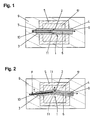
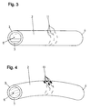
- the valve arrangement according to the invention is highly schematic 1 shown.
- the centerpiece is a short piece of hose 2 made of silicone material, which is fluid-tight in front of its two open ends 3, 4 a housing part 5 is mounted.
- the housing part 5 belongs to a first one Fluid space 5 'in which a fluid, for. B. is a liquid.
- the hose piece 2 is between the bearing points at the two open ends its wall outside is surrounded by the liquid in the first fluid space 5 '.
- the lumen 6 of the tube piece 2 opens with its two openings 7, 8 in a second fluid space, which in FIGS. 1 and 2 as a whole 9 and is indicated by a hatched area.
- In the Lumen 6 of the tube piece 2 is through an opening 7 through Pipe piece 10 inserted as an actuating part, which is just before the area the slots 11 in the tube piece 2 ends.
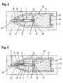
- FIG 3 and 4 An example of the shape and configuration of the slots 11 is shown in FIG 3 and 4 shown. There are three rows around the periphery Slits 11 are provided approximately in the center of the length of the tube piece 2. The slots 11 are microfine cuts that run through the hose wall.
- Fig. 1 the valve assembly 1 is shown in the closed state. Due to the inherent restoring force inherent in the hose section 2 the slots 11 of its silicone elastomer material are closed, so that one with a slight overpressure in the housing part 5 (first Fluid space 5 ') liquid not present through the slots 11 in the Lumen 6 of the hose section 2 can enter.
- 5 and 6 is a practical example of the application of the in 1 to 4 shown valve assembly. These are around a marker pen M shown schematically in section, the one Usual cylindrical or flattened tubular device housing 12 with has tapered housing tip 13. The device housing 12 encloses a reservoir 14 for the writing fluid of the marker pen
- an opening 15 is provided in which the one End 7 of the tube piece 2 with its outside fluid-tight is stored. That arranged coaxially to the longitudinal axis of the device housing 12 Hose section 2 is also with its other end 4 in one Holding element 16 fixed in the device housing 12, the through openings 17 for the writing fluid.
- the opening 8 located at the end 4 of the tube piece 2 is by a plug 18 in the form of a silicone cord piece tightly closed.
- the writing tip 19 of the marker pen M inserted with its shaft 20.
- the writing tip 19 itself forms the actuating part for the valve arrangement 1, its stem 20 again until just before the slots 11 in the hose section 2.
- the Writing tip 19 with shaft 20 is also made of fiber material, such as this with marker pens M for transporting the writing fluid Capillary action is common.
- the opening 21 of the device housing facing away from the housing tip 13 is otherwise closed by a cap 22 in which a pressure compensation element 23 used in the form of a hydrophobic, semipermeable membrane is.
- the latter is ultrasonically welded to the cap 22.
- the tube piece 2 is in turn from the shaft 20 of the nib 19 deflected and deformed. This will open them up Slits 11 in the hose section 2 so that the in the reservoir 14 (first Fluid space) liquid present in the lumen 6 of the tube piece 2 can occur and the capillary forces in the nib 19 to the paper sheet 24 is transported.
- the latter forms according to the above Terminology practically the second fluid space.
Landscapes
- Health & Medical Sciences (AREA)
- Life Sciences & Earth Sciences (AREA)
- Engineering & Computer Science (AREA)
- Heart & Thoracic Surgery (AREA)
- Animal Behavior & Ethology (AREA)
- Pulmonology (AREA)
- Anesthesiology (AREA)
- Biomedical Technology (AREA)
- Mechanical Engineering (AREA)
- Hematology (AREA)
- Biophysics (AREA)
- General Health & Medical Sciences (AREA)
- Public Health (AREA)
- Veterinary Medicine (AREA)
- Pens And Brushes (AREA)
- Lift Valve (AREA)
- Check Valves (AREA)
Applications Claiming Priority (3)
| Application Number | Priority Date | Filing Date | Title |
|---|---|---|---|
| DE19626755 | 1996-07-03 | ||
| DE19626755A DE19626755A1 (de) | 1996-07-03 | 1996-07-03 | Ventilanordnung zur Steuerung eines Fluiddurchflusses zwischen zwei Fluidräumen und damit versehenes Schreibgerät |
| PCT/EP1997/002935 WO1998001307A1 (de) | 1996-07-03 | 1997-06-06 | Ventilanordnung zur steuerung eines fluiddurchflusses zwischen zwei fluidräumen und damit versehenes schreibgerät |
Publications (2)
| Publication Number | Publication Date |
|---|---|
| EP0910510A1 EP0910510A1 (de) | 1999-04-28 |
| EP0910510B1 true EP0910510B1 (de) | 2000-08-23 |
Family
ID=7798798
Family Applications (1)
| Application Number | Title | Priority Date | Filing Date |
|---|---|---|---|
| EP97925985A Expired - Lifetime EP0910510B1 (de) | 1996-07-03 | 1997-06-06 | Ventilanordnung zur steuerung eines fluiddurchflusses zwischen zwei fluidräumen und damit versehenes schreibgerät |
Country Status (8)
| Country | Link |
|---|---|
| EP (1) | EP0910510B1 (pt) |
| JP (1) | JP2001501878A (pt) |
| AU (1) | AU3094097A (pt) |
| BR (1) | BR9710102A (pt) |
| CA (1) | CA2259397A1 (pt) |
| DE (2) | DE19626755A1 (pt) |
| TR (1) | TR199802780T2 (pt) |
| WO (1) | WO1998001307A1 (pt) |
Families Citing this family (7)
| Publication number | Priority date | Publication date | Assignee | Title |
|---|---|---|---|---|
| DE19810217A1 (de) * | 1998-03-10 | 1999-09-16 | Oliver Weis | Flüssigkeitsspender, insbesondere Flüssigarzneispender, Kosmetikapplikator, Tintenschreibgerät oder dergleichen |
| EP1171316B1 (de) * | 1999-04-17 | 2002-10-16 | Faber- Castell AG | Auftragsgerät |
| DE29912647U1 (de) * | 1999-07-26 | 1999-09-23 | Weiß, Oliver, 90530 Wendelstein | Spender für Toiletten-Hygiene-Flüssigkeiten |
| DE19934445A1 (de) * | 1999-07-26 | 2001-02-01 | Oliver Weis | Ventilanordnung zur Steuerung eines Fluiddurchflusses |
| DE10041323A1 (de) * | 2000-08-23 | 2002-03-07 | Oliver Weis | Stiftartiger Applikator zum Auftragen von Flüssigkeiten, insbesondere Tinten-Schreibgerät oder Kosmetikapplikator |
| DE10103437B4 (de) * | 2001-01-25 | 2006-07-06 | Schmidt Feintechnik Gmbh | Schreib- und/oder Dosiergerät für Tinte |
| JP2025118526A (ja) * | 2024-01-31 | 2025-08-13 | 株式会社東山 | ペン |
Family Cites Families (11)
| Publication number | Priority date | Publication date | Assignee | Title |
|---|---|---|---|---|
| DE264882C (pt) * | ||||
| DE926054C (de) * | 1950-07-13 | 1955-04-04 | Ehrenreich Haeuselmann | Fuellschreibgeraet mit in der Spitzenbohrung des Halters des Geraetes axial verschiebbar gelagertem Schreibroehrchen und gesteuertem Schreibgutfluss |
| US2642041A (en) * | 1951-01-18 | 1953-06-16 | Miessner Inventions Inc | Antileak fountain pen |
| FR1360234A (fr) * | 1963-03-18 | 1964-05-08 | Ydev Sa | Récipient distributeur-étaleur pour colle et autres liquides visqueux |
| US4549879A (en) * | 1983-05-03 | 1985-10-29 | Catheter Technology Corporation | Valved two-way catheter |
| US4737152A (en) * | 1986-07-02 | 1988-04-12 | Becton, Dickinson And Company | Catheter assembly |
| DE4100644A1 (de) * | 1990-01-20 | 1991-08-29 | Schmidt Feinmech | Schreib- oder dosiergeraet |
| US5250034A (en) * | 1990-09-17 | 1993-10-05 | E-Z-Em, Inc. | Pressure responsive valve catheter |
| DE4106839C2 (de) * | 1991-03-04 | 1994-06-30 | Suspa Spannbeton Gmbh | Ventil, insbesondere zur Nachinjektion eines Verpreßankers im Baugrund |
| JP2679918B2 (ja) * | 1992-02-17 | 1997-11-19 | 二郎 堀 | 筆記具 |
| ZA948098B (en) * | 1993-10-18 | 1995-06-05 | Gillette Co | Liquid ink |
-
1996
- 1996-07-03 DE DE19626755A patent/DE19626755A1/de not_active Withdrawn
-
1997
- 1997-06-06 TR TR1998/02780T patent/TR199802780T2/xx unknown
- 1997-06-06 BR BR9710102-8A patent/BR9710102A/pt not_active Application Discontinuation
- 1997-06-06 JP JP10504695A patent/JP2001501878A/ja active Pending
- 1997-06-06 DE DE59702246T patent/DE59702246D1/de not_active Expired - Fee Related
- 1997-06-06 AU AU30940/97A patent/AU3094097A/en not_active Abandoned
- 1997-06-06 EP EP97925985A patent/EP0910510B1/de not_active Expired - Lifetime
- 1997-06-06 WO PCT/EP1997/002935 patent/WO1998001307A1/de not_active Ceased
- 1997-06-06 CA CA002259397A patent/CA2259397A1/en not_active Abandoned
Also Published As
| Publication number | Publication date |
|---|---|
| AU3094097A (en) | 1998-02-02 |
| WO1998001307A1 (de) | 1998-01-15 |
| JP2001501878A (ja) | 2001-02-13 |
| TR199802780T2 (xx) | 1999-03-22 |
| CA2259397A1 (en) | 1998-01-15 |
| DE59702246D1 (de) | 2000-09-28 |
| BR9710102A (pt) | 2000-01-11 |
| DE19626755A1 (de) | 1998-01-08 |
| EP0910510A1 (de) | 1999-04-28 |
Similar Documents
| Publication | Publication Date | Title |
|---|---|---|
| EP1170061B1 (de) | Austragvorrichtung für Medien | |
| DE4037641C2 (de) | Katheter | |
| EP0495033B1 (de) | Dialysesonde | |
| DE19654723A1 (de) | Dosierventil für einen flexiblen Flüssigkeitsbehälter | |
| CH623643A5 (pt) | ||
| DE2133101A1 (de) | Behaelter mit einem Durchflussventil und Durchflussventil | |
| DD293175A5 (de) | Absperrventil, insbesondere ein entleerungsventil fuer sammelbeutel, wie beispielsweise urinsammelbeutel | |
| EP0910510B1 (de) | Ventilanordnung zur steuerung eines fluiddurchflusses zwischen zwei fluidräumen und damit versehenes schreibgerät | |
| EP0765769B1 (de) | Schreibgerät, insbesondere Füllhalter | |
| DE2153876B2 (de) | Druckübertrager zwischen zwei Medien | |
| DE2514929A1 (de) | Schlauchventil | |
| DE102008035310A1 (de) | Medizinisches Instrument mit einem flexiblen Dichtungssystem | |
| EP0912413B1 (de) | Kunststoffhahn für flüssigkeitsbehälter | |
| DE102013106550A1 (de) | Luer-Lock-Verbinder mit Nuten | |
| DE2622096B2 (de) | Ventil für ein Gasfeuerzeug | |
| DE2905839A1 (de) | Schreibgeraet | |
| EP0160807A2 (de) | Spülvorrichtung für einen Katheter | |
| EP0159041B1 (de) | Ablassventil für Blutdruckmessgeräte und dergleichen | |
| EP1637178B1 (de) | Ventil für medizinische Instrumente | |
| DE19934445A1 (de) | Ventilanordnung zur Steuerung eines Fluiddurchflusses | |
| DE857772C (de) | Instrument mit Kugelspitze, insbesondere Kugelschreiber | |
| DE3612792C2 (pt) | ||
| DE3009100C2 (de) | Schreibgerät | |
| DE9207414U1 (de) | Chirurgisches Instrument | |
| EP0545963B1 (de) | Nachfüllbehältnis zum nachfüllen eines schreib-, mal- oder zeichengerätes |
Legal Events
| Date | Code | Title | Description |
|---|---|---|---|
| PUAI | Public reference made under article 153(3) epc to a published international application that has entered the european phase |
Free format text: ORIGINAL CODE: 0009012 |
|
| GRAG | Despatch of communication of intention to grant |
Free format text: ORIGINAL CODE: EPIDOS AGRA |
|
| 17P | Request for examination filed |
Effective date: 19990128 |
|
| AK | Designated contracting states |
Kind code of ref document: A1 Designated state(s): DE ES FR GB IT |
|
| 17Q | First examination report despatched |
Effective date: 19990423 |
|
| GRAG | Despatch of communication of intention to grant |
Free format text: ORIGINAL CODE: EPIDOS AGRA |
|
| GRAH | Despatch of communication of intention to grant a patent |
Free format text: ORIGINAL CODE: EPIDOS IGRA |
|
| GRAH | Despatch of communication of intention to grant a patent |
Free format text: ORIGINAL CODE: EPIDOS IGRA |
|
| GRAA | (expected) grant |
Free format text: ORIGINAL CODE: 0009210 |
|
| AK | Designated contracting states |
Kind code of ref document: B1 Designated state(s): DE ES FR GB IT |
|
| PG25 | Lapsed in a contracting state [announced via postgrant information from national office to epo] |
Ref country code: ES Free format text: THE PATENT HAS BEEN ANNULLED BY A DECISION OF A NATIONAL AUTHORITY Effective date: 20000823 |
|
| GBT | Gb: translation of ep patent filed (gb section 77(6)(a)/1977) |
Effective date: 20000906 |
|
| REF | Corresponds to: |
Ref document number: 59702246 Country of ref document: DE Date of ref document: 20000928 |
|
| ET | Fr: translation filed | ||
| ITF | It: translation for a ep patent filed | ||
| PGFP | Annual fee paid to national office [announced via postgrant information from national office to epo] |
Ref country code: GB Payment date: 20010518 Year of fee payment: 5 |
|
| PGFP | Annual fee paid to national office [announced via postgrant information from national office to epo] |
Ref country code: FR Payment date: 20010618 Year of fee payment: 5 |
|
| PLBE | No opposition filed within time limit |
Free format text: ORIGINAL CODE: 0009261 |
|
| STAA | Information on the status of an ep patent application or granted ep patent |
Free format text: STATUS: NO OPPOSITION FILED WITHIN TIME LIMIT |
|
| 26N | No opposition filed | ||
| PGFP | Annual fee paid to national office [announced via postgrant information from national office to epo] |
Ref country code: DE Payment date: 20010822 Year of fee payment: 5 |
|
| REG | Reference to a national code |
Ref country code: GB Ref legal event code: IF02 |
|
| PG25 | Lapsed in a contracting state [announced via postgrant information from national office to epo] |
Ref country code: GB Free format text: LAPSE BECAUSE OF NON-PAYMENT OF DUE FEES Effective date: 20020606 |
|
| PG25 | Lapsed in a contracting state [announced via postgrant information from national office to epo] |
Ref country code: DE Free format text: LAPSE BECAUSE OF NON-PAYMENT OF DUE FEES Effective date: 20030101 |
|
| GBPC | Gb: european patent ceased through non-payment of renewal fee |
Effective date: 20020606 |
|
| PG25 | Lapsed in a contracting state [announced via postgrant information from national office to epo] |
Ref country code: FR Free format text: LAPSE BECAUSE OF NON-PAYMENT OF DUE FEES Effective date: 20030228 |
|
| REG | Reference to a national code |
Ref country code: FR Ref legal event code: ST |
|
| PG25 | Lapsed in a contracting state [announced via postgrant information from national office to epo] |
Ref country code: IT Free format text: LAPSE BECAUSE OF NON-PAYMENT OF DUE FEES Effective date: 20050606 |