EP0910889B1 - Verfahren zum isolieren des stators eines elektronisch kommutierten gleichstrommotors - Google Patents
Verfahren zum isolieren des stators eines elektronisch kommutierten gleichstrommotors Download PDFInfo
- Publication number
- EP0910889B1 EP0910889B1 EP97946756A EP97946756A EP0910889B1 EP 0910889 B1 EP0910889 B1 EP 0910889B1 EP 97946756 A EP97946756 A EP 97946756A EP 97946756 A EP97946756 A EP 97946756A EP 0910889 B1 EP0910889 B1 EP 0910889B1
- Authority
- EP
- European Patent Office
- Prior art keywords
- internal stator
- stator
- mould
- air gap
- magnetic air
- Prior art date
- Legal status (The legal status is an assumption and is not a legal conclusion. Google has not performed a legal analysis and makes no representation as to the accuracy of the status listed.)
- Expired - Lifetime
Links
- 238000000034 method Methods 0.000 title claims description 16
- 239000004831 Hot glue Substances 0.000 claims description 8
- 238000002347 injection Methods 0.000 claims description 8
- 239000007924 injection Substances 0.000 claims description 8
- 229920001169 thermoplastic Polymers 0.000 claims description 7
- 239000004416 thermosoftening plastic Substances 0.000 claims description 7
- 238000004804 winding Methods 0.000 claims description 5
- 239000004033 plastic Substances 0.000 description 11
- 229920003023 plastic Polymers 0.000 description 11
- 238000009413 insulation Methods 0.000 description 5
- 229920000728 polyester Polymers 0.000 description 4
- 239000010410 layer Substances 0.000 description 3
- 229920002647 polyamide Polymers 0.000 description 3
- 239000004952 Polyamide Substances 0.000 description 2
- 239000004698 Polyethylene Substances 0.000 description 2
- 229920006018 co-polyamide Polymers 0.000 description 2
- 238000005538 encapsulation Methods 0.000 description 2
- 238000001746 injection moulding Methods 0.000 description 2
- 239000000463 material Substances 0.000 description 2
- 229920000573 polyethylene Polymers 0.000 description 2
- -1 polyethylenes Polymers 0.000 description 2
- 239000011248 coating agent Substances 0.000 description 1
- 238000000576 coating method Methods 0.000 description 1
- 238000001816 cooling Methods 0.000 description 1
- 238000011161 development Methods 0.000 description 1
- 230000018109 developmental process Effects 0.000 description 1
- HDERJYVLTPVNRI-UHFFFAOYSA-N ethene;ethenyl acetate Chemical class C=C.CC(=O)OC=C HDERJYVLTPVNRI-UHFFFAOYSA-N 0.000 description 1
- 229920006226 ethylene-acrylic acid Polymers 0.000 description 1
- 238000007765 extrusion coating Methods 0.000 description 1
- 238000003780 insertion Methods 0.000 description 1
- 230000037431 insertion Effects 0.000 description 1
- 238000003475 lamination Methods 0.000 description 1
- 238000004519 manufacturing process Methods 0.000 description 1
- 238000000465 moulding Methods 0.000 description 1
- 229920001200 poly(ethylene-vinyl acetate) Polymers 0.000 description 1
- 239000000843 powder Substances 0.000 description 1
- 230000001681 protective effect Effects 0.000 description 1
- 239000011241 protective layer Substances 0.000 description 1
- 239000007921 spray Substances 0.000 description 1
- 239000000126 substance Substances 0.000 description 1
- 229920003002 synthetic resin Polymers 0.000 description 1
- 239000000057 synthetic resin Substances 0.000 description 1
- 229920001897 terpolymer Polymers 0.000 description 1
- 229920002554 vinyl polymer Polymers 0.000 description 1
Images


Classifications
-
- H—ELECTRICITY
- H02—GENERATION; CONVERSION OR DISTRIBUTION OF ELECTRIC POWER
- H02K—DYNAMO-ELECTRIC MACHINES
- H02K15/00—Processes or apparatus specially adapted for manufacturing, assembling, maintaining or repairing of dynamo-electric machines
- H02K15/12—Impregnating, moulding insulation, heating or drying of windings, stators, rotors or machines
-
- F—MECHANICAL ENGINEERING; LIGHTING; HEATING; WEAPONS; BLASTING
- F04—POSITIVE - DISPLACEMENT MACHINES FOR LIQUIDS; PUMPS FOR LIQUIDS OR ELASTIC FLUIDS
- F04D—NON-POSITIVE-DISPLACEMENT PUMPS
- F04D25/00—Pumping installations or systems
- F04D25/02—Units comprising pumps and their driving means
- F04D25/06—Units comprising pumps and their driving means the pump being electrically driven
- F04D25/0606—Units comprising pumps and their driving means the pump being electrically driven the electric motor being specially adapted for integration in the pump
- F04D25/0613—Units comprising pumps and their driving means the pump being electrically driven the electric motor being specially adapted for integration in the pump the electric motor being of the inside-out type, i.e. the rotor is arranged radially outside a central stator
- F04D25/0646—Details of the stator
-
- F—MECHANICAL ENGINEERING; LIGHTING; HEATING; WEAPONS; BLASTING
- F05—INDEXING SCHEMES RELATING TO ENGINES OR PUMPS IN VARIOUS SUBCLASSES OF CLASSES F01-F04
- F05D—INDEXING SCHEME FOR ASPECTS RELATING TO NON-POSITIVE-DISPLACEMENT MACHINES OR ENGINES, GAS-TURBINES OR JET-PROPULSION PLANTS
- F05D2300/00—Materials; Properties thereof
- F05D2300/40—Organic materials
- F05D2300/43—Synthetic polymers, e.g. plastics; Rubber
-
- H—ELECTRICITY
- H02—GENERATION; CONVERSION OR DISTRIBUTION OF ELECTRIC POWER
- H02K—DYNAMO-ELECTRIC MACHINES
- H02K3/00—Details of windings
- H02K3/44—Protection against moisture or chemical attack; Windings specially adapted for operation in liquid or gas
-
- H—ELECTRICITY
- H02—GENERATION; CONVERSION OR DISTRIBUTION OF ELECTRIC POWER
- H02K—DYNAMO-ELECTRIC MACHINES
- H02K5/00—Casings; Enclosures; Supports
- H02K5/04—Casings or enclosures characterised by the shape, form or construction thereof
- H02K5/12—Casings or enclosures characterised by the shape, form or construction thereof specially adapted for operating in liquid or gas
-
- Y—GENERAL TAGGING OF NEW TECHNOLOGICAL DEVELOPMENTS; GENERAL TAGGING OF CROSS-SECTIONAL TECHNOLOGIES SPANNING OVER SEVERAL SECTIONS OF THE IPC; TECHNICAL SUBJECTS COVERED BY FORMER USPC CROSS-REFERENCE ART COLLECTIONS [XRACs] AND DIGESTS
- Y10—TECHNICAL SUBJECTS COVERED BY FORMER USPC
- Y10T—TECHNICAL SUBJECTS COVERED BY FORMER US CLASSIFICATION
- Y10T29/00—Metal working
- Y10T29/49—Method of mechanical manufacture
- Y10T29/49002—Electrical device making
- Y10T29/49009—Dynamoelectric machine
Definitions
- the invention relates to a method for insulating the inner stator of an electronically commutated DC motor, a device for carrying out such a method, and an inner stator, which can be produced by this method.
- the DE 31 23 814 A1 shows a stator core of an electronically commutated external rotor motor, which is completely insulated by molding the provided with main and minor poles stator core with a thermoplastic in a spray operation.
- the WO 96/31936 A1 describes an apparatus for ejecting the interstage stator assembly of an internal rotor motor formed by assembling a stack of stator laminations and stator windings wherein molten plastic is injected under pressure into the interior of the assembly.
- This device comprises two axially displaceable jaws, which are arranged at axial ends of the intermediate stator assembly such that the assembly remains free in its radial extent.
- a shaft is disposed in the mold to produce a concentric bore for receiving a rotor assembly upon injection of the plastic into the interior of the intermediate stator assembly, the latter subsequently being installed in that bore.
- the molten plastic When the molten plastic is injected, it is pressed into internal cavities between the poles of the intermediate stator assembly and fills them.
- the molten plastic also forms a rear end cap for the stator assembly.
- the object of the invention is to provide a method for insulating stators, which also meets extreme insulation and protection conditions for electric motors.
- Fig. 1 is an average of an injection mold 20 for producing a stator 1 according to an embodiment of the invention shown schematically.
- the injection mold consists for example of three laterally extendable jaws 21, which are arranged around the laminated core 2 of the stator 1 around. Between two of the jaws 21, a supply line 22 for injecting the plastic is arranged.
- the centering of the stator 1 is on the one hand by means of a centering mandrel 23, which projects conically or precisely into the bearing seat 3 of the bearing support tube 4, made and on the other hand axially fixed with a plunger 24. This prevents the plastic from getting into the interior of the bearing support tube 4 during the injection process.
- the injection of the thermoplastic hot melt adhesive used here takes place at about 200 ° C.
- the jaws 21 are applied to the flange 5 with axial pressure and thus causes a seal.
- An additional seal is obtained by the plunger 24, which defines a cavity together with the closed jaws 21. This ensures that outside of this flange 5 no hot melt adhesive is injected.
- a receiving part 25 of the injection molding tool 20 contains in a recess the centering mandrel 23, conical surfaces 26,27, which provide for the guidance of the jaws 21, and a bottom 28th Not shown slots allow the insertion of ribs 7 of a fan housing 6 in the receiving part 25.
- the fan housing 6 shown here as an example consists of bearing support tube 4 and flange 5 and is made in one piece as a plastic part.
- the magnetic air gap 8 between rotor and stator is shown by means of double arrows.
- the magnetic air gap 8 facing side of the stator 1 is enclosed at a distance from the mold, which is smaller than the existing air gap of this engine
- the mold is opened and the overmolded stator 1 is removed.
- the demolding is much easier.
- thermoplastic hot melt adhesive polyamide-based used with the name MACROMELT 6790 Henkel.
- the stator 1 consists essentially of a laminated core 2, a winding 10 and a printed circuit board 11 and is attached to the outer periphery of the bearing support tube 4. On the circuit board 11 are position-sensitive electronic components that would be displaced by an excessive injection pressure and would make the engine unusable. In addition, the plastic for the sheathing of the circuit board (11) must be so flexible that z. B. SMD components are not blasted off.
- Fig. 2 the three jaws 21 of the tool 20 are shown in section in the closed position, wherein the inner recess 31 of the jaws 21 limits the outer diameter of the sheath of the stator 1.
- the shaft of the plunger 24 is surrounded by a protective sleeve 32 and this of a guide sleeve 33.
- the guide sleeve 33 forms the radial stop for the jaws 21st
- a fan housing 6 with a flange 5, ribs 7 and a bearing support tube 4 is shown.
- a stator 1 of an electronically commutated DC motor is also arranged on the outer circumference of the bearing support tube 4 as described above.
- the Fig. 5 shows the stator 1 according to the invention.
- the contours of the essential parts of the injection molding tool 20 were drawn with dash-dot lines. For clarity, an enlarged view of the stator was chosen. Therein, the various areas of the extrusion coating 9 can be seen, such. B. the very thin layer around the laminated core 2 around. Only by the process steps of this invention and the choice of materials this encapsulation was possible.
- Fig. 6 the section through a fully assembled fan with a stator 1 according to an embodiment of the invention is shown.
- the stator 1 and its parts have already been described above.
- the rotor of this motor consists essentially of rotor magnet 40, rotor bell 41 and fan hub 42 with fan blades 43 (dashed lines).
- the invention has succeeded in spite of the envelope 9 and the laminated core 2, in a series product, without changing this, nor to obtain an air gap 8, the Operation of the motor without mechanical reworking on the circumference of the stator 1 allows.
Landscapes
- Engineering & Computer Science (AREA)
- Mechanical Engineering (AREA)
- General Engineering & Computer Science (AREA)
- Manufacturing & Machinery (AREA)
- Power Engineering (AREA)
- Manufacture Of Motors, Generators (AREA)
- Insulation, Fastening Of Motor, Generator Windings (AREA)
Description
- Die Erfindung betrifft ein Verfahren zum Isolieren des Innenstators eines elektronisch kommutierten Gleichstrommotors, eine Vorrichtung zur Durchführung eines solchen Verfahrens, und einen Innenstator, der nach diesem Verfahren herstellbar ist.
- Bei Elektromotoren, die in sog. Reinräumen, in feuchter oder aggressiver Umgebung eingesetzt werden, ist es erforderlich, die empfindlichen Teile des Motors, z. B. Wicklung und Leiterplatte, mit einer Schutzschicht zu versehen. So ist es z. B. aus der
DE 37 37 050 A1 bekannt, den Stator eines Elektromotors mit Kunstharz zu umgießen. Die Aufgabe besteht bei dieser Veröffentlichung im Wesentlichen darin, die Herstellung der Verbindung zwischen der Statorwicklung und der Leiterplatte einfacher zu gestalten. - Die
DE 31 23 814 A1 zeigt ein Ständerblechpaket eines elektronisch kommutierten Außenläufermotors, welches durch Umspritzen des mit Haupt- und Nebenpolen versehenen Ständerblechpakets mit einem Thermoplast in einem Spritzarbeitsgang komplett isoliert ist. - Die
WO 96/31936 A1 - Ferner ist es bekannt, eine Pulverbeschichtung vorzunehmen. Die bekannten Verfahren erfordern nicht nur mechanische Nacharbeit, sondern sind auch nicht in der Lage, die Bedingungen höherer isolationsklassen, z. B. Schutzart DIN/VDE 0470 IP 54 zu erfüllen.
- Aufgabe der Erfindung ist es, ein Verfahren zum Isolieren von Statoren bereit zu stellen, das auch extreme Isolations- und Schutzbedingungen für Elektromotoren erfüllt.
- Diese Aufgabe wird gelöst durch die Merkmale des Anspruchs 1. Weitere Einzelheiten und vorteilhafte Weiterbildungen der Erfindung ergeben sich aus den im folgenden beschriebenen und in der Zeichnung dargestellten Ausführungsbeispielen.
-
-
Fig. 1 : einen Schnitt durch ein Spritzwerkzeug (schematisch); -
Fig. 2 : einen Schnitt entlang der Linie II-II derFig. 1 ; -
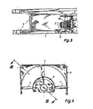
Fig. 3 : einen Schnitt durch einen Stator ohne Isolationsumhüllung eines Lüfters entlang der Linie III-III inFig. 4 ; -
Fig. 4 : eine Unteransicht eines Stators gemäßFig. 3 ; -
Fig. 5 : einen Schnitt durch einen Stator nach einem Ausführungsbeispiel der Erfindung mit Isolationsumhüllung ; -
Fig. 6 : einen Schnitt durch einen in einem Lüfter montierten Stator mit Umhüllung ; - In
Fig. 1 ist im Schnitt ein Spritzwerkzeug 20 zur Herstellung eines Stators 1 gemäß einem Ausführungsbeispiel der Erfindung schematisch dargestellt. Hier besteht die Spritzform beispielsweise aus drei seitlich ausfahrbaren Backen 21 , die um das Blechpaket 2 des Stators 1 herum angeordnet sind. Zwischen zwei der Backen 21 ist eine Zuführungsleitung 22 zum Einspritzen des Kunststoffs angeordnet. Die Zentrierung des Stators 1 wird einerseits mittels eines Zentrierdorns 23 , der konisch oder passgenau in den Lagersitz 3 des Lagertragrohrs 4 hineinragt, vorgenommen und andererseits mit einem Stößel 24 axial fixiert. Dadurch wird verhindert, daß beim Spritzvorgang Kunststoff in das Innere des Lagertragrohrs 4 gelangt . Die Einspritzung des hier verwendeten thermoplastischen Schmelzklebers erfolgt bei etwa 200°C.
Die Backen 21 liegen mit axialem Druck am Flansch 5 an und bewirkt so eine Abdichtung. Eine zusätzliche Abdichtung erhält man durch den Stößel 24 , der zusammen mit den geschlossenen Backen 21 einen Hohlraum definiert. So wird erreicht, daß außerhalb dieses Flanschs 5 kein Schmelzkleber injiziert wird. - Ein Aufnahmeteil 25 des Spritzwerkzeugs 20 enthält in einer Ausnehmung den Zentrierdorn 23 , konische Flächen 26,27 , die für die Führung der Backen 21 sorgen , und einen Boden 28 . Nicht dargestellte Schlitze erlauben das Einführen von Rippen 7 eines Lüftergehäuses 6 in das Aufnahmeteil 25. Das hier als Beispiel gezeigte Lüftergehäuse 6 besteht aus Lagertragrohr 4 und Flansch 5 und ist einstückig als Kunststoffteil ausgeführt.
- Nach Einlegen des Stators 1 , der am Boden 28 der Ausnehmung des Aufnahmeteils 25 aufliegt , werden die Backen 21 und der Stößel 24 bis an einen Anschlag bewegt und bilden eine Form , die den Stator mit geringem Abstand umschließt. Anschließend wird der Kunststoff unter Druck über die Zuführungsleitung 22 in die oben beschriebene
- Form eingespritzt und so entsteht eine Umhüllung bzw. Isolationsschicht 9 (schraffiert dargestellt). Der magnetische Luftspalt 8 zwischen Rotor und Stator ist mittels Doppelpfeilen dargestellt Dabei wird zum Isolieren des Stators 1 des Außenläufermotors die dem magnetischen Luftspalt 8 zugewandte Seite des Stators 1 mit einem Abstand von der Form umschlossen, der kleiner ist als der im Betrieb vorhandene Luftspalt dieses Motors Nach einer kurzen Pause, die durch zusätzliches Kühlen der Form noch verkürzt werden kann, wird die Form geöffnet und der umspritzte Stator 1 wird entnommen. Durch mindestens drei seitlich (im wesentlichen in radialer Richtung) ausfahrbare Backen 21 wird die Entformung wesentlich erleichtert.
- Als Schmelzkleber für die Umhüllung 9 kommen vor allem folgende Stoffe in Frage :
- Polyamide; Co-Polyamide; Co-Polyester, Hoch- oder Niederdruck-Polyethylene;
- Ethylenvinylacetate; Polyester; Ethylen-Acrylsäure-Acrylsäureester (EAA) ;
- Terpolyamide; Ethylen-Vinylacetat-Acrylsäure-Terpolymere.
- Je nach Anforderungen, die für den Verwendungsfall bestehen, wird der geeignete Kunststoff ermittelt. So wurde für das in
Fig. 3 bis 6 dargestellte Ausführungsbeispiel (für die Isolationsschicht 9 des Stators 1 eines elektronisch kommutierten Gleichstrommotors in einem Lüfter) ein thermoplastischer Schmelzklebstoff auf Polyamid-Basis verwendet mit der Bezeichnung MACROMELT 6790 der Firma Henkel. - Dieser Kunststoff kann mit relativ geringem Druck eingespritzt werden und haftet gut an den verschiedenen Werkstoffen, aus denen der Stator 1 besteht. Die Erfüllung dieser Bedingungen ist erforderlich, da es sich um einen elektronisch kommutierten Gleichstrommotor handelt. Dieser bekannte Motor wird nur soweit beschrieben wie es für das Verständnis dieser Erfindung erforderlich ist. Der Stator 1 besteht im wesentlichen aus einem Blechpaket 2, einer Wicklung 10 und einer Leiterplatte 11 und ist am Außenumfang des Lagertragrohrs 4 befestigt. Auf der Leiterplatte 11 befinden sich lageempfindliche elektronische Bauelemente, die durch einen zu hohen Einspritzdruck verschoben würden und so den Motor unbrauchbar machen würden. Außerdem muß der Kunststoff für die Ummantelung der Leiterplatte (11) so flexibel sein, daß z. B. SMD-Bauelemente nicht abgesprengt werden.
- In
Fig. 2 sind die drei Backen 21 des Werkzeugs 20 im Schnitt in geschlossener Stellung dargestellt, wobei die innere Ausnehmung 31 der Backen 21 den Außendurchmesser der Umhüllung des Stators 1 begrenzt. Der Schaft des Stößels 24 wird von einer Schutzhülse 32 und diese von einer Führungshülse 33 umgeben. Die Führungshülse 33 bildet den radialen Anschlag für die Backen 21. - In
Fig. 3 und 4 ist ein Lüftergehäuse 6 mit einem Flansch 5, Rippen 7 und einem Lagertragrohr 4 dargestellt. Ein Stator 1 eines elektronisch kommutierten Gleichstrommotors ist auch dem Außenumfang des Lagertragrohrs 4 wie oben beschrieben angeordnet. Diese Abbildungen, die den Zustand des Stators 1 vor dem Umspritzen deutlich zeigen, sollen zum besseren Verständnis dieser Erfindung beitragen. - Die
Fig. 5 zeigt den Stator 1 nach der Erfindung. Die Konturen der wesentlichen Teile des Spritzwerkzeuges 20 wurden mit Strichpunkt-Linien eingezeichnet. Zur Verdeutlichung wurde eine vergrößerte Darstellung des Stators gewählt. Darin sind die verschiedenen Bereiche der Umspritzung 9 erkennbar, wie z. B. die sehr dünne Schicht um das Blechpaket 2 herum. Erst durch die Verfahrensschritte dieser Erfindung und die Werkstoffauswahl wurde diese Umspritzung möglich. - In
Fig. 6 ist der Schnitt durch einen fertig montierten Lüfter mit einem Stator 1 gemäß einem Ausführungsbeispiel der Erfindung dargestellt. Der Stator 1 und seine Teile sind bereits oben beschrieben worden. Der Rotor dieses Motors besteht im wesentlichen aus Rotormagnet 40, Rotorglocke 41 und Lüfternabe 42 mit Lüfterflügeln 43 (Strichpunktlinien). Durch die Erfindung ist es gelungen, trotz der Umhüllung 9 auch um das Blechpaket 2, bei einem Serienprodukt, ohne dieses zu verändern, noch einen Luftspalt 8 zu erhalten, der den
Betrieb des Motors ohne mechanische Nacharbeit am Umfang des Stators 1 ermöglicht.
Claims (11)
- Verfahren zum Isolieren des eine Leiterplatte (11) tragende Innenstators (1) eines elektronisch kommutierten Außenläufer-Gleichstrommotors, welcher Innenstator (1) dazu ausgebildet ist, mit einem Außenrotor (40, 41, 42) zusammenzuwirken, der relativ zum Innenstator (1) um eine Drehachse drehbar und vom Innenstator durch einen magnetischen Luftspalt (8) getrennt ist, welches Verfahren folgende Schritte aufweist:a) Der Innenstator (1) wird in eine verschließbare Form (20) mit seitlich im wesentlichen in radialer Richtung ausfahrbaren Backen (21) eingebracht;b) die Form (20) wird geschlossen, wobei sie die Außenkonturen des Innenstators (1) einschließlich der Leiterplatte (11) mindestens bereichsweise im Bereich der dem magnetischen Luftspalt (8) zugewandten Seite des Innenstators (1) mit Abstand umschließt;c) in die Form (20) wird ein thermoplastischer Schmelzkleber (9) unter Druck eingespritzt;d) die Form (20) wird geöffnet, und der umspritzte Innenstator (1) wird entnommen.
- Verfahren nach Anspruch 1, bei welchem zwischen den Schritten c) und d) eine Pause eingeschaltet wird, um das Erstarren des thermoplastischen Schmelzklebers (9) in der Form (20) zu ermöglichen.
- Verfahren nach Anspruch 1 oder 2, bei welchem die verschließbare Form (20) gekühlt wird.
- Verfahren nach einem oder mehreren der vorhergehenden Ansprüche, bei welchem die dem magnetischen Luftspalt (8) zugewandte Seite des Innenstators (1) mit einem Abstand von der Form (20) umschlossen wird, welche kleiner ist als der im Betrieb vorhandene magnetische Luftspalt (8) des Motors.
- Verfahren nach einem oder mehreren der Ansprüche 1 bis 4, bei welchem der Innenstator (1) auf einem Trägerglied (5) angeordnet ist, insbesondere auf dem Flansch eines Lüftergehäuses (6), und durch Teile (21) der verschließbaren Form (20) im Zusammenwirken mit diesem Trägerglied (5) ein Hohlraum (12) gebildet wird, in welchen der thermoplastische Schmelzkleber injiziert wird.
- Verfahren nach Anspruch 5, bei welchem das Trägerglied (5) ungefähr senkrecht zur genannten Drehachse verläuft, und Teile der verschließbaren Form (20) zur Bildung des Hohlraums (12) im Wesentlichen senkrecht gegen dieses Trägerglied (5) angepresst werden.
- Vorrichtung zur Durchführung des Verfahrens nach einem oder mehreren der vorhergehenden Ansprüche, mit einer verschließbaren Form (20), welche bewegliche Backen (21) aufweist, die seitlich im wesentlichen in radialer Richtung verschiebbar und dazu ausgebildet sind, die Außenkonturen des Innenstators (1) eines elektronisch kommutierten Außenläufermotors einschließlich einer zugeordneten Leiterplatte (11) mindestens bereichsweise im Bereich der dem magnetischen Luftspalt (8) zugewandten Seite des Innenstators (1) mit Abstand zu umschließen.
- Vorrichtung nach Anspruch 7, welche zum Eingriff in und zum Verschließen eines am Stator (1) vorgesehenen Lagertragrohrs (4) eine Aufnahme mit einem Zentrierdorn (23) und einem Stößel (24), aufweist, um eine Beschichtung der Innenseite dieses Lagertragrohrs (4) zu verhindern.
- Innenstator (1) für einen elektronisch kommutierten Außenläufer-Gleichstrommotor, welcher Innenstator auf seiner dem magnetischen Luftspalt (8) zugewandten Seite eine durch Einspritzung von thermoplastischem Schmelzkleber zwischen dieser Seite und einer ihr gegenüber liegenden Spritzform entstandene Isolationsschicht (9) aufweist, deren Dicke kleiner ist als die Dicke des im Betrieb vorhandenen magnetischen Luftspalts (8).
- Innenstator nach Anspruch 9, bei welchem sich die Isolationsschlicht (9) von der dem magnetischen Luftspalt (8) zugewandten Seite des Innenstators (1) über die Wicklung (10) bis zu einem am Innenstator vorgesehenen Lagertragrohr (4) erstreckt.
- Innenstator nach einem oder mehreren der Ansprüche 9 bis 10, bei welchem sich die Isolationsschicht (9) nicht in das Innere des Lagertragrohrs (4) erstreckt.
Applications Claiming Priority (3)
| Application Number | Priority Date | Filing Date | Title |
|---|---|---|---|
| DE19644341 | 1996-10-28 | ||
| DE19644341 | 1996-10-28 | ||
| PCT/EP1997/005852 WO1998019382A1 (de) | 1996-10-28 | 1997-10-23 | Verfahren zum isolieren des stators eines elektronisch kommutierten gleichstrommotors |
Publications (2)
| Publication Number | Publication Date |
|---|---|
| EP0910889A1 EP0910889A1 (de) | 1999-04-28 |
| EP0910889B1 true EP0910889B1 (de) | 2009-08-19 |
Family
ID=7809940
Family Applications (1)
| Application Number | Title | Priority Date | Filing Date |
|---|---|---|---|
| EP97946756A Expired - Lifetime EP0910889B1 (de) | 1996-10-28 | 1997-10-23 | Verfahren zum isolieren des stators eines elektronisch kommutierten gleichstrommotors |
Country Status (4)
| Country | Link |
|---|---|
| US (1) | US5973424A (de) |
| EP (1) | EP0910889B1 (de) |
| DE (2) | DE19746605A1 (de) |
| WO (1) | WO1998019382A1 (de) |
Families Citing this family (34)
| Publication number | Priority date | Publication date | Assignee | Title |
|---|---|---|---|---|
| DE19836146A1 (de) * | 1998-08-10 | 2000-02-24 | Vacuumschmelze Gmbh | Verfahren zum Herstellen von induktiven Bauelementen |
| DE19841498C2 (de) * | 1998-09-10 | 2002-02-21 | Beru Ag | Verfahren zum Herstellen eines Elektronikbauelementes, insbesondere eines Hallsensors |
| US6753628B1 (en) | 1999-07-29 | 2004-06-22 | Encap Motor Corporation | High speed spindle motor for disc drive |
| US6300695B1 (en) | 1999-07-29 | 2001-10-09 | Encap Motor Corporation | High speed spindle motor with hydrodynamic bearings |
| US6437464B1 (en) | 1999-07-29 | 2002-08-20 | Encap Motor Corporation | Motor and disc assembly for computer hard drive |
| US6362554B1 (en) | 1999-07-29 | 2002-03-26 | Encap Motor Corporation | Stator assembly |
| US6617721B1 (en) | 1999-07-29 | 2003-09-09 | Encap Motor Corporation | High speed spindle motor |
| US6501616B1 (en) | 1999-07-29 | 2002-12-31 | Encap Motor Corporation | Hard disc drive with base incorporating a spindle motor stator |
| US6844636B2 (en) | 1999-12-17 | 2005-01-18 | Encap Motor Corporation | Spindle motor with encapsulated stator and method of making same |
| DE10024824A1 (de) * | 2000-05-19 | 2001-11-29 | Vacuumschmelze Gmbh | Induktives Bauelement und Verfahren zu seiner Herstellung |
| CZ20031901A3 (cs) | 2001-01-09 | 2003-11-12 | Black & Decker Inc. | Elektrický motor s kotvou potaženou tepelně vodivým plastem |
| US7814641B2 (en) | 2001-01-09 | 2010-10-19 | Black & Decker Inc. | Method of forming a power tool |
| US7096566B2 (en) * | 2001-01-09 | 2006-08-29 | Black & Decker Inc. | Method for making an encapsulated coil structure |
| US6946758B2 (en) | 2001-01-09 | 2005-09-20 | Black & Decker Inc. | Dynamoelectric machine having encapsulated coil structure with one or more of phase change additives, insert molded features and insulated pinion |
| US6892439B1 (en) | 2001-02-01 | 2005-05-17 | Encap Motor Corporation | Motor with stator made from linear core preform |
| US7036207B2 (en) | 2001-03-02 | 2006-05-02 | Encap Motor Corporation | Stator assembly made from a plurality of toroidal core segments and motor using same |
| ES2243890T3 (es) | 2002-03-02 | 2005-12-01 | EBM-PAPST ST. GEORGEN GMBH & CO. KG | Ventilador con proteccion ip integrada. |
| DE10307330B4 (de) * | 2003-02-17 | 2008-07-31 | Msa Auer Gmbh | Filtergebläse für Atemschutzmasken oder -hauben |
| JP3941945B2 (ja) * | 2003-04-16 | 2007-07-11 | ミネベア株式会社 | レゾルバの巻線保護用樹脂モールド方法 |
| WO2005027306A2 (en) | 2003-09-05 | 2005-03-24 | Black & Decker Inc. | Field assemblies and methods of making same |
| US7205696B2 (en) | 2003-09-05 | 2007-04-17 | Black & Decker Inc. | Field assemblies having pole pieces with ends that decrease in width, and methods of making same |
| US7078843B2 (en) | 2003-09-05 | 2006-07-18 | Black & Decker Inc. | Field assemblies and methods of making same |
| US7211920B2 (en) | 2003-09-05 | 2007-05-01 | Black & Decker Inc. | Field assemblies having pole pieces with axial lengths less than an axial length of a back iron portion and methods of making same |
| US20060192448A1 (en) * | 2005-02-08 | 2006-08-31 | Luk Lamellen Und Kupplungsbau Beteiligungs Kg | Electric actuation and process for making the same |
| EP1738450B1 (de) * | 2005-05-20 | 2009-07-15 | ebm-papst St. Georgen GmbH & Co. KG | Elektronisch kommutierter elektromotor, und verfahren zu seiner herstellung |
| DE102006028389A1 (de) * | 2006-06-19 | 2007-12-27 | Vacuumschmelze Gmbh & Co. Kg | Magnetkern und Verfahren zu seiner Herstellung |
| DE102007034925A1 (de) * | 2007-07-24 | 2009-01-29 | Vacuumschmelze Gmbh & Co. Kg | Verfahren zur Herstellung von Magnetkernen, Magnetkern und induktives Bauelement mit einem Magnetkern |
| TWI379491B (en) * | 2009-06-09 | 2012-12-11 | Sunonwealth Electr Mach Ind Co | A brushless dc motor and a stator |
| EP2547910B1 (de) * | 2010-03-15 | 2018-05-16 | Ebm-Papst St. Georgen GmbH & CO. KG | Aussenläufer-motor lüfter mit integrierten lagergehäuse und kasten für steuerelektronik |
| TW201244339A (en) * | 2011-04-20 | 2012-11-01 | Delta Electronics Inc | Motor and fan using the same |
| JP6172234B2 (ja) * | 2015-10-15 | 2017-08-02 | ダイキン工業株式会社 | 電動機および送風装置 |
| DE102017101322A1 (de) | 2017-01-24 | 2018-07-26 | Ebm-Papst Mulfingen Gmbh & Co. Kg | Statorpaket mit Statorentgasung |
| DE202017100357U1 (de) | 2017-01-24 | 2017-01-31 | Ebm-Papst Mulfingen Gmbh & Co. Kg | Statorpaket mit Statorentgasung |
| DE102021115421B3 (de) | 2021-06-15 | 2022-07-14 | Dr. Ing. H.C. F. Porsche Aktiengesellschaft | Verfahren und Vorrichtung zur Herstellung einer Statoreinrichtung für eine elektrische Maschine, insbesondere für eine Antriebsmaschine eines Elektrofahrzeugs |
Family Cites Families (7)
| Publication number | Priority date | Publication date | Assignee | Title |
|---|---|---|---|---|
| DE3123814A1 (de) * | 1980-07-22 | 1982-04-01 | VEB Elektromotorenwerk Hartha, DDR 7302 Hartha | Staenderaufbau fuer kleine elektrische maschinen, insbesondere elektronikmotoren |
| US5552650A (en) * | 1988-06-09 | 1996-09-03 | Papst Licensing Gmbh | Disk storage device with motor with axially deep flange |
| DE8807530U1 (de) * | 1988-06-09 | 1988-09-22 | Papst-Motoren GmbH & Co KG, 7742 St Georgen | Kollektorloser Außenläufermotor |
| US4922604A (en) * | 1989-03-13 | 1990-05-08 | Pacific Scientific Company | Method of fabricating an encapsulated motor |
| JPH05336722A (ja) * | 1992-04-02 | 1993-12-17 | Fuji Electric Co Ltd | 磁気ディスク駆動用スピンドルモータ |
| JPH0775288A (ja) * | 1993-09-02 | 1995-03-17 | Matsushita Electric Ind Co Ltd | モータファン |
| US5806169A (en) * | 1995-04-03 | 1998-09-15 | Trago; Bradley A. | Method of fabricating an injected molded motor assembly |
-
1997
- 1997-10-22 DE DE19746605A patent/DE19746605A1/de not_active Withdrawn
- 1997-10-23 WO PCT/EP1997/005852 patent/WO1998019382A1/de not_active Ceased
- 1997-10-23 EP EP97946756A patent/EP0910889B1/de not_active Expired - Lifetime
- 1997-10-23 DE DE59713014T patent/DE59713014D1/de not_active Expired - Lifetime
- 1997-10-23 US US09/091,929 patent/US5973424A/en not_active Expired - Lifetime
Also Published As
| Publication number | Publication date |
|---|---|
| EP0910889A1 (de) | 1999-04-28 |
| WO1998019382A1 (de) | 1998-05-07 |
| US5973424A (en) | 1999-10-26 |
| DE59713014D1 (de) | 2009-10-01 |
| DE19746605A1 (de) | 1998-06-10 |
Similar Documents
| Publication | Publication Date | Title |
|---|---|---|
| EP0910889B1 (de) | Verfahren zum isolieren des stators eines elektronisch kommutierten gleichstrommotors | |
| DE2433770C2 (de) | Verfahren zum Herstellen eines Stators für eine elektrische Maschine | |
| DE68919400T2 (de) | Maschinenantriebe und/oder Verfahren zur Herstellung derselben. | |
| DE20302576U1 (de) | Anordnung eines Lüftergehäuses mit integriertem IP Schutz | |
| DE10261434A1 (de) | Isolierter Statorkern mit Befestigungsmerkmalen | |
| DE4440238A1 (de) | Brennstoffpumpe | |
| EP3484018B1 (de) | Ec-motor mit vergossener ankerwelle | |
| WO1998037613A1 (de) | Läufer und verfahren zur herstellung eines läufers | |
| EP0532526A1 (de) | Verfahren zur herstellung des ständers einer elektrischen maschine, vorzugsweise drehstromgenerator. | |
| EP0175798B1 (de) | Vorrichtung und Verfahren zur Einstellung des Axialspiels zwischen Rotor und am Stator befestigten Lagern eines Elektromotors | |
| EP1780872B1 (de) | Elektromotor und Verfahren zu dessen Herstellung | |
| DE2821485A1 (de) | Verfahren zum herstellen von becherfoermigen spulenanordnungen fuer elektrische maschinen und hiermit bestueckte elektrische maschine | |
| WO1997035375A1 (de) | Läufer für elektromotoren | |
| DE2919485A1 (de) | Verfahren zur herstellung eines kraftstoffbestaendigen kraftstoffoerderaggregats und kraftstoffoerderaggregat | |
| CH515449A (de) | Elektrisch schweissbare Rohrmuffe aus Kunststoff mit Berührungsschutz | |
| DE19854843A1 (de) | Vorrichtung zum Stromwenden, insbesondere Kommutator, und Verfahren zur Herstellung einer solchen Vorrichtung | |
| DE102008054001B4 (de) | Impulsdrehzahlgeber und Verfahren zur Herstellung desselben | |
| DE1614198B2 (de) | Spritzgießform zum Einbetten eines Elektromagneten in Kunststoff durch Spritzgießen | |
| DE102023203074A1 (de) | Elektrisches Funktionsteil mit einer Hochvoltschnittstelle | |
| DE2149972A1 (de) | Kleiner elektromotor | |
| DE1907137A1 (de) | Polarisierter Synchron-Kleinstmotor | |
| DE2817170C2 (de) | Innenrüttler | |
| EP1753113B1 (de) | Statorverguss | |
| DE2912684A1 (de) | Kraftstoff-foerderaggregat | |
| DE2851405A1 (de) | Bestandteilaufbau einer elektrischen in-aus-drehmaschine |
Legal Events
| Date | Code | Title | Description |
|---|---|---|---|
| PUAI | Public reference made under article 153(3) epc to a published international application that has entered the european phase |
Free format text: ORIGINAL CODE: 0009012 |
|
| 17P | Request for examination filed |
Effective date: 19980622 |
|
| AK | Designated contracting states |
Kind code of ref document: A1 Designated state(s): DE FI FR GB IT SE |
|
| 17Q | First examination report despatched |
Effective date: 20061031 |
|
| GRAP | Despatch of communication of intention to grant a patent |
Free format text: ORIGINAL CODE: EPIDOSNIGR1 |
|
| RAP1 | Party data changed (applicant data changed or rights of an application transferred) |
Owner name: EBM-PAPST ST. GEORGEN GMBH & CO. KG |
|
| GRAS | Grant fee paid |
Free format text: ORIGINAL CODE: EPIDOSNIGR3 |
|
| GRAA | (expected) grant |
Free format text: ORIGINAL CODE: 0009210 |
|
| AK | Designated contracting states |
Kind code of ref document: B1 Designated state(s): DE FI FR GB IT SE |
|
| REG | Reference to a national code |
Ref country code: GB Ref legal event code: FG4D Free format text: NOT ENGLISH |
|
| REF | Corresponds to: |
Ref document number: 59713014 Country of ref document: DE Date of ref document: 20091001 Kind code of ref document: P |
|
| PG25 | Lapsed in a contracting state [announced via postgrant information from national office to epo] |
Ref country code: SE Free format text: LAPSE BECAUSE OF FAILURE TO SUBMIT A TRANSLATION OF THE DESCRIPTION OR TO PAY THE FEE WITHIN THE PRESCRIBED TIME-LIMIT Effective date: 20090819 Ref country code: FI Free format text: LAPSE BECAUSE OF FAILURE TO SUBMIT A TRANSLATION OF THE DESCRIPTION OR TO PAY THE FEE WITHIN THE PRESCRIBED TIME-LIMIT Effective date: 20090819 |
|
| PLBE | No opposition filed within time limit |
Free format text: ORIGINAL CODE: 0009261 |
|
| STAA | Information on the status of an ep patent application or granted ep patent |
Free format text: STATUS: NO OPPOSITION FILED WITHIN TIME LIMIT |
|
| 26N | No opposition filed |
Effective date: 20100520 |
|
| PG25 | Lapsed in a contracting state [announced via postgrant information from national office to epo] |
Ref country code: IT Free format text: LAPSE BECAUSE OF FAILURE TO SUBMIT A TRANSLATION OF THE DESCRIPTION OR TO PAY THE FEE WITHIN THE PRESCRIBED TIME-LIMIT Effective date: 20090819 |
|
| REG | Reference to a national code |
Ref country code: DE Ref legal event code: R084 Ref document number: 59713014 Country of ref document: DE |
|
| REG | Reference to a national code |
Ref country code: DE Ref legal event code: R083 Ref document number: 59713014 Country of ref document: DE |
|
| REG | Reference to a national code |
Ref country code: DE Ref legal event code: R084 Ref document number: 59713014 Country of ref document: DE Effective date: 20140926 |
|
| REG | Reference to a national code |
Ref country code: FR Ref legal event code: PLFP Year of fee payment: 20 |
|
| PGFP | Annual fee paid to national office [announced via postgrant information from national office to epo] |
Ref country code: FR Payment date: 20160919 Year of fee payment: 20 |
|
| PGFP | Annual fee paid to national office [announced via postgrant information from national office to epo] |
Ref country code: DE Payment date: 20161004 Year of fee payment: 20 Ref country code: GB Payment date: 20161028 Year of fee payment: 20 |
|
| REG | Reference to a national code |
Ref country code: DE Ref legal event code: R071 Ref document number: 59713014 Country of ref document: DE |
|
| REG | Reference to a national code |
Ref country code: GB Ref legal event code: PE20 Expiry date: 20171022 |
|
| PG25 | Lapsed in a contracting state [announced via postgrant information from national office to epo] |
Ref country code: GB Free format text: LAPSE BECAUSE OF EXPIRATION OF PROTECTION Effective date: 20171022 |