EP0910937B1 - Baugruppenträger - Google Patents
Baugruppenträger Download PDFInfo
- Publication number
- EP0910937B1 EP0910937B1 EP96924058A EP96924058A EP0910937B1 EP 0910937 B1 EP0910937 B1 EP 0910937B1 EP 96924058 A EP96924058 A EP 96924058A EP 96924058 A EP96924058 A EP 96924058A EP 0910937 B1 EP0910937 B1 EP 0910937B1
- Authority
- EP
- European Patent Office
- Prior art keywords
- base member
- rack
- side members
- equipment rack
- equipment
- Prior art date
- Legal status (The legal status is an assumption and is not a legal conclusion. Google has not performed a legal analysis and makes no representation as to the accuracy of the status listed.)
- Expired - Lifetime
Links
Images




Classifications
-
- H—ELECTRICITY
- H05—ELECTRIC TECHNIQUES NOT OTHERWISE PROVIDED FOR
- H05K—PRINTED CIRCUITS; CASINGS OR CONSTRUCTIONAL DETAILS OF ELECTRIC APPARATUS; MANUFACTURE OF ASSEMBLAGES OF ELECTRICAL COMPONENTS
- H05K7/00—Constructional details common to different types of electric apparatus
- H05K7/18—Construction of rack or frame
- H05K7/183—Construction of rack or frame support rails therefor
-
- H—ELECTRICITY
- H04—ELECTRIC COMMUNICATION TECHNIQUE
- H04Q—SELECTING
- H04Q1/00—Details of selecting apparatus or arrangements
- H04Q1/02—Constructional details
- H04Q1/06—Cable ducts or mountings specially adapted for exchange installations
-
- H—ELECTRICITY
- H04—ELECTRIC COMMUNICATION TECHNIQUE
- H04Q—SELECTING
- H04Q1/00—Details of selecting apparatus or arrangements
- H04Q1/02—Constructional details
- H04Q1/09—Frames or mounting racks not otherwise provided for
-
- H—ELECTRICITY
- H04—ELECTRIC COMMUNICATION TECHNIQUE
- H04Q—SELECTING
- H04Q1/00—Details of selecting apparatus or arrangements
- H04Q1/02—Constructional details
- H04Q1/11—Protection against environment
- H04Q1/112—Protection against environment mechanical protection, e.g. resistance to earthquakes
Definitions
- This invention relates to rack structures, e.g. for containing telecommunications equipment, and in particular to equipment racks provided with resistance to earthquake induced forces.
- the object of the invention is to minimise or to overcome this disadvantage.
- an equipment rack for supporting communications equipment including a generally rectangular base member, first and second side members extending from opposite sides of the base member in a direction perpendicular to the plane of the base member, a top member coupling the free ends of the side members, and means for securing the base member to a support surface, wherein the securing means is adapted to prestress the base member so as to transfer force from the base member to the side members whereby to raise the vibrational response of the rack to a value at which earthquake induced vibration of the rack is inhibited.
- an earthquake resistant structure including a generally rectangular base frame member, first and second elongate side members extending from opposite sides of the base member in a direction perpendicular to the plane of the base member, a generally rectangular top member coupling the free ends of the side members, and means for securing the base member to a support surface, wherein the securing means is adapted to prestress and distort the base member so as to transfer force from the base member to the side members whereby to raise the vibrational response of the structure to a value at which earthquake induced vibration of the structure is inhibited.
- a method of mounting an equipment rack for supporting communications equipment on a support surface including a generally rectangular base member, first and second side members extending from opposite sides of the base member in a direction perpendicular to the plane of the base member, a top member coupling the free ends of the side members, and means for securing the base member to the support surface, wherein the method includes prestressing the base member via the securing means so as to transfer force from the base member to the side members whereby to raise the vibrational response of the rack to a value at which earthquake induced vibration of the rack is inhibited.
- the securing means comprises a number of mounting bolts which are over-tightened or over-torqued so as to distort the base and to generate the required level of prestressing of the structure
- the torque required to effect the required degree of prestressing may be determined from simulation vibrational measurements on a sample rack, and this setting can then applied to all installed racks of that design.
- the rack may contain e.g.. optical transmission equipment which is used to carry voice and data in bulk between remote points such as telephone exchanges or other telecommunications entities that require reliable high bit rate data connectivity.
- optical transmission equipment which is used to carry voice and data in bulk between remote points such as telephone exchanges or other telecommunications entities that require reliable high bit rate data connectivity.
- the rack which is constructed from steel sheet or plate comprises a generally rectangular base frame structure generally depicted as 11 to which side members 12 and 13 are secured e.g. by welding.
- the free ends of the side members 12 and 13 are coupled by a top frame 14 to form an elongate box-like frame structure.
- a rear cover plate 15 is secured to the side members.
- the side members 12 and 13 are folded to provide additional stiffness and to provide longitudinal cabling channels. Further stiffening of the assembly is provided by side stiffener members 121, 131 and 122,132, and by rear stiffener members 123, 133.
- Cabling brackets 124, 134 may be mounted on the respective side stiffener members 121,131 to retain cables (not shown) disposed in the cabling channels provided in the side members 12 and 13.
- the cabling channels in the side members may closed by side covers 136 (figure 1a). In the view of figure 1b the right hand side cover has been removed to expose the cable channel.
- the joints between the side members 12, 13 and the base assembly may be covered by respective L-shaped cover plates 125, 135.
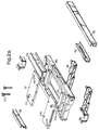
- the base frame (figure 2a) is constructed as a welded structure from sheet steel which has been folded to provide a generally rectangular cross sectioned tube and is braced by first and second transverse members 111a, 111b, and by a cross member 16 disposed between the transverse members. Further bracing or stiffening of the base frame is provided by base stiffener members 112, 113 attached to the front and rear respectively of the base frame and a longitudinal member 114 disposed between the transverse members. A kick plate 115 may also be attached to the front surface of the base frame. First and second anchor plates 17 formed from steel plate are disposed on the base frame whereby the rack may be secured to a support surface.
- the anchor plates are provided each with slotted openings 171 for receiving bolts 172 for engaging corresponding threaded mounts (not shown) provided in the support surface Foot bracket members 18 provide a mounting for the base frame structure 11 on the support surface. Further openings 174 are provided in each anchor plate 17 in register with corresponding openings 115 in the respective transverse member 111a, 111b for receiving screw threaded adjustment feet (not shown) which may be used for mounting the rack on an uneven surface. In some applications the anchor plates may be replaced by bar members which perform an equivalent function
- the rack top frame 14 (figure 2) is of similar construction to that of the base frame and comprises a generally rectangular structure which is braced by transverse members 141 and by front and rear stiffeners 142 and 143 respectively.
- first and second bracket members 144 secured to the top frame may be used to secure the top of the rack to an overhead support (not shown).
- the rack can support telecommunications equipment disposed on circuit boards or cards which can be secured to the rack in the normal manner.
- This equipment may form part of a conventional wired or optical communications system, or it may form part of a mobile or a fixed access cellular communications system.
- the rack assembly is in use secured to a substantially horizontal mounting surface via anchor bolts 172 which are located in the slotted openings 171 in the anchor plates 17 these openings being disposed inboard of the base frame periphery.
- the bolts engage corresponding threaded mounts (not shown) provided at appropriate positions in the mounting surface, the slotted openings providing a degree of leeway or tolerance in the positioning of the threaded mounts
- the anchor bolts 172 are fully tightened to secure the base frame structure 11 in abutment with the mounting surface and are then further tightened so as to prestress the base frame by providing a slight distortion thereof. As shown in figure 3, this provides a downward force against the base structure and a corresponding reaction force on the base structure from the support surface.
- FIGS. 4a and 4b show respectively longitudinal and transverse cross-sections of the base of the rack.
- the anchor bolts 172 are further tightened, the anchor plates 17 are strained and the inner portions of the base frame structure are compressed relative to the outer portions so that the upper surface of the base frame structure assumes a dished or concave configuration.
- the magnitude of the distortion is small and is within the elastic limit of the base material and of the anchor plates. Typically this distortion is less than 1mm. For explanatory purposes the distortion has been shown exaggerated in figures 4a and 4b.
- the distortion of the base resulting from the over tightening of the anchor bolts is illustrated schematically by the curves A-A and A'-A' in figures 4a and 4b respectively.
- the forces imparted to the base structure via the support surface cause the base structure to distort between its normal dished concave configuration and a concave configuration of smaller radius of curvature, i.e. a more dished configuration, so as to absorb some of the received vibrational energy.
- This distortion is illustrated schematically by the curves B-B and B'-B' in figures 4a and 4b respectively.
- a sample of the rack to be tested is mounted on a horizontal platform which is subjected to vibrations of various frequencies and the response of the rack to those applied vibrations is determined.
- the upper portion of the rack is loaded with a mass of 100 pounds to represent the maximum quantity of equipment which the rack will hold when in service.
- This test is detailed in the Bellcore NEBS document referred to above.. We have found that by providing an appropriate degree of prestress of the base structure, the minimum frequency to which the rack responds can be raised to at least 6 Hz and typically to about 9Hz, i.e. well above the frequencies at which significant damage can occur.
- the precise degree of over tightening of the anchor bolts to distort the anchor bars and base frame to provide the desired prestressing will depend on the base construction and the total area or footprint of the base member and can be determined by experiment by tightening the anchor bolts to various torque settings and subjecting the rack to the Bellcore earthquake simulation test. In this way an optimum torque setting can be determined for a particular rack construction, and this torque setting is then applied to all similar racks when these are installed.
Landscapes
- Engineering & Computer Science (AREA)
- Computer Networks & Wireless Communication (AREA)
- Business, Economics & Management (AREA)
- Emergency Management (AREA)
- Health & Medical Sciences (AREA)
- Toxicology (AREA)
- Microelectronics & Electronic Packaging (AREA)
- Casings For Electric Apparatus (AREA)
- Vibration Prevention Devices (AREA)
Claims (11)
- Gerätegestell zur Halterung von Kommunikationsgeräten, das einen allgemein rechtwinkligen Basisteil (11), erste und zweite langgestreckte Seitenteile (12, 13), die sich von gegenüberliegenden Seiten des Basisteils in einer Richtung senkrecht zur Ebene des Basisteils erstrecken, einen Oberteil (14), der die freien Enden der Seitenteile miteinander verbindet, und eine Einrichtung zur Befestigung des Basisteils (11) an einer Auflageoberfläche einschließt, wobei die Befestigungseinrichtung zur Verformung und Vorbelastung des Basisteils derart ausgebildet ist, daß eine Kraft von dem Basisteil auf die Seitenteile (12, 13) übertragen wird, wodurch das Schwingungsansprechverhalten des Gerätegestells auf einen Wert angehoben wird, bei dem durch Erdbeben hervorgerufene Schwingungen des Gerätegestells verhindert werden.
- Gerätegestell nach Anspruch 1, bei dem die Vorbelastung des Basisteils eine Kompressionskraft auf einen inneren Bereich des Basisteils ausübt, um diesen inneren Bereich gegenüber dem äußeren Bereich des Basisteils zu komprimieren.
- Gerätegestell nach Anspruch 2, bei dem der Basisteil eine allgemein rechtwinklige Rahmenstruktur mit einem Außenumfang umfaßt, der eine rechtwinklige Öffnung umgibt.
- Gerätegestell nach Anspruch 3, bei dem der Basisteil sich in Querrichtung erstreckende Versteifungsteile einschließt, die zwischen gegenüberliegenden Seiten des Rahmenumfanges über die Öffnung hinweg angeordnet sind.
- Gerätegestell nach Anspruch 1, bei dem die ersten und zweiten Seitenteile in einer Längsrichtung gefaltet sind, um jeweilige Kabelkanäle entlang dieser Seitenteile zu bilden.
- Gerätegestell nach Anspruch 5, bei dem die Seitenteile mit Versteifungsteilen (121, 122); (131, 132) versehen sind.
- Gerätegestell nach Anspruch 6, bei dem Kabelhalteeinrichtungen (124, 134) in den Kanälen vorgesehen sind.
- Gerätegestell nach Anspruch 3, bei dem die Befestigungseinrichtung erste und zweite Verankerungsträger oder -platten umfaßt, die in Querrichtung zum Basisteil angeordnet sind und Öffnungen im Innenbereich des Umfanges des Basisteils zur Aufnahme jeweiliger Schrauben aufweisen, die mit entsprechenden Gewindebefestigungen in der Befestigungsoberfläche in Eingriff stehen, wobei die Vorbelastung des Basisteils durch Ausüben eines Drehmomentes auf die Schrauben erreicht wird, das ausreicht, um den Basisteil gegen die Befestigungsoberfläche zu drücken und den Basisteil zu verformen und vorzubelasten.
- Erdbebenbeständige Struktur, die einen allgemein rechtwinkligen Basisrahmenteil (11), erste und zweite langgestreckte Seitenteile, die sich von gegenüberliegenden Seiten des Basisteils in einer Richtung senkrecht zur Ebene des Basisteils erstrecken, einen allgemein rechtwinkligen Oberteil (14), der die freien Enden der Seitenteile miteinander verbindet, und eine Einrichtung zur Befestigung des Basisteils an einer Tragoberfläche einschließt, wobei die Befestigungseinrichtung so ausgebildet ist, daß sie den Basisteil vorbelastet und verformt, um auf diese Weise eine Kraft von dem Basisteil auf die Seitenteile (12, 13) zu übertragen, wodurch das Schwingungsansprechverhalten der Struktur auf einen Wert angehoben wird, bei dem durch Erdbeben hervorgerufene Schwingungen der Struktur verhindert werden.
- Verfahren zur Befestigung eines Gerätegestells zur Halterung von Kommunikationsgeräten an einer Tragoberfläche, wobei das Gerätegestell einen allgemein rechtwinkligen Basisteil (11), erste und zweite Seitenteile (12, 13), die sich von gegenüberliegenden Seiten des Basisteils in einer Richtung senkrecht zur Ebene des Basisteils erstrecken, einen Oberteil (14), der die freien Enden der Seitenteile miteinander verbindet, und eine Einrichtung zur Befestigung des Basisteils an der Tragoberfläche einschließt, wobei das Verfahren die Vorbelastung des Basisteils über die Befestigungseinrichtung derart einschließt, daß eine Kraft von dem Basisteil auf die Seitenteile übertragen wird, wodurch das Schwinungsansprechverhalten des Gerätegestells auf einen Wert angehoben wird, bei dem durch Erdbeben induzierte Schwingungen des Gerätegestells verhindert werden.
- Verfahren nach Anspruch 10, bei dem die Befestigungseinrichtung eine Anzahl von Schrauben umfaßt, die mit entsprechenden Gewindebefestigungen in der Tragoberfläche in Eingriff stehen, wobei das Verfahren das Ausüben eines Drehmomentes auf die Schrauben einschließt, das ausreicht, um den Basisteil zu verformen und vorzubelasten.
Applications Claiming Priority (1)
| Application Number | Priority Date | Filing Date | Title |
|---|---|---|---|
| PCT/GB1996/001662 WO1998003048A1 (en) | 1996-07-12 | 1996-07-12 | Equipment rack |
Publications (2)
| Publication Number | Publication Date |
|---|---|
| EP0910937A1 EP0910937A1 (de) | 1999-04-28 |
| EP0910937B1 true EP0910937B1 (de) | 2000-09-20 |
Family
ID=10787666
Family Applications (1)
| Application Number | Title | Priority Date | Filing Date |
|---|---|---|---|
| EP96924058A Expired - Lifetime EP0910937B1 (de) | 1996-07-12 | 1996-07-12 | Baugruppenträger |
Country Status (6)
| Country | Link |
|---|---|
| US (1) | US5975315A (de) |
| EP (1) | EP0910937B1 (de) |
| JP (1) | JP3532218B2 (de) |
| DE (1) | DE69610441T2 (de) |
| NZ (1) | NZ331663A (de) |
| WO (1) | WO1998003048A1 (de) |
Families Citing this family (38)
| Publication number | Priority date | Publication date | Assignee | Title |
|---|---|---|---|---|
| GB9805585D0 (en) * | 1998-03-16 | 1998-05-13 | Willsher & Quick Ltd | Improvements in or relating to enclosures |
| US6561602B1 (en) * | 1998-06-23 | 2003-05-13 | Hendry Mechanical Works | Equipment mounting racks and cabinets |
| US6179133B1 (en) * | 1999-08-30 | 2001-01-30 | Newton Instrument Company, Inc. | Seismic rack with extension subassembly |
| US6349837B1 (en) * | 1999-11-10 | 2002-02-26 | Marconi Communications, Inc. | Stiffened relay rack |
| USD438177S1 (en) | 2000-01-20 | 2001-02-27 | Joseph W. Rogers | Cable management rack |
| US6338413B1 (en) * | 2000-06-02 | 2002-01-15 | Newton Instrument Company, Inc. | Mass customization telecommunications equipment rack |
| CA2313895A1 (en) * | 2000-07-12 | 2002-01-12 | Alcatel Networks Corporation | Mounting apparatus for equipment enclosures having cable bend radius control and channel for retaining cable |
| US6279756B1 (en) * | 2000-09-05 | 2001-08-28 | Newton Instrument Company, Inc. | Telecommunications equipment rack having improved structural strength |
| US6520345B1 (en) * | 2000-09-28 | 2003-02-18 | Hubbell Incorporated | Self-squaring relay rack assembly |
| US6519145B1 (en) | 2000-11-09 | 2003-02-11 | Axerra Networks, Ltd. | ETSI/NEBS housing structure |
| US6321917B1 (en) * | 2000-11-14 | 2001-11-27 | Adc Telecommunications, Inc. | Cable management rack for telecommunications equipment |
| CA2430136A1 (en) * | 2000-11-30 | 2002-06-06 | Kevin R. Henderson | Earthquake resistant equipment rack |
| DE10111314C1 (de) * | 2001-03-09 | 2002-07-25 | Rittal Gmbh & Co Kg | Traggestell |
| US6629614B2 (en) * | 2001-05-01 | 2003-10-07 | Nortel Networks Limited | Mounting for telecommunications equipment |
| US6889853B2 (en) * | 2001-12-20 | 2005-05-10 | Sanmina Enclosure Systems Division | Earthquake-resistant equipment rack |
| US20040069725A1 (en) * | 2002-07-10 | 2004-04-15 | Adducci Samuel J. | Seismically resistant network equipment rack |
| US6920273B2 (en) * | 2002-08-20 | 2005-07-19 | Adc Telecommunications, Inc. | High density fiber distribution frame |
| US7986124B2 (en) * | 2003-09-22 | 2011-07-26 | Valence Technology, Inc. | Electrical systems, battery assemblies, and battery assembly operational methods |
| US20060043031A1 (en) * | 2004-08-26 | 2006-03-02 | Cooper Technologies Company | Electronic equipment rack |
| US7874433B2 (en) * | 2005-04-28 | 2011-01-25 | Ortronics, Inc. | Seismically sound rack system |
| US20070175836A1 (en) * | 2006-01-27 | 2007-08-02 | Gerhard Bumeder | Frame structure |
| DE202006004211U1 (de) * | 2006-03-16 | 2006-05-11 | Knürr AG | Schrank |
| JP3947553B1 (ja) * | 2006-03-31 | 2007-07-25 | 株式会社日立コミュニケーションテクノロジー | 電子装置 |
| US9148980B2 (en) * | 2007-07-13 | 2015-09-29 | Dell Products L.P. | System for a rack design |
| US20090283488A1 (en) | 2008-05-19 | 2009-11-19 | Chatsworth Products, Inc. | Seismically hardened two-post electronic equipment rack |
| US8901438B2 (en) | 2010-09-10 | 2014-12-02 | Chatsworth Products, Inc. | Electronic equipment cabinet structure |
| US8787023B2 (en) | 2010-09-10 | 2014-07-22 | Chatsworth Products, Inc. | Rail mounting clamp for electronic equipment enclosure |
| EP2429272A2 (de) | 2010-09-10 | 2012-03-14 | Chatsworth Products, Inc. | Kabeldurchlaufpaneel für Gehäuse eines elektronischen Geräts |
| WO2015097779A1 (ja) * | 2013-12-25 | 2015-07-02 | 株式会社日立製作所 | ラック、ラックの異常検出装置及びその方法 |
| US10412854B1 (en) * | 2015-09-14 | 2019-09-10 | Google Llc | Restraining data center equipment |
| US10330299B1 (en) * | 2018-05-31 | 2019-06-25 | Mitek Corp., Inc. | Electronic rack crown |
| WO2022061129A1 (en) | 2020-09-17 | 2022-03-24 | Panduit Corp. | Optical distribution and splice frame including cassettes |
| US11818860B1 (en) | 2020-12-15 | 2023-11-14 | Chatsworth Products, Inc. | Frame structure for electronic equipment enclosure |
| US11678456B1 (en) | 2020-12-15 | 2023-06-13 | Chatsworth Products, Inc. | Slidable mounting hardware for electronic equipment enclosure and method for installing same |
| US11622458B1 (en) | 2020-12-15 | 2023-04-04 | Chatsworth Products, Inc. | Brush port assembly and method for installing same |
| US12048108B1 (en) | 2020-12-15 | 2024-07-23 | Chatsworth Products, Inc. | Caster attachment system using mating features |
| US11920392B1 (en) | 2021-02-02 | 2024-03-05 | Chatsworth Products, Inc. | Electrical bonding door hinges |
| GB2622384B (en) * | 2022-09-14 | 2025-05-28 | Bae Systems Plc | Ruggedisation apparatus |
Family Cites Families (8)
| Publication number | Priority date | Publication date | Assignee | Title |
|---|---|---|---|---|
| US4715502A (en) * | 1986-02-20 | 1987-12-29 | Newton Instrument Company | Telephone equipment rack |
| US5004107A (en) * | 1989-05-05 | 1991-04-02 | Hendry Mechanical Works | Earthquake braced racks |
| JP2693906B2 (ja) * | 1993-12-03 | 1997-12-24 | 日本電気エンジニアリング株式会社 | 通信装置取付枠 |
| DE19507728C1 (de) * | 1995-03-07 | 1996-08-22 | Loh Kg Rittal Werk | Schaltschrank mit Rahmengestell und Sockel |
| US5566836A (en) * | 1995-06-01 | 1996-10-22 | Homaco, Inc. | Telecommunication relay rack |
| US5788087A (en) * | 1996-03-18 | 1998-08-04 | Ortronics, Inc. | Hinged wire management panel assembly |
| US5819956A (en) * | 1997-02-25 | 1998-10-13 | Sigma-Aldrich Company | Rack for electrical equipment |
| US5867372A (en) * | 1997-04-16 | 1999-02-02 | Advanced Optronics Corp. | Frame structure for mounting telecommunications equipment |
-
1996
- 1996-07-12 EP EP96924058A patent/EP0910937B1/de not_active Expired - Lifetime
- 1996-07-12 DE DE69610441T patent/DE69610441T2/de not_active Expired - Fee Related
- 1996-07-12 JP JP50569998A patent/JP3532218B2/ja not_active Expired - Fee Related
- 1996-07-12 NZ NZ331663A patent/NZ331663A/xx unknown
- 1996-07-12 WO PCT/GB1996/001662 patent/WO1998003048A1/en not_active Ceased
- 1996-07-12 US US09/142,667 patent/US5975315A/en not_active Expired - Fee Related
Also Published As
| Publication number | Publication date |
|---|---|
| DE69610441T2 (de) | 2001-01-25 |
| NZ331663A (en) | 1999-03-29 |
| WO1998003048A1 (en) | 1998-01-22 |
| EP0910937A1 (de) | 1999-04-28 |
| DE69610441D1 (de) | 2000-10-26 |
| JP2000514603A (ja) | 2000-10-31 |
| US5975315A (en) | 1999-11-02 |
| JP3532218B2 (ja) | 2004-05-31 |
Similar Documents
| Publication | Publication Date | Title |
|---|---|---|
| US5975315A (en) | Equipment rack | |
| US5889648A (en) | Seismic cabinet | |
| US5533307A (en) | Seismic energy dissipation device | |
| US4884863A (en) | Optical fiber splicing enclosure for installation in pedestals | |
| US9526193B2 (en) | Information technology apparatus and associated transportable information technology hosting center | |
| US11904953B2 (en) | Modular saddle mount retained in a frame cross member for reducing vibration in heavy equipment cabs | |
| US5330066A (en) | Two tier frame | |
| US11718355B2 (en) | Modular saddle mount and modified frame cross member for reducing vibration in heavy equipment cabs | |
| US5979672A (en) | Earthquake resistant enclosure for electronic equipment | |
| EP3500077B1 (de) | Entwurf eines gestells für seismische stösse in der tiefe | |
| CA2216392A1 (en) | Improved electronic rack and mounting frame | |
| US20090085449A1 (en) | Extension apparatus for previously installed electrical cabinets | |
| US11840284B2 (en) | Modular saddle mount with isolator retained in a frame for reducing vibration in heavy equipment cabs | |
| CA2263627A1 (en) | Seismic subframe for electrical enclosure | |
| US11840279B2 (en) | Secondary retention devices for retaining a heavy equipment cab on a frame | |
| US20230132968A1 (en) | Isolator Adapter Insert For Retention In A Modular Saddle Mount Or An Isolator Mounting Plate For Reducing Vibration In Heavy Equipment Cabs | |
| KR101027917B1 (ko) | 내진 골조구조로 된 수배전반용 외함 | |
| US20240244352A1 (en) | Ballasted telecommunications equipment mounts and assemblies | |
| KR880000815B1 (ko) | 완충 마운팅 장치 | |
| KR102138606B1 (ko) | 좌굴방지 기능을 구비한 제진 장치 | |
| KR101742051B1 (ko) | 내진장치가 구비된 배전반 | |
| KR101240410B1 (ko) | 가변기능을 구비한 면진장치 | |
| US20030116513A1 (en) | Earthquake-resistant equipment rack | |
| KR102123397B1 (ko) | 수변전 설비용 내진마운트 | |
| CA2235657A1 (en) | Seismic resistant equipment rack |
Legal Events
| Date | Code | Title | Description |
|---|---|---|---|
| PUAI | Public reference made under article 153(3) epc to a published international application that has entered the european phase |
Free format text: ORIGINAL CODE: 0009012 |
|
| 17P | Request for examination filed |
Effective date: 19990212 |
|
| AK | Designated contracting states |
Kind code of ref document: A1 Designated state(s): DE FR GB GR IT |
|
| RAP3 | Party data changed (applicant data changed or rights of an application transferred) |
Owner name: NORTEL NETWORKS CORPORATION |
|
| GRAG | Despatch of communication of intention to grant |
Free format text: ORIGINAL CODE: EPIDOS AGRA |
|
| GRAG | Despatch of communication of intention to grant |
Free format text: ORIGINAL CODE: EPIDOS AGRA |
|
| GRAH | Despatch of communication of intention to grant a patent |
Free format text: ORIGINAL CODE: EPIDOS IGRA |
|
| 17Q | First examination report despatched |
Effective date: 20000113 |
|
| GRAH | Despatch of communication of intention to grant a patent |
Free format text: ORIGINAL CODE: EPIDOS IGRA |
|
| ITF | It: translation for a ep patent filed | ||
| GRAA | (expected) grant |
Free format text: ORIGINAL CODE: 0009210 |
|
| AK | Designated contracting states |
Kind code of ref document: B1 Designated state(s): DE FR GB GR IT |
|
| RAP2 | Party data changed (patent owner data changed or rights of a patent transferred) |
Owner name: NORTEL NETWORKS LIMITED |
|
| ET | Fr: translation filed | ||
| REF | Corresponds to: |
Ref document number: 69610441 Country of ref document: DE Date of ref document: 20001026 |
|
| PG25 | Lapsed in a contracting state [announced via postgrant information from national office to epo] |
Ref country code: GR Free format text: LAPSE BECAUSE OF FAILURE TO SUBMIT A TRANSLATION OF THE DESCRIPTION OR TO PAY THE FEE WITHIN THE PRESCRIBED TIME-LIMIT Effective date: 20001222 |
|
| PLBE | No opposition filed within time limit |
Free format text: ORIGINAL CODE: 0009261 |
|
| STAA | Information on the status of an ep patent application or granted ep patent |
Free format text: STATUS: NO OPPOSITION FILED WITHIN TIME LIMIT |
|
| 26N | No opposition filed | ||
| REG | Reference to a national code |
Ref country code: GB Ref legal event code: IF02 |
|
| PGFP | Annual fee paid to national office [announced via postgrant information from national office to epo] |
Ref country code: GB Payment date: 20030612 Year of fee payment: 8 |
|
| PGFP | Annual fee paid to national office [announced via postgrant information from national office to epo] |
Ref country code: FR Payment date: 20030702 Year of fee payment: 8 |
|
| PGFP | Annual fee paid to national office [announced via postgrant information from national office to epo] |
Ref country code: DE Payment date: 20030731 Year of fee payment: 8 |
|
| PG25 | Lapsed in a contracting state [announced via postgrant information from national office to epo] |
Ref country code: GB Free format text: LAPSE BECAUSE OF NON-PAYMENT OF DUE FEES Effective date: 20040712 |
|
| PG25 | Lapsed in a contracting state [announced via postgrant information from national office to epo] |
Ref country code: DE Free format text: LAPSE BECAUSE OF NON-PAYMENT OF DUE FEES Effective date: 20050201 |
|
| GBPC | Gb: european patent ceased through non-payment of renewal fee |
Effective date: 20040712 |
|
| PG25 | Lapsed in a contracting state [announced via postgrant information from national office to epo] |
Ref country code: FR Free format text: LAPSE BECAUSE OF NON-PAYMENT OF DUE FEES Effective date: 20050331 |
|
| REG | Reference to a national code |
Ref country code: FR Ref legal event code: ST |
|
| PG25 | Lapsed in a contracting state [announced via postgrant information from national office to epo] |
Ref country code: IT Free format text: LAPSE BECAUSE OF NON-PAYMENT OF DUE FEES;WARNING: LAPSES OF ITALIAN PATENTS WITH EFFECTIVE DATE BEFORE 2007 MAY HAVE OCCURRED AT ANY TIME BEFORE 2007. THE CORRECT EFFECTIVE DATE MAY BE DIFFERENT FROM THE ONE RECORDED. Effective date: 20050712 |